Project 1 : CFD Meshing for Tesla Cyber Truck
AIM : To perform a Meshing for a Tesla cyber Truck model and to check the Quality element criteria for a car model.
PROCEDURE :
- open the model.
- since many surfaces are in red cons so use topo then reduce the red cons.
- since double cons are not present in middle part of model, use plane cut option and delete the half model because car is symmetry model.
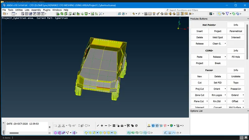
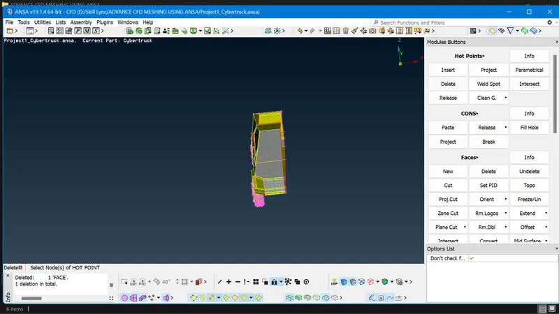
- Check the geometry errors, since some faces are missing so use new option in face group fill the surfaces.
- To to cons solution use length option in Mesh group and give 1mm in both perimeters and Macros.
- Since both half sides are symmetry, only one half side can be correct and do symmetry other side.
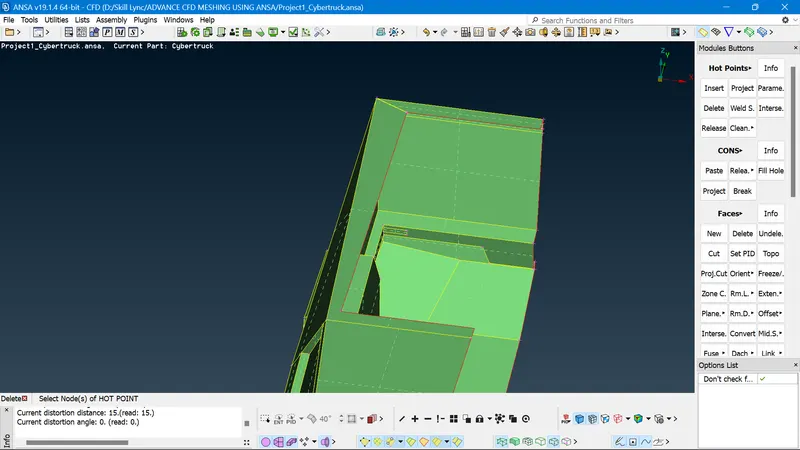
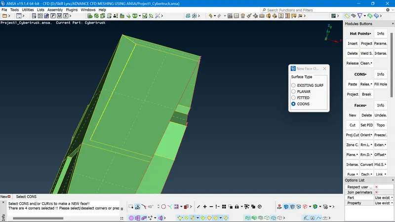
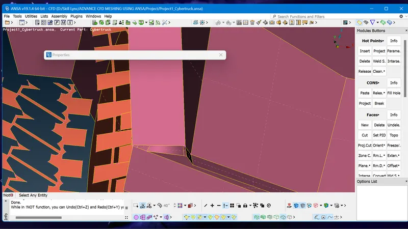
1. LIGHTS
- Delete the inner side surface part.
- Below the light part there is intersection surfaces.
- Delete the surface by using cut option and delete option.
- Fill the surface by new option.
2. TYRES
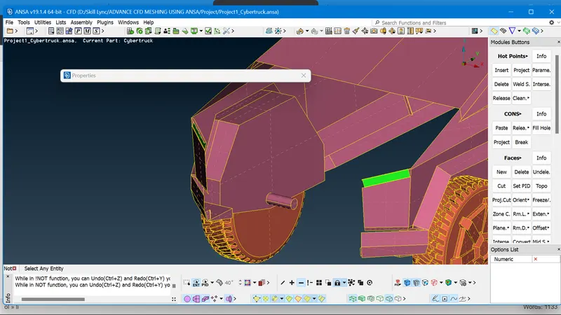
- First clear all single cons.
- Select each tyre make isolate then clear all single cons and intersection surfaces or overlapped surfaces.
- By using fill hole option fill the hole.
- Delete the all intersection error.
- Again check the geometry checks and clear the error.
- Do same thing to other tyre part.
ASSIGN PID'S
- Assign PIS's for Lights, Tyres and Body.
- use open foam in decks by click the box edit criteria visibility select the unrequired criteria and remove it from the list.
- select mesh parameter save the quality criteria, in some regions the length of the surfaces are less then target length so to avoid fail, make cut in regions and remove line by rtight click of cut option.
- The target length of PID'S are
- Light = 2mm
- Tyres = 3mm
- Body = 4mm
- For light Isolate logo check quality criteria
- For light minimum length 1mm and maximum is 3mm.
- Give the values in both quality criteria andf in mesh parameter, give perimeter and macros in perimeter group and select a spot mesh option in mesh generations.
- Then select hidden mode and PID region to see the how mesh are done, to clear the OFF elements.
- For Tyres target length is 3mm minimum and maximum are 2and 4, clear OFF elements.
- For body give target lengthy as 4mm and minimum and maximum are 3mm and 5mm.
- Click on the OFF element, click on Improve and clear all OFF element.
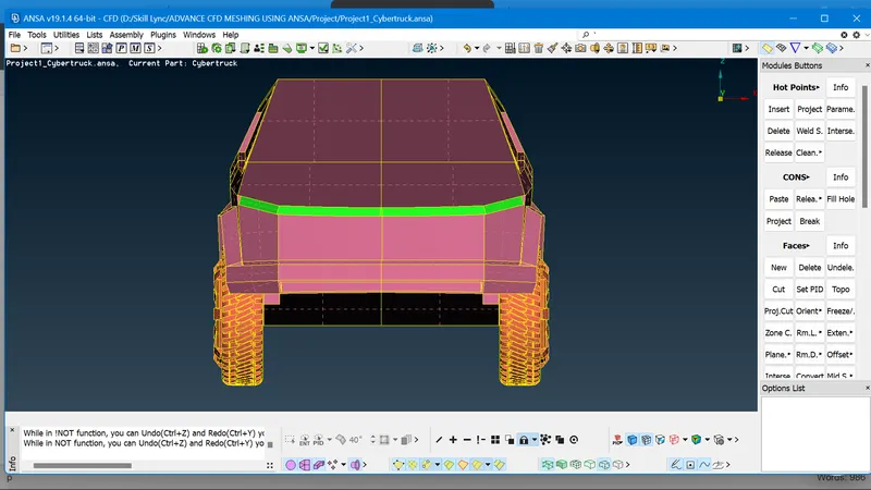
SYMMETRY
- Make top view of the model select tranform option click on copy option then entities select whole model, deselect the logo part then middle click on symmetry.
- Click on mirror 3 points plane in use group, select 3 points in the model then middle click check preview themn Finally finish.
- In some region single cons are presented so by using paste option clear cons error, select paste option in coons group in topo mode, mesh the again.
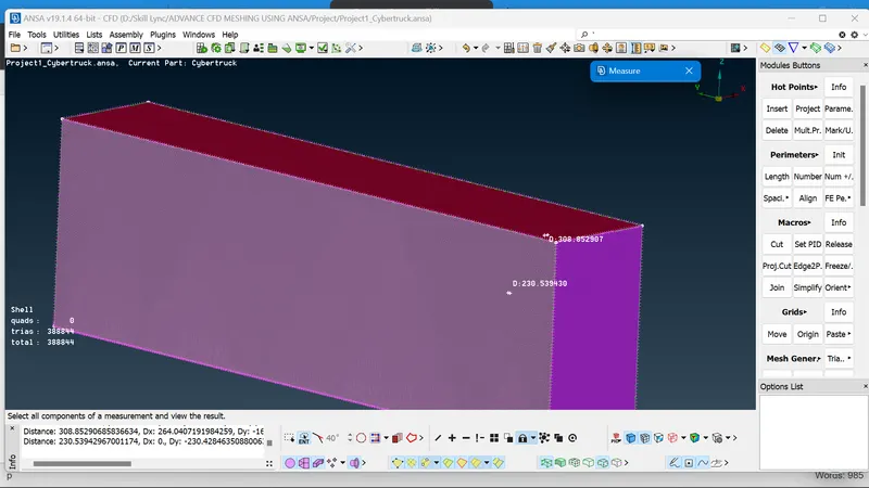
WIND TUNNEL: Wind tunnel is medium where car is placed and blow a wind, so that nature of flow in car can be determine and do CFD analysis.
- To make wind tunnel first need to make a path.
- So that take a total car body length from front and rear side, so consider 'X' term
- X value is 5900mm.
- The front face of wind tunnel should be 4X distance so make reference point below the car surface use relative option in points group, and give length as dy as -1000.
- The front side surface length is from refence point to starting of car ie 2700mm.
- Click relative option and give values in dz as 4*5900+2700=26300 to front side.
- Same as rear siode from reference point to rear of car the length is 3300mm.
- For rear side click dz as -1 and 6*5900+3300=38700mm.
- Similarly Top side So don't take old reference point .
- Create new point in upper surface of car so use relative option in upper surface as 3*5900=17700.
- The sides surface should be length is Xmm, from centre point of front side to both right and left sides.
- It has to be dx as +1 and -1 and value is 5900mm.
- create curve using points.
- Create 5 new PID'S name as Top surface tunnel, Bottom surface tunnel, Front side tunnel, Rear side tunnel and Sides surface tunnel.
- Once Botton surface is created top surface to be create by offset option.
- The distance is 1530 to top tunnel height is 3X + 1530 = 19230mm.
- After surface created delete curves of points in bottom surface.
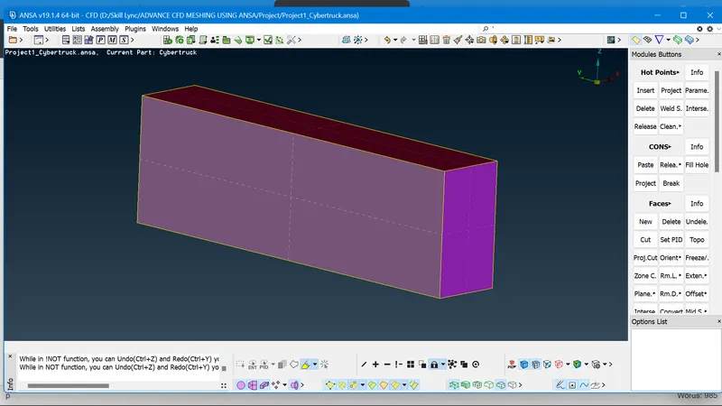
- Finally close all the sides using new option.
- The area of interest in bottom surface is 100mm and Top surface is 300 to this side surface of front and rear side will varies so use spacing option in perimeter group and change Linear to Geometric, Facto of safety is 1.1, dmin is 100 and dmax is 300.
- Click on con in bottom side so that arrow in upper direction facing, there is no need to give values in meshing quality because length of cons values is varies.
LEARNING OUTCOMES :
- In this project I learnt different new concepts.
- How a whole car have been meshed in step by step.
- The differnt concepts of procedures learnt and it is to length process.
RESULT :
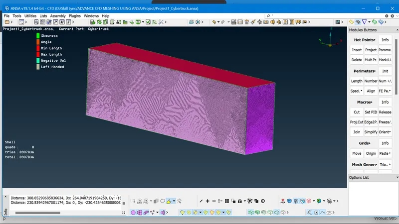
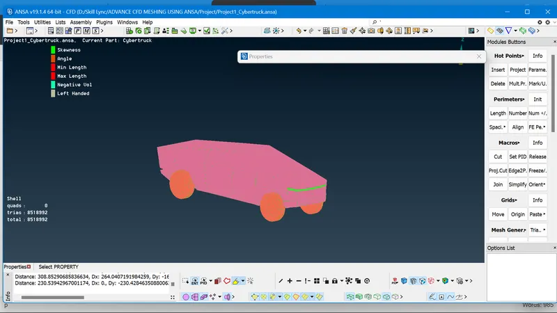
The surface model of the car meshed in given target length and different kinds of error are determined and cleared, The result is calculated and both car and winf tunnel is meshed and OFF elements of the whole model is Zero.
The image is attached below.
CONCLUSION:
- The whole car model details of knowledge is learnt step by step.
- The Problem solving and identifying the errors are noted.
- Different type of problrm in different procedure had identified, thge process takes time but during this task I have learnt new skills, I enjoyed the process, process of meshing solving the errors and finishing the task.
- Overall the meshing of both car model and wind tunnel surface is prepared.
The model is uploaded in Google drive, link is : https://drive.google.com/drive/folders/1QZUFnoYkjnN4jxvM4UtC6SwgHgDri5Yk?usp=sharing
THANK YOU