Project 1 : CFD Meshing for Tesla Cyber Truck
REPORT
AIM
CFD Meshing for Tesla Cyber Truck
OBJECTIVE
- To identify and clean up all the topological errors in the Tesla Cyber Truck Car model.
- To create a surface mesh.
- To create a wind tunnel surrounding the car.
- To generate a volumetric mesh to perform an external flow CFD analysis simulation.
MODEL
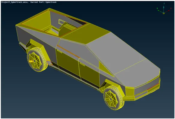
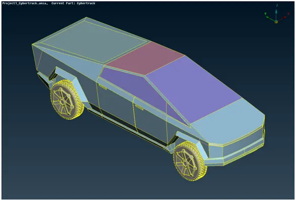
Tesla Cyber Truck
PROCEDURE
Geometry Clean Up
Select the mode of view as per view. Check wireframe mode to recognize the errors more clearly.
Identifying and clean up procedure
- To improve the cons resolutions of components move to the mesh deck and can provide the basic length to the nodes.
- The geometry can be seen with many faces missing, also very small dimensions of the faces can be a hindrance during surface meshing.
- Also, only double cons are required in the geometry. Triple cons should be avoided until unavoidable as it may lead to forming a local volume.
- Aim: To create a single volume inside the car with the volume of individual tires considered separately.
- Patch the open surfaces using coons/ fitted/ fill hole option to create a new surface accordingly.
- Before deleting any surface use cons2curve to register footprints of necessary cons.
Check Manager
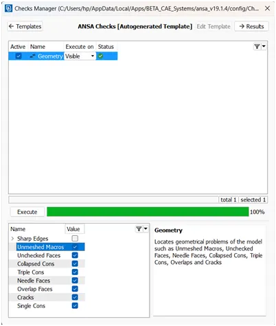
- After cleaning up all the topological errors, the geometry is checked using geometry checks under the checks manager.
- If no errors are shown then we can conclude that the model is ready for mesh.
PID Manager
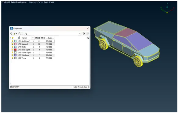
Assign the PID for different parts and provide a name and colour to differentiate between the components and ease up the working on the components individually. Also, delete empty PIDs which have no components assigned by using compress.
Surface Mesh
Here we perform all three tasks, defining the element size or length and setting the mesh parameters, selecting of meshing type and generating the surface mesh of the CAD model and resolving the errors in the surface mesh by selecting each PID one by one and performing the above tasks.
Mesh parameter, quality criteria, and length of both perimeter and macros values can be provided according to the table for different PIDs.
|
Parameter( mm ) |
Body |
Front Lights |
Rear Lights |
Tires |
Bed Roof |
Windows |
Sun Roof |
|
Target Length |
2.5 |
3 |
3 |
3 |
2 |
2 |
2 |
|
Minimum Length |
1 |
2 |
2 |
1 |
1 |
1 |
1 |
|
Maximum Length |
4 |
4 |
4 |
5 |
3 |
3 |
3 |
Different quality criteria for different surfaces will be used. The mesh length should be changed per the surface complexity and size. If the surface is small, the smallest target length should be considered. The element length should be set according to the distance of the surfaces as a fine mesh for every element would be time-consuming and will be computationally expensive.
As we start meshing considering one PID at a time, it is made sure that the Off Elements shown in hidden mode are resolved. This can be done using various options available in the module. Also, this can be reduced in TOPO mode where using cut tool surfaces smaller than the target length can be replaced with a bigger option.
The MOVE option in the module under Grids can be used to move nodes to maintain skewness.
Note
- If the mesh generated shows Off elements even after Reconstruction, there are chances that the TOPO cleanup of the PID is undone. So we can rectify the area showing errors anytime moving from the Mesh module to the TOPO module.
- It is recommended to start meshing from the smallest PID.
- Do not provide Macros to the body PID, also while providing Perimeters length to the body PID unselect the CONs which are attached to other PIDs. Ignoring this will erase the meshing of components at that location.0
- If the Perimeter length is not provided then the model gets meshed with 1mm as the element length by default.
Process
- We isolate each PID and give the above quality criteria ( skewness, min and max lengths, and the value for angles). Skewness – 0.7.
- Spot Mesh generation option is used to generate a mesh in each component.
- Then using reconstruct option under the shell mesh module the Off elements can be reduced or even eliminated.
- Do perform geometry checks for unmeshed, single cons and some other parameters for the full model to confirm no errors before moving on to create a wind tunnel.
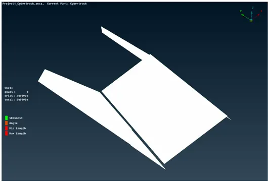
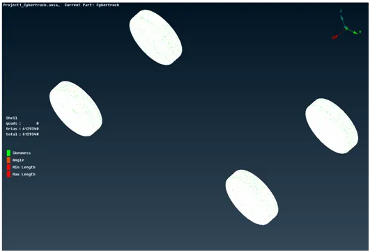
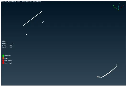
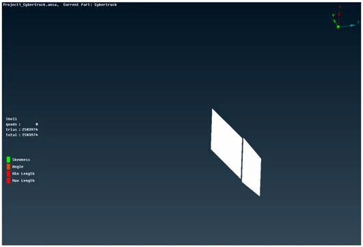
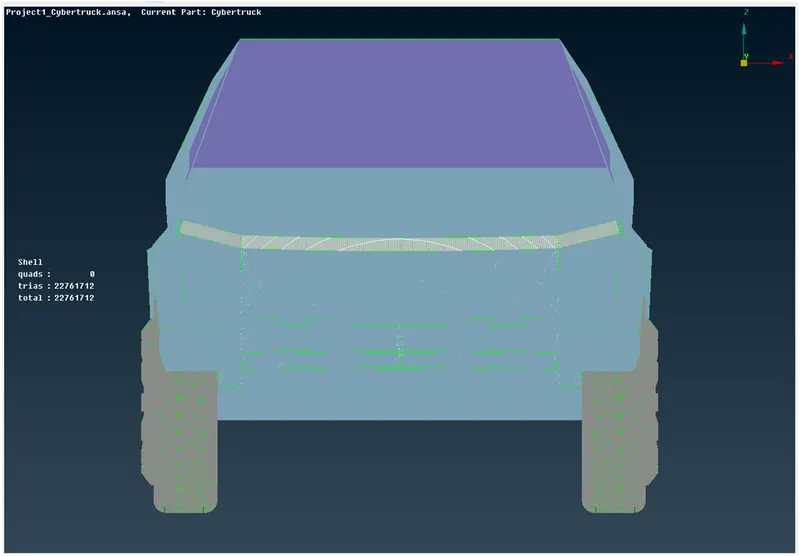
Final Individual PIDs with no OFF elements
Windows
Tires
Rear and Front Lights
Bed and Sun Roof
Final
Wind Tunnel
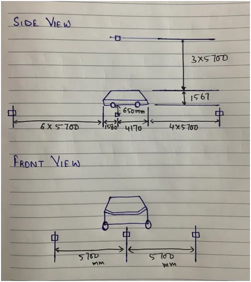
A wind tunnel is used for external CFD analysis and has to be designed in ANSA. It is created in TOPO mode as a Rectangular box.
Dimensions:
|
S.No. |
Surface |
Length |
|
1 |
Front |
4 * characteristic length of the truck |
|
2 |
Bottom |
Nearest to the wheels |
|
3 |
Back |
6 * characteristic length of the truck |
|
4 |
Top |
3 * characteristic length of the truck |
|
5 |
Sides |
characteristic length of the truck |
For this BMW car, the characteristic length was measured to be 5700 mm.
Tools
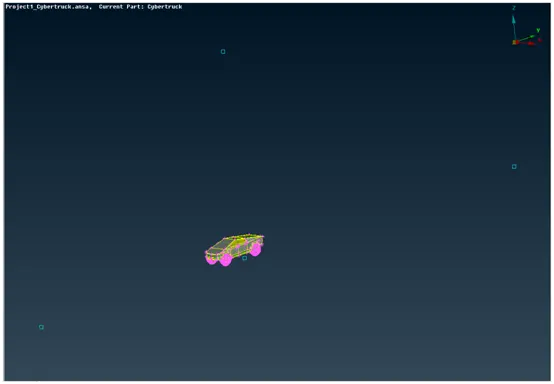
- Multiple vertices of the wind tunnel were created using TOPO --> Points --> Relative.
- These points were joined to form a linear curve using TOPO -->Curves --> Create.
- The curves were then used to create surfaces using TOPO --> Faces --> New
The curves and points were then removed. PIDs can be created for all the surfaces of the wind tunnel.
Nodes Created
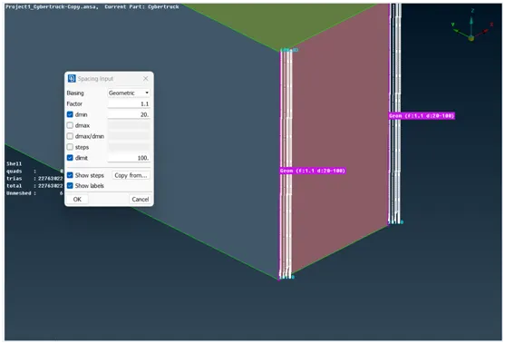
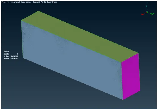
The meshing of Wind Tunnel Parameters
- The bottom side of the tunnel mesh length is 20 mm with min and max lengths as 15mm and 25mm respectively.
- The top side mesh length is 100 mm with min and max lengths of 80mm and 120mm respectively.
- Front and Back side mesh length
Perimeters --> Spacing
- Biasing – Geometric
- Factor – 1.1
- dmin – 20 mm
- dmax – 100 mm
Final Tunnel Meshing
VOLUMETRIC MESH
ANSA auto-detects 6 volumes. The only required volume is between the truck surface and the wind tunnel.
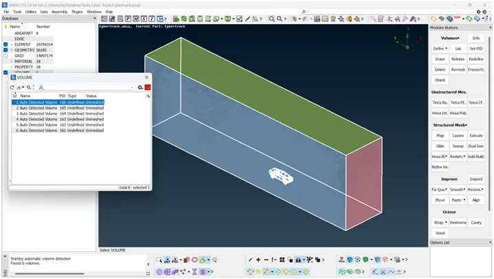
The other five volumes detected are four volumes of each tire individually, and the other one volume is for the car interior. These volumes can be deleted as they are not required for the external flow analysis.
Meshing
The required volume between the wind tunnel and truck model can be meshed using Tetra CFD under the unstructured mesh. The volume created will be hollow inside in the shape of the truck exterior.
LEARNING OUTCOMES
- Identification and cleanup of the topological errors.
- Geometry checkup and setting up of relevant PIDs and defining the element size.
- Setting the mesh parameters and quality criteria tool
- Resolving errors such as skewness, min and max lengths
- Creation of wind tunnel
CONCLUSION
- The imported CAD model of the Tesla cyber truck is topologically cleaned and corrected all the feasible surface errors to perform external aerodynamic analysis.
- The surface mesh is generated with the required element size.
- Reconstructed the mesh as per the mesh quality at corners and the intersection of edges.
- Worked with the errors that occurred in the mesh.
- Created a wind tunnel for external aerodynamic analysis.