Project 1 : CFD Meshing for Tesla Cyber Truck
Aim:
The aim is to create close volume of Cybertruck to perform external aerodynamics simulations.
Objective:
For the given model, check and solve all geometrical errors and Assign appropriate PIDs. Perform meshing with the suitable Target length and element Quality criteria.
Target lengths for the different parts of a model can be decided by your own. Finer mesh will give good results and will compromise with the longer processing time.
Answer:
Following target lengths for the different parts of a model are considered as follow:
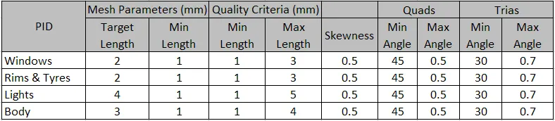
- Body - 3 mm
- Lights - 4 mm
- Rims and Tyres - 2 mm
- Window - 2 mm
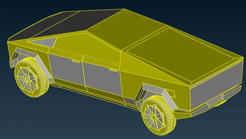
The model of cybertruck has been received in following condition:
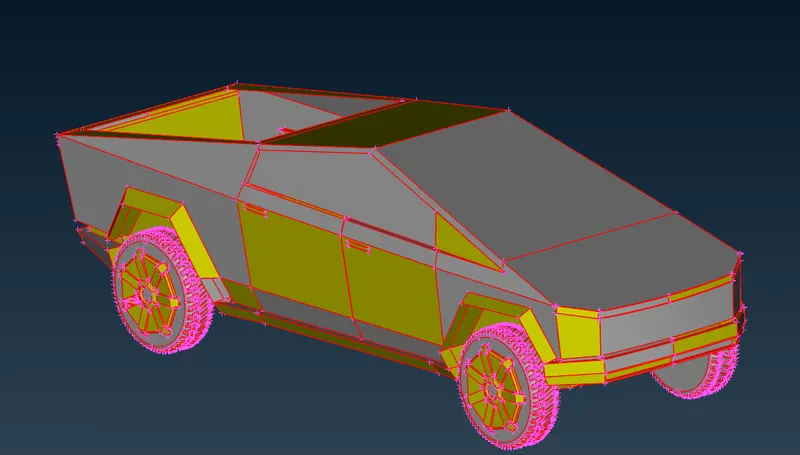
The topo command was applied on the whole model & model with following errors remained.
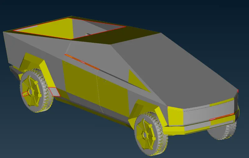
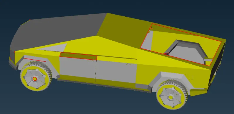
As it can be seen in the above images, surfaces were found missing highlighted with single CONS. These gaps were filled by creating new surfaces at those places.
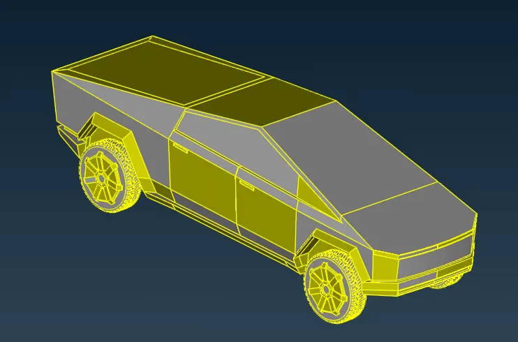
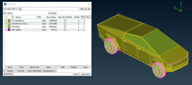
The PIDs have been assigned to the components.
Meshing:
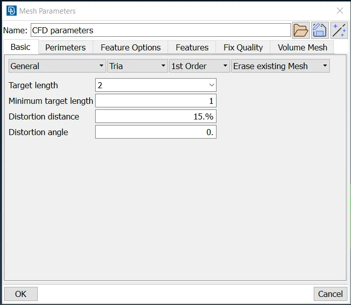
Before proceedings to mesh the components, Mesh parameters & quality criteria need to be assigned to each component. Following steps performed to mesh the Rims & Tyres PID are same for all components.
Rims & Tyres:
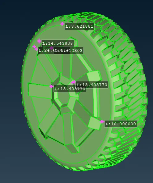
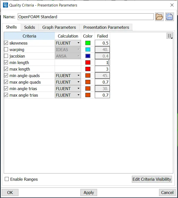
Small surfaces & edges were measured for their lengths before entering minimum & maximum length for the mesh elements in the quality criteria dialogue box.
Mesh Parameters
Quality Criterias:
Using "Length" command, the element sizes have been given to perimeters & to the macros (surfaces) equal to the element size enetered in Mesh parameters dialogue box.
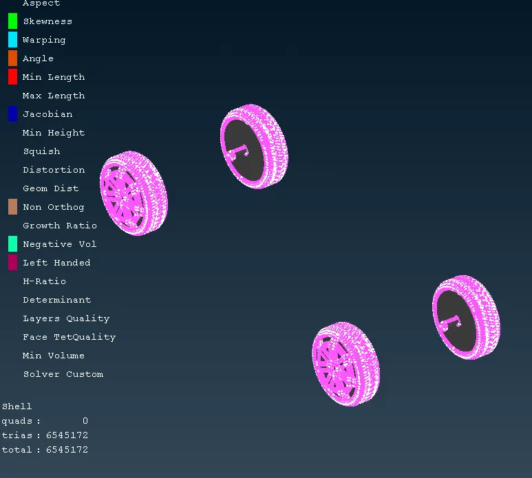
For tyres, one set of tyres have been deleted to save time for meshing. After generating mesh, offset elements errors have been resolved using commands from the below toolbars.
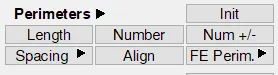
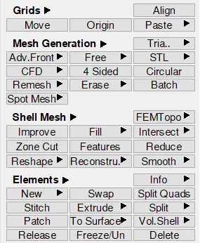
The generated mesh is shown below:
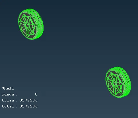
After performing symmetry, the 4 set tyres with meshing as been shown below:
For all other PIDs, the same procedure has been followed. The details of Mesh parameters & quality criteria have been tabulated in below table.
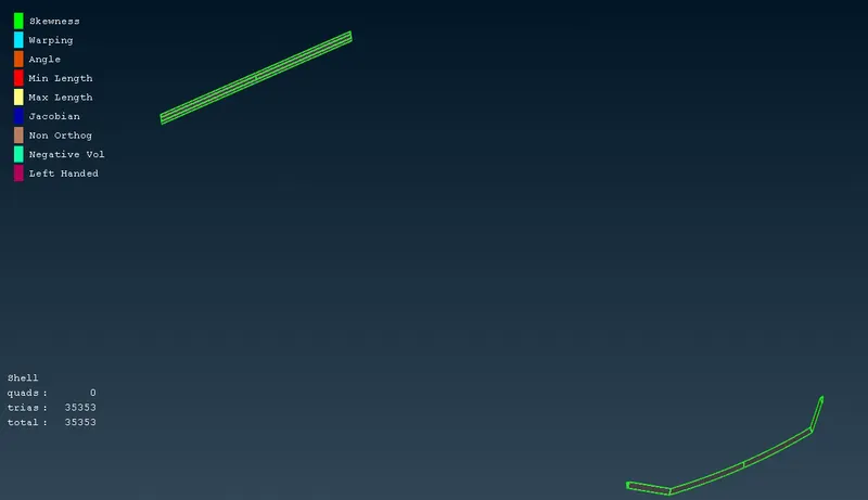
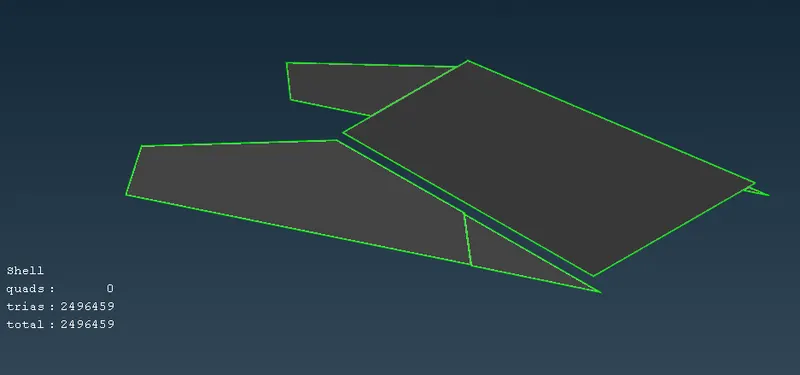
And the meshed components are shown in the below images:
Lights:
Windows:
Body:
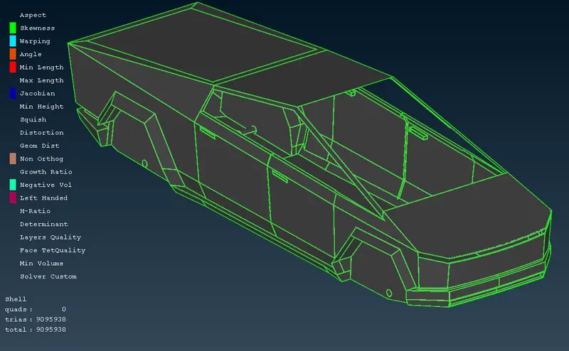
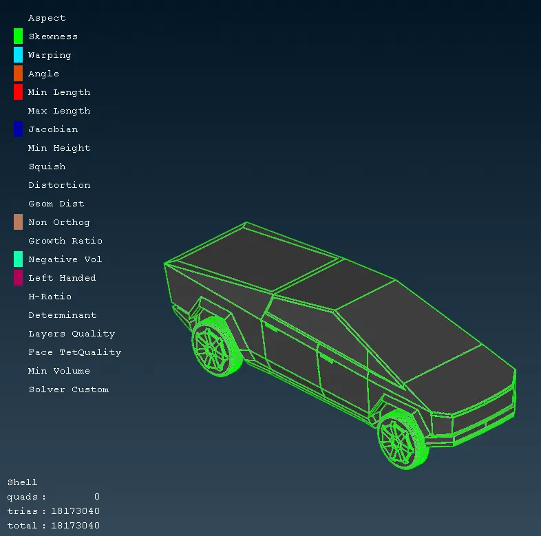
Final Model:
Wind Tunnel:
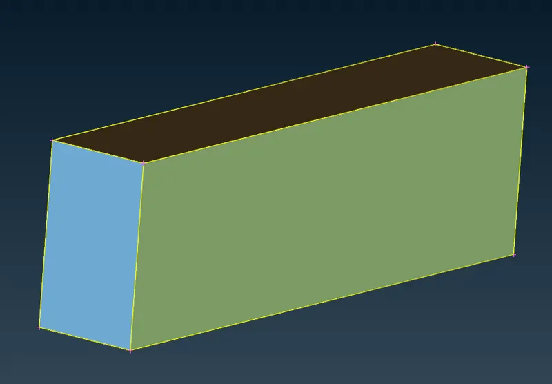
To create wind tunnel, the reference points has been created using "Realtive" tool available in Point toolbar. The faces of the wind tunnel have been created using "New" surface creation option.
Size of the wind tunnel
Car elngth (x) = 5880mm
Top = 3x + Distance from referecen point = 19740mm
Bottom = Just below the wheel
Front = 4x = 23520mm
Back = 6x + Distance from referecen point = 41160mm
Side = 1x = 5880mm
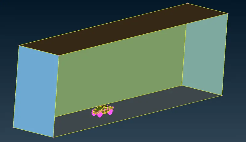
To perform mesh, the top face has been assigned the mesh element size of 100mm using "Length" tool to its perimeter & macros.
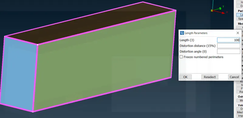
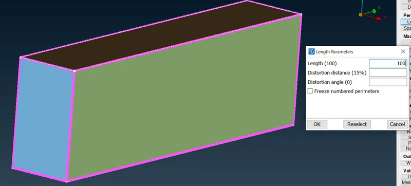
In similar way, the element size of 20mm has been assigned to bottom face.
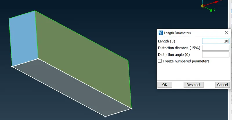
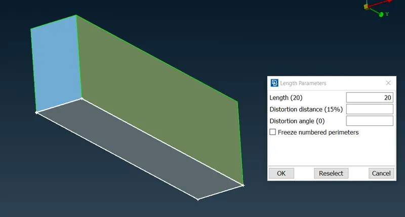
To accommodate different mesh sizes between top & bottom face, using "Spacing" tool the variable mesh sizes has been given which starts from 20mm and end with 100 mm mesh size with growth rate of 1.2.
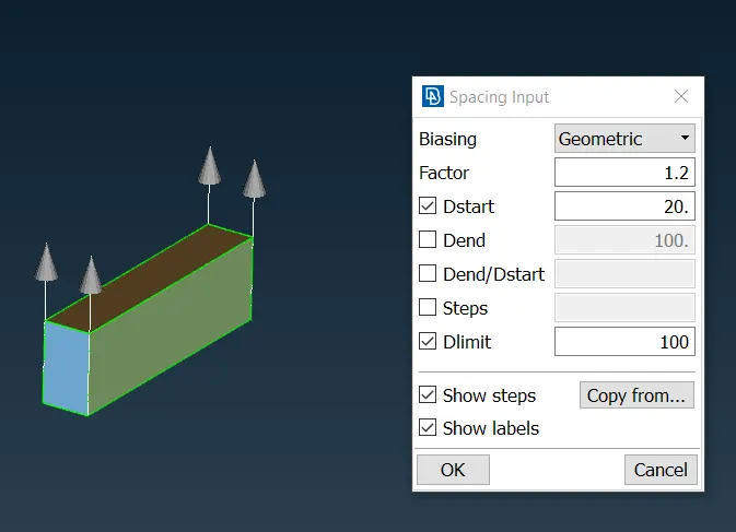
Due to limitation of computational power, the meshing of the wind tunnel was unsuccessful.
The attachment of model with the challenge was unsuccessful as well, thats why sharing you using google drive.