Project 1_Analyze and design a steel building to 10T CRANE as per IS standard code using TEKLA STRUCTURAL DESIGNER.
PROJECT 1 : Analyze and Design a steel building to 10T crane as per IS standard code in TEKLA STRUCTURAL DESIGNER.
Aim:
Using TEKLA STRUCTURAL DESIGNER, analyze and design a steel building to 10T CRANE in accordance with IS standard code. See the plan and elevation that are attached. For lateral stability, provide bracings and moment connections.
Think about wind loading, equipment, dead, and live. Take into account the 150 mm thick brick wall loads and 1.5 KN per square meter for the wall and roof cladding.
Assume 39 m/s as the baseline wind loading speed.
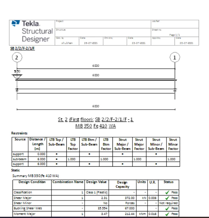
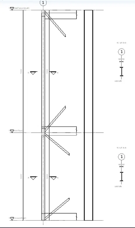
Each member's report is to be produced, and structural plan drawings are to be extracted from the software.
To create a steel structure with all the components and loads, analyze and design it using Tekla tools, and then verify its stability.
Procedure:
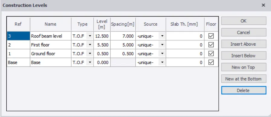
Building Levels for the specified model.
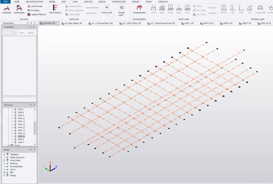
Make the grids on both sides in accordance with the provided layout.
constructing the model's member properties.
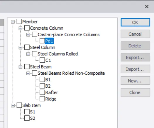
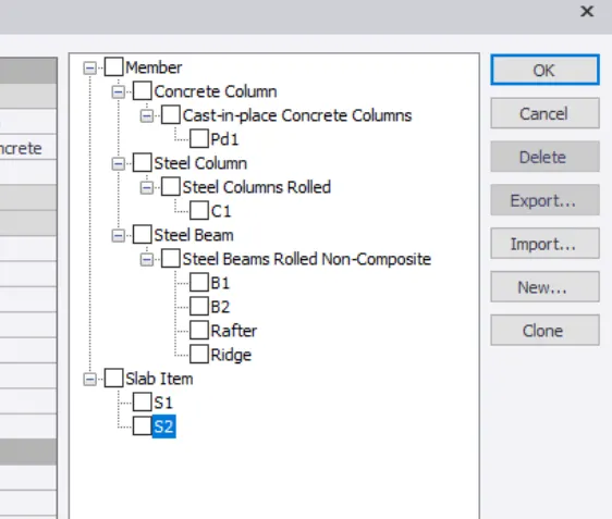
Section C1
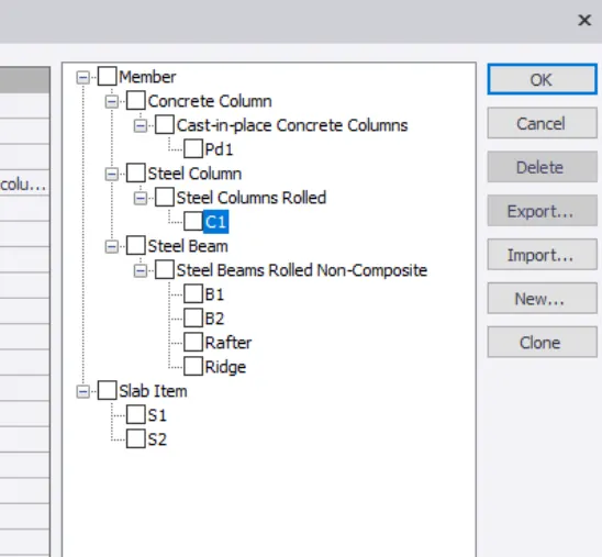
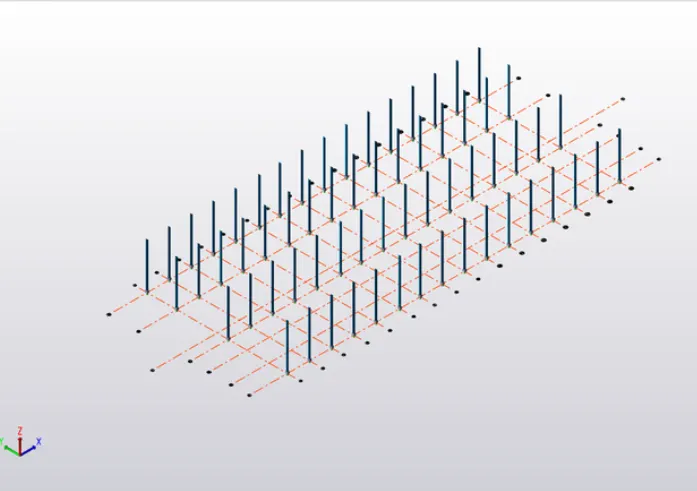
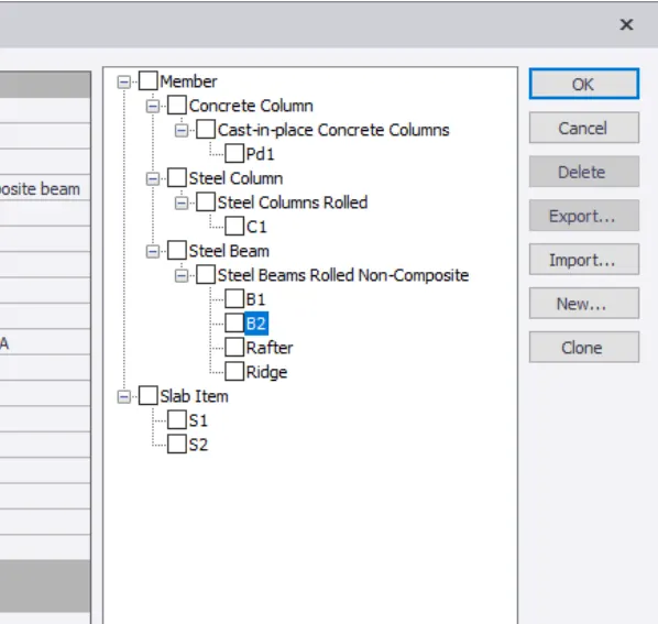
Beams B1 and B2
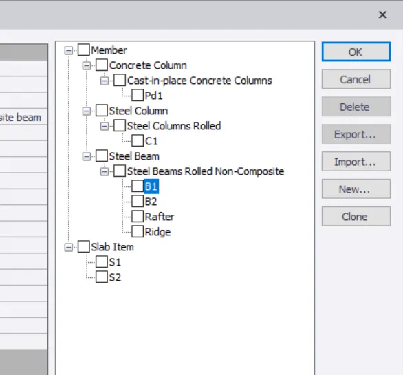
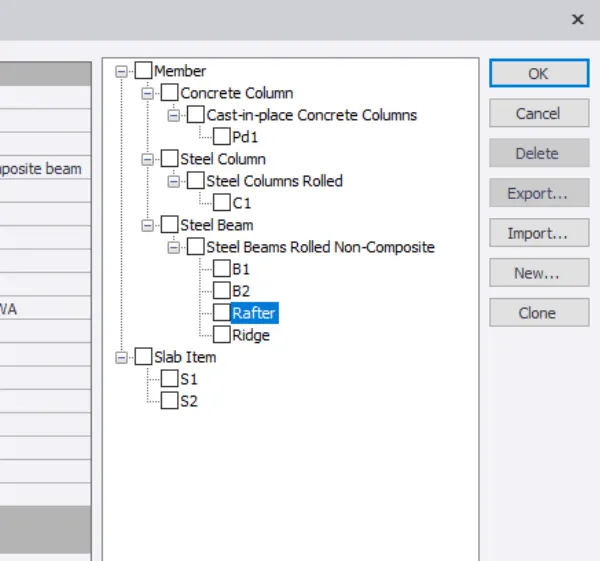
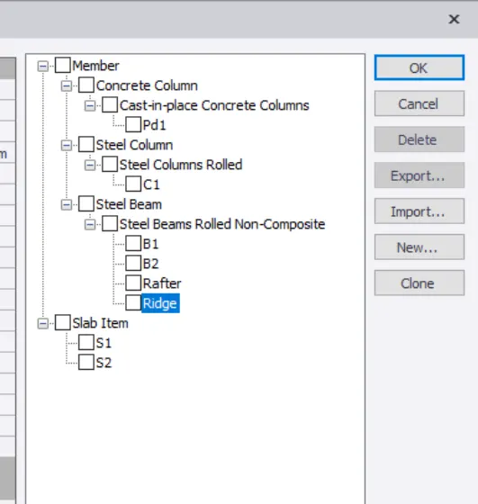
Properties of Ridge Slabs and Rafters:
S1: Two-way and S2 One-Way
Walls and panels are applied along with the bracings after the member properties have been assigned.
Wall panels on Frames A and F with bracings
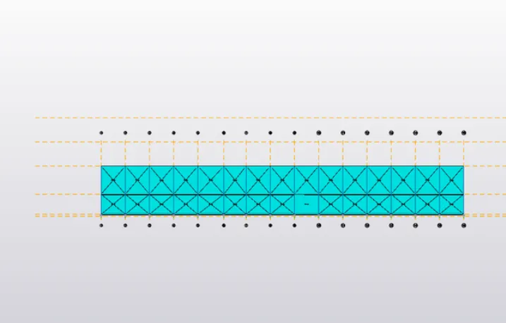
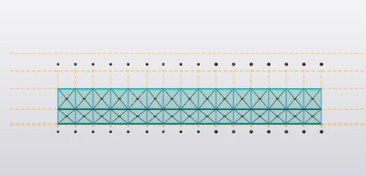
Wall panels with Frame 1 and 16 bracings
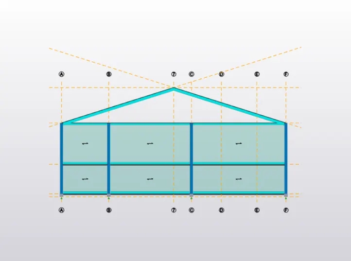
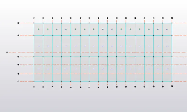
Ground floor
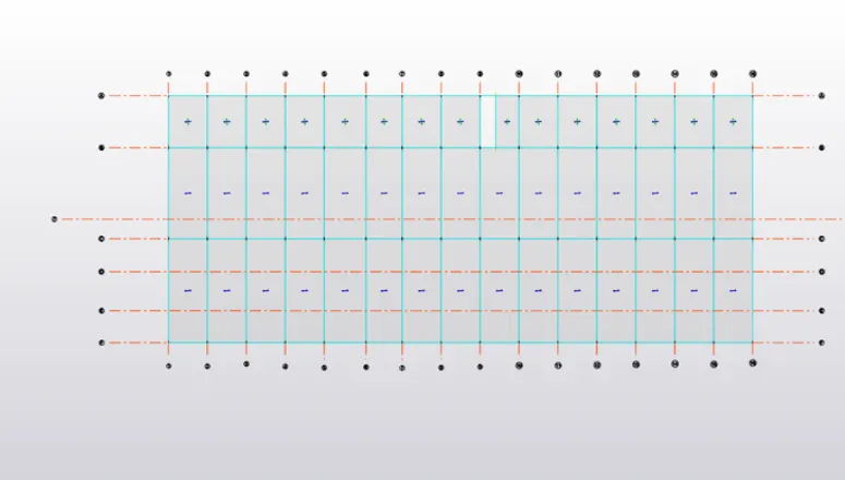
First Floor
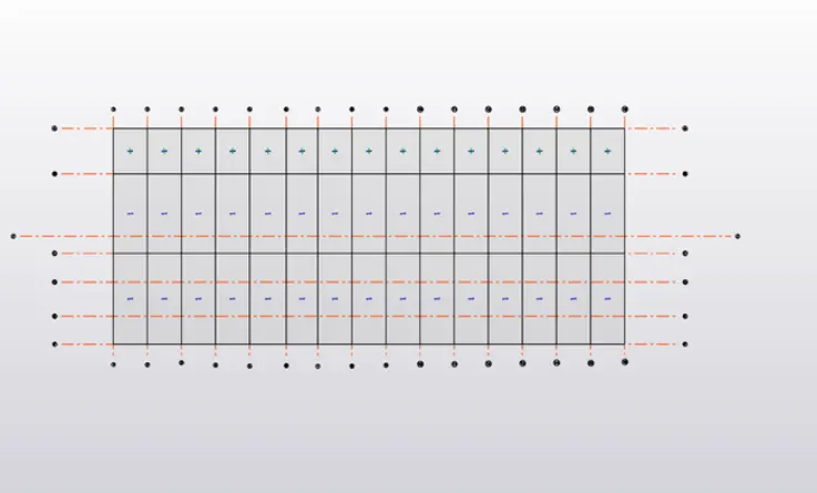
Roof Beam Level
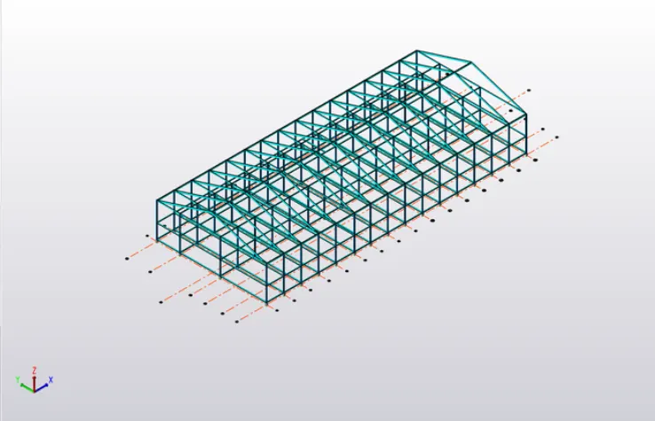
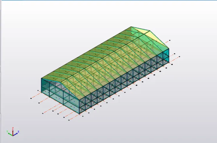
3D View
Load Calculations:
Concrete's unit weight is 24 KN/m^3.
1. Dead Load:
- Area loading (finish loading = 0.05x24 = 1.2 KN/m^2)
- Software will design the slab load.
- Brickwall activation
- Brickwall thickness: 150 mm
- Weight unit: 20 KN/m^3
- Floor height = 5 m from the ground to the first story
- Brickwall loads equal 0.15 x 20 x 7 = 21 KN/m.
- Roof loads calculated using 1.5 KN/m^2 purlin size.
- An upper limit of 0.3 KN/m^2
Combinations of loads are produced.
There is a 1.2 KN/m^2 dead load applied to the roof, first floor, and ground floor.
2. Live load:
- Ground Floor: 3 KN/m^
- for the office5 KN/m^2
- Staircase5 KN/m^2
- WorkshopTwo conference rooms = 5 KN/m^3 KN/m^2
- Pantry0.75 KN/m^2 for a flat roof without access2
- Yards of Maintenance = 2.5 KN/m^2
- Upkeep Room = 3 KN/m^2
3. Rooms on the First Floor:
- The Conference Room = 5 KN/m^2
- the Staircase = 5 KN/m^2.
- Kitchen = 2 KN/m^2
- Pantry = 3 KN/m^2
- Office = 3 KN/m^2
4. Roof:
Apply a 1.5 KN/m^2 area loading as the roof load for the 18 degree pitch roof.
5. wind Load calculating and applying
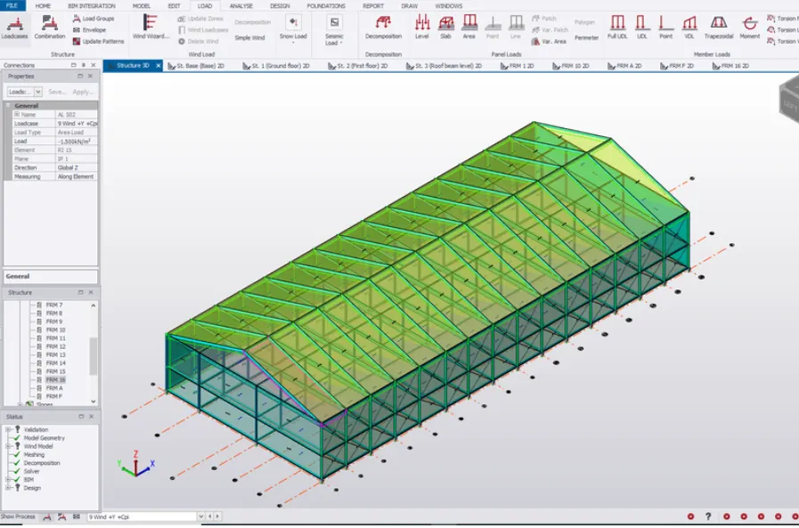
the 3D view is as shiown below
6. Crane load calculatins:
Crane Load Estimate:
Considering that
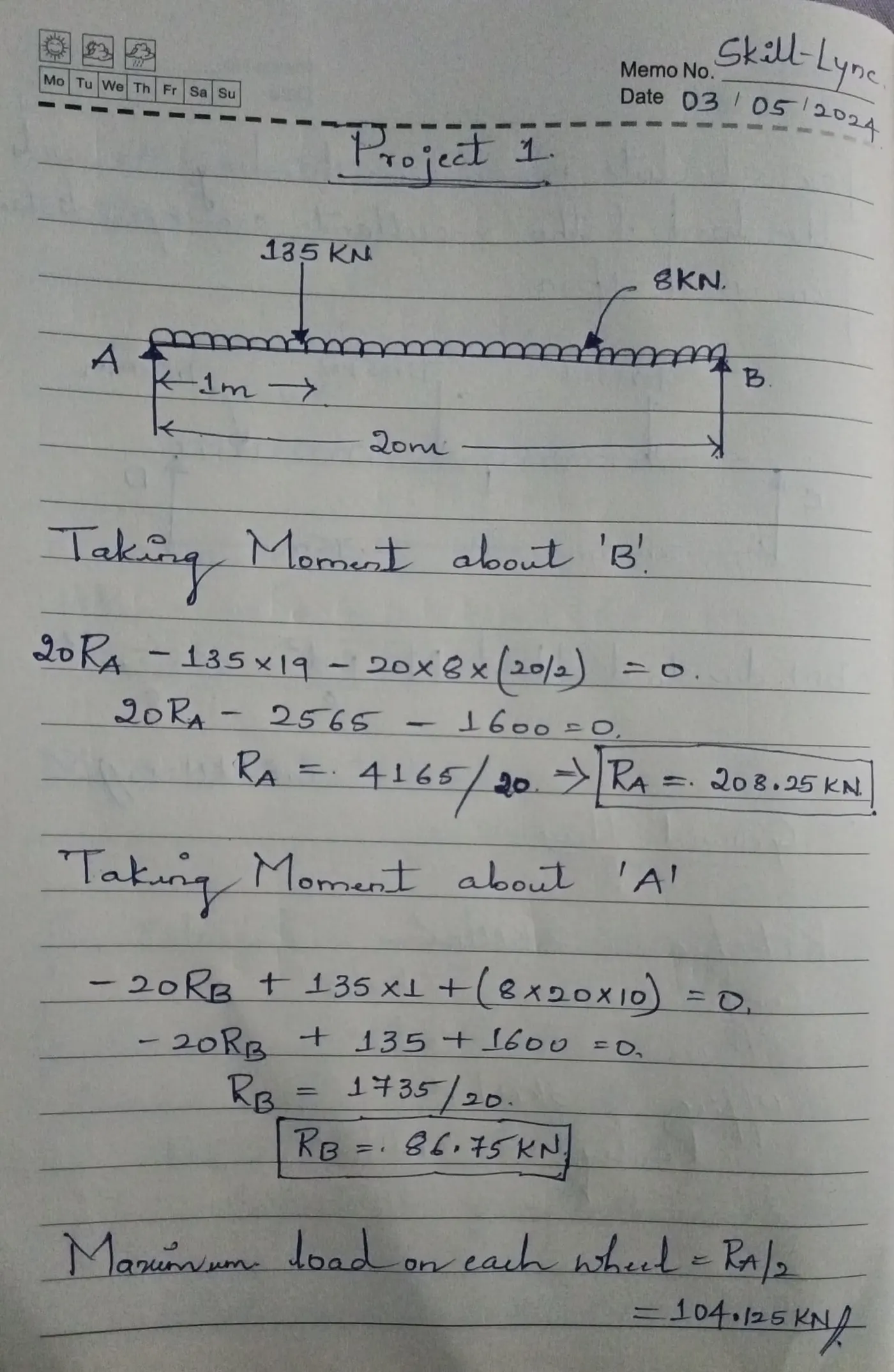
Crane weight: 100 KN
A trolley car or crab weighs 35 KN.
The crane weighs 160 KN.
The crane hook's approximate minimum approach to the gantry girder is one meter.
C/C distance of 20 meters between gantry rails
c/c distance in meters between columns
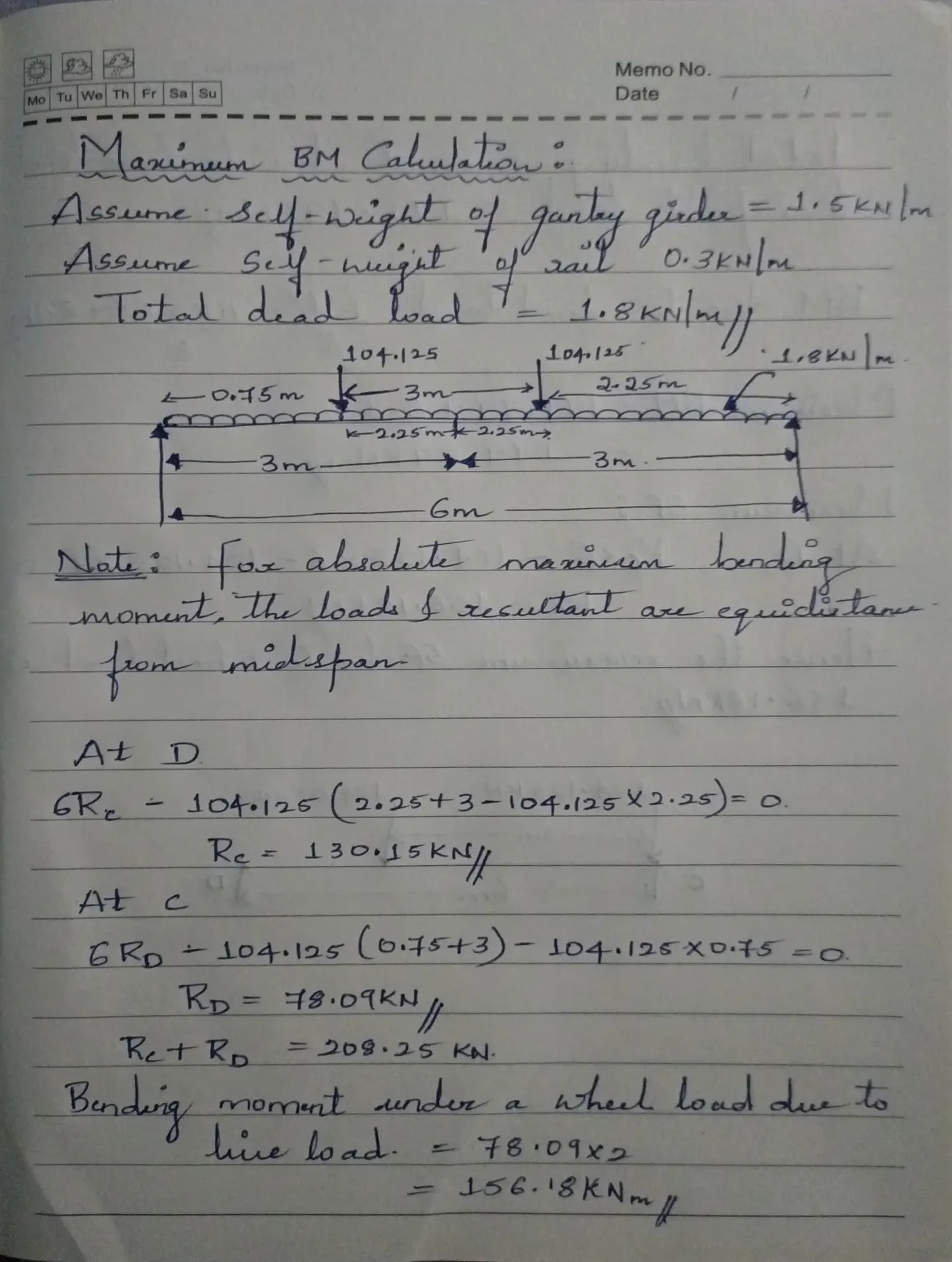
Wheelbase: 3 meters
M.O.T. crane type
Resolution:
Crane capacity plus crab weight equals the maximum point load on the crane, which is 135 KN.
Crane self-weight = 160 KN =160/20 = 8 KN
7. Lateral Forces:
5% of the weight of the crab and the weight raised is the lateral force transverse to the rails. = 0.05 x135 = 6.75 KN
Every wheel's lateral force equals 3.375 KN.
Maximum horizontal response at C as a function of lateral force
= Maximum wheel load due to vertical load / Lateral forcex response at C due to vertical load
= 3.375 x 130.15 /104.125 = 421.1 KN
Horizontal response at D as a function of lateral force
= maximum wheel load due to vertical load / lateral forcex response at D due to vertical load
= 3.375 x 78.09 (104.125)
= 2.53 KN
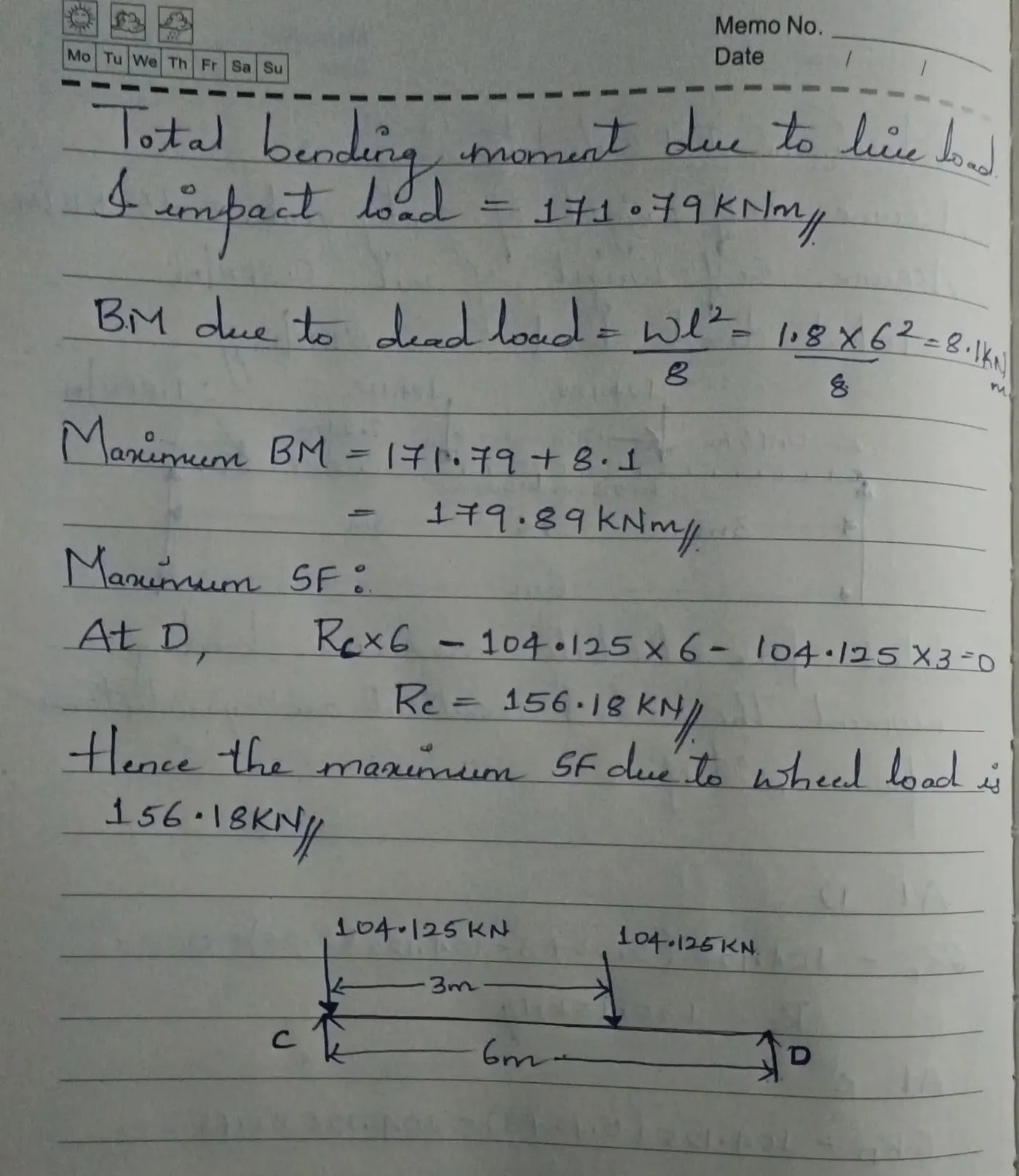
4.21 + 2.54 = 6.74 KN
Lateral load-induced bending moment = 3.375x15.18/104.125 = 5.06 KNm
Results: Following the analysis, we produced a report and a structural diagram for every participant.