Project 1_Analyze and design a steel building to 10T CRANE as per IS standard code using TEKLA STRUCTURAL DESIGNER.
Aim:
To Analyze and design a steel building to 10T CRANE as per IS standard code in TEKLA STRUCTURAL DESIGNER.Provide bracings and moment connection for lateral stability.
Procedure:
open tekla software,under file click on new
from analysing the given plan,the column placement is decided
to go setting,check once all parameter
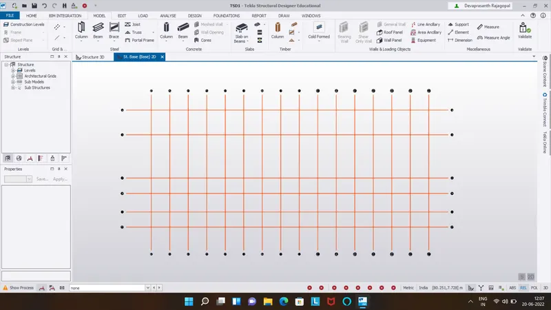
to go model,select grid line and draw the initial line
choose quick parallel lines and draw remanig grids
repeat the same for horizontal grid lines
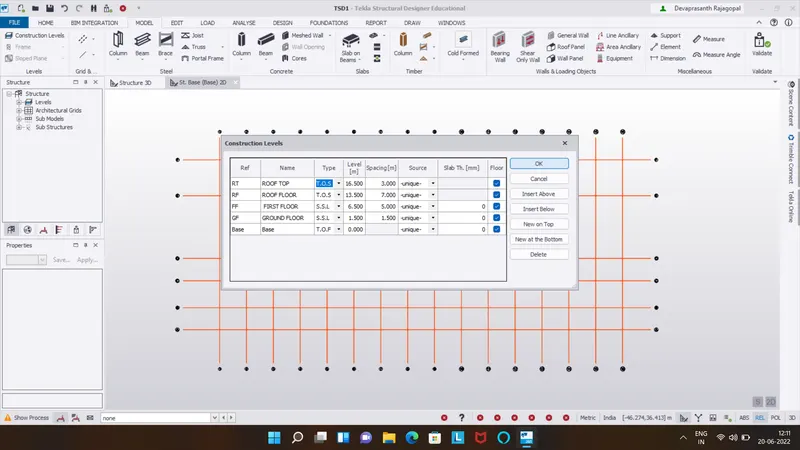
select construction levels and add the levels.
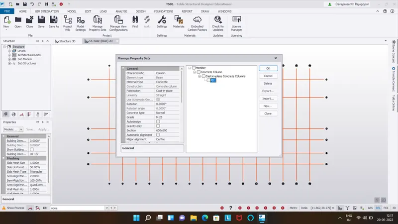
go to home>manege property>define pedestrial column.
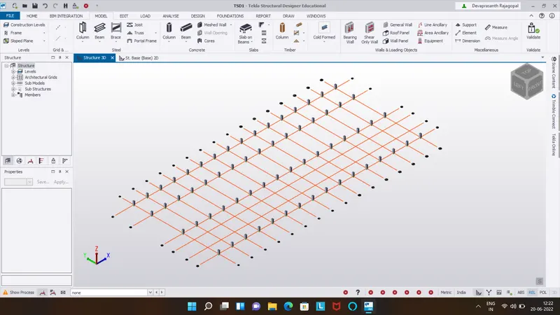
model>concrete column>click on grids to add.
define the steel column of ISMB suitable size.
from model toolbar>steel column>click on grids.
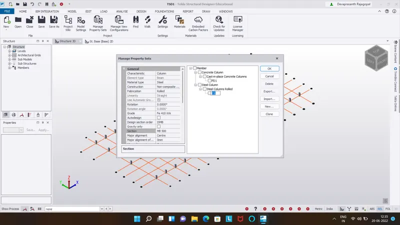
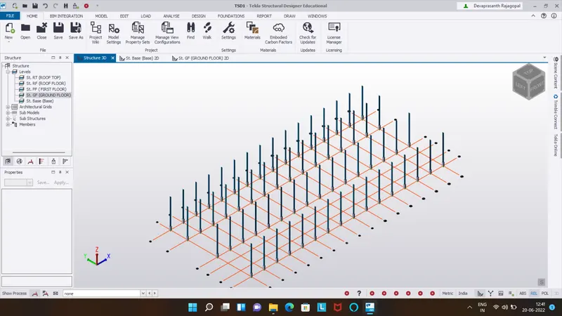
define beams for groundfloor and model beam at required sides.
similarly define for first floor and model them.
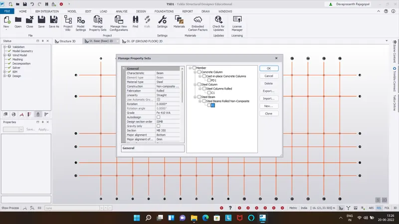
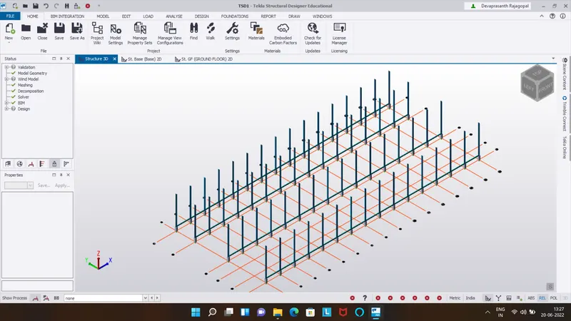
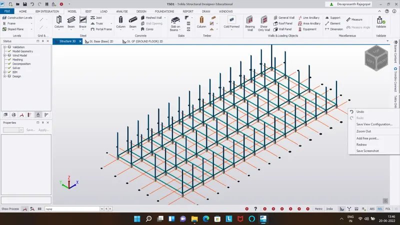
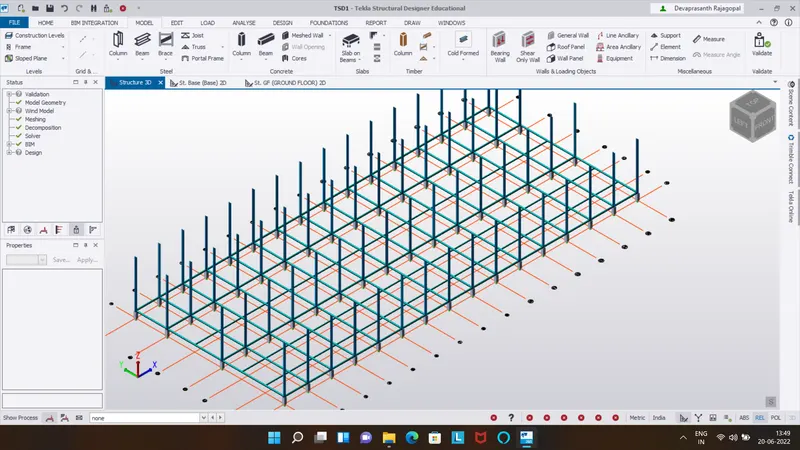
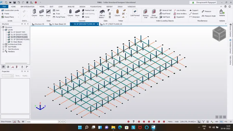
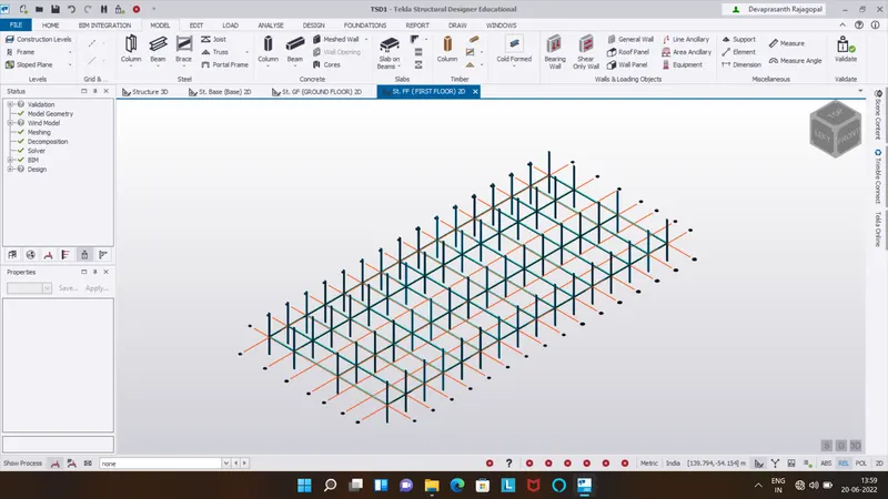
now add frames at each grid for adding braces and loading purpose.
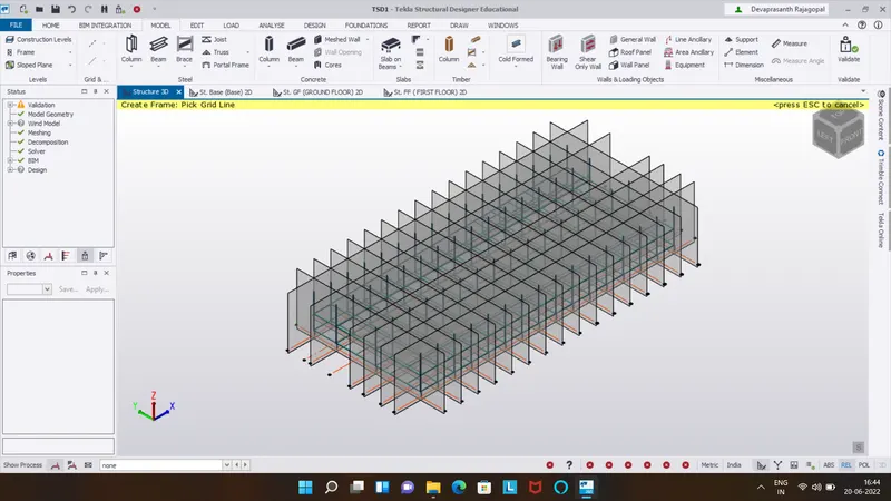
define rafter beams and model the roof truss.
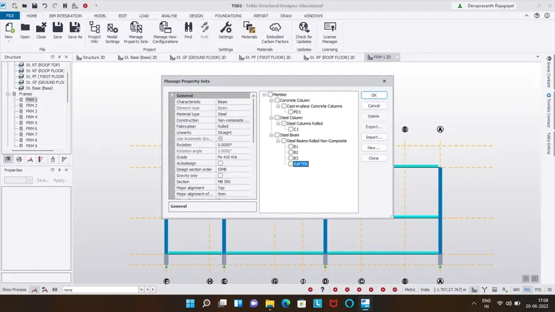
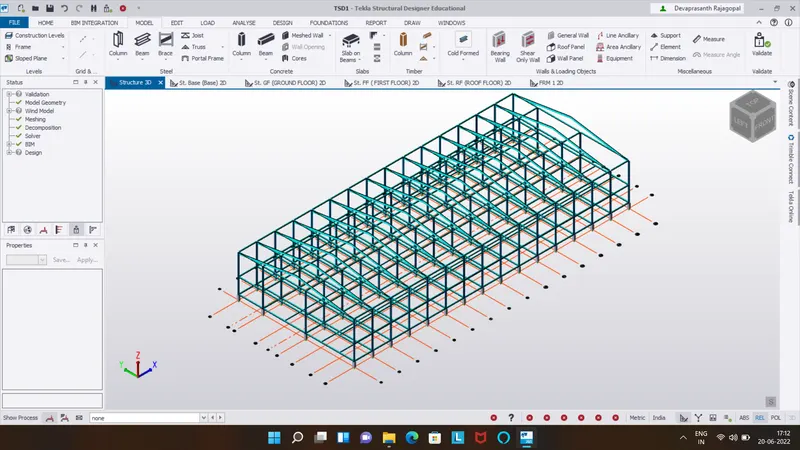
define rafter for modeling on roof.
define steel bracing and add at required places.
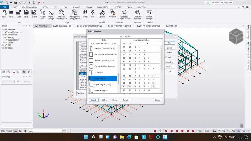
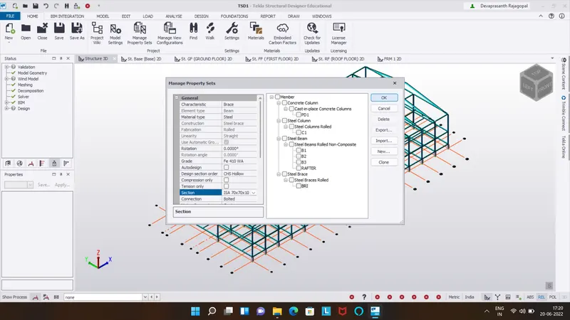
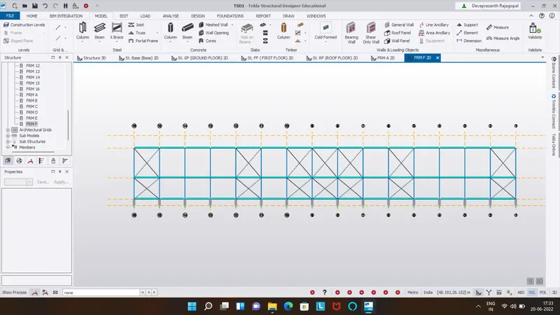
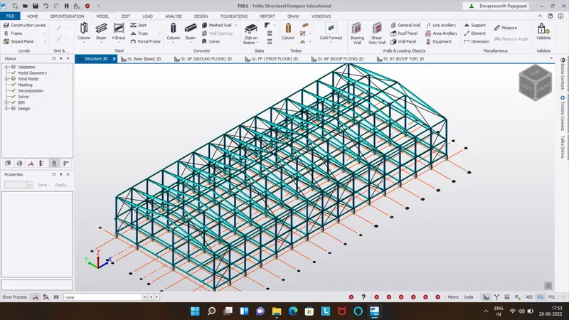
define slabs for all the floor,modeled them based on size of the beam connection.
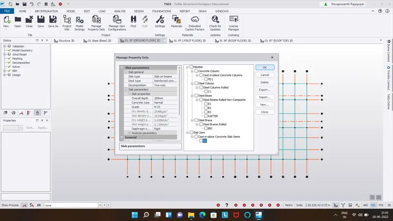
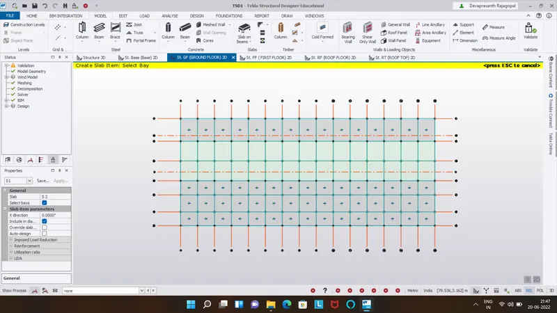
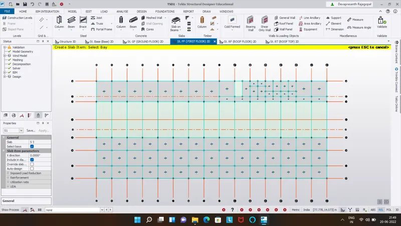
define bracket to carry the crane load and model them on first floor.
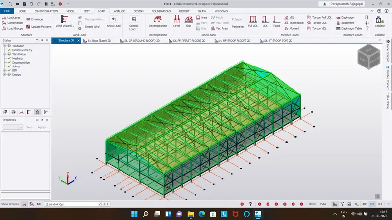
at last mdoeling part is adding wall and roof panels for ease apllication of wind load.
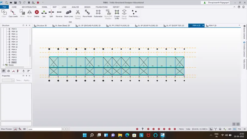
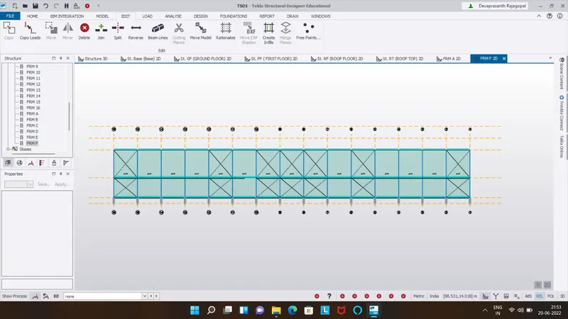
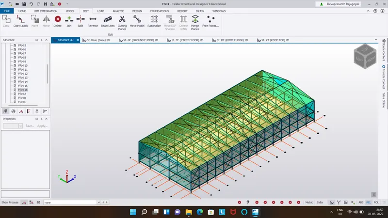
once the modeling part is done,calculation of loads,defining in software and applying them.
defin the load cases and generate load combination.
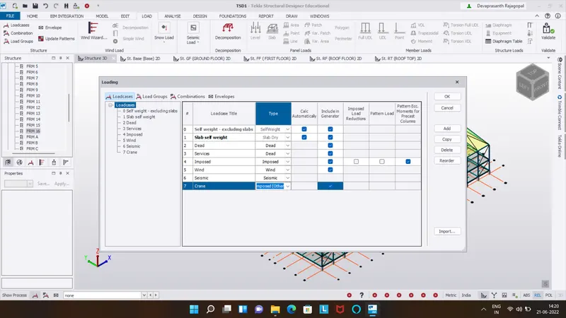
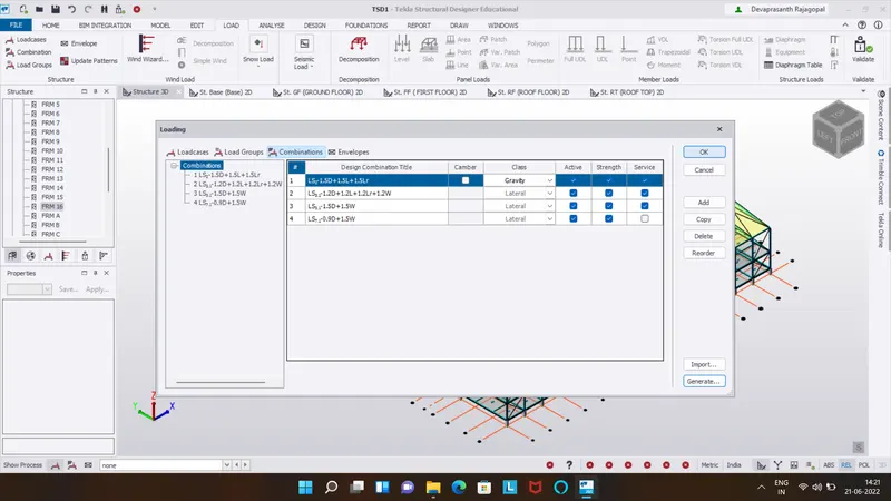
Calculation of loads:
Dead load:
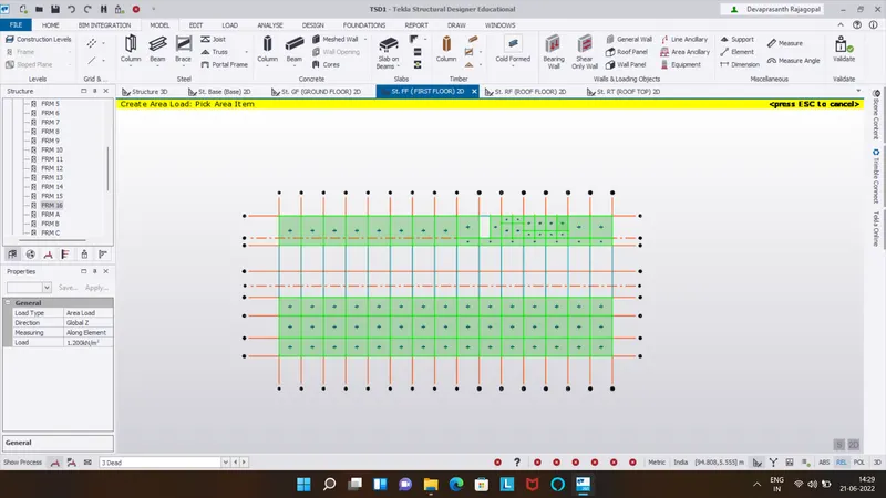
finishing load(50mm thick)-0.05x24=1.2kN/m2
brickwall+cement plaster thickNess=150mm
unit weight of brick wall=20kN/m3
brickwall load at groundfloor=.15x5x20=15kNm
brickwall load at first floor=.15x7x20=21kN/m
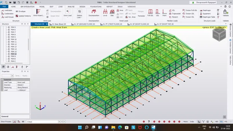
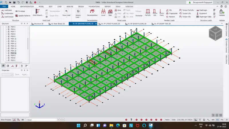
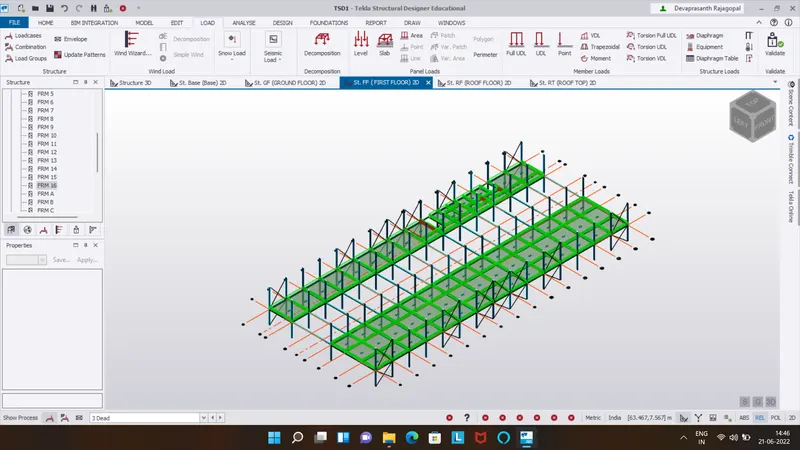
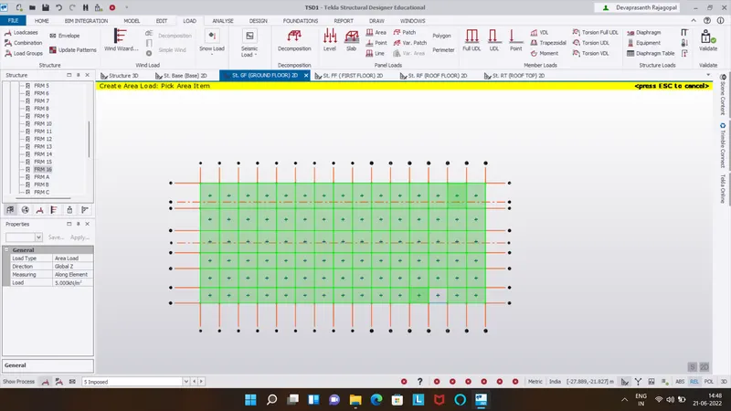
set the load as dead and select ground floor,in load toolbar>select area load and enter 1.2 as finish load.
for brickwall load,select full udl load and enter value as per calculation.
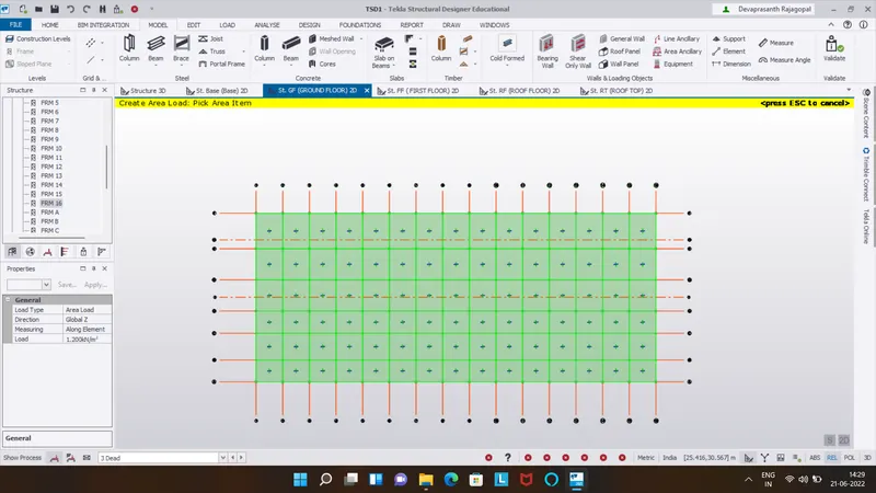
Live load for each unit as per IS 875:part 2-
office room-3kN/m2
restroom/toilet=2kN/m2
store room=5kN/m2
staircase=5kN/m2
conference room=5kN/m2
equipment room=10kN/m2
flat roof without access=0.75kN/m2
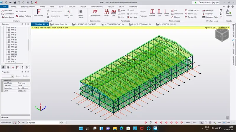
Select imposed load,area load from load toolbar and enter the value as per code.
wind load calculation:
Basic wind speed, Vb = 39m/s.
Terrain category = 2
Class of structure = A
One horizontal dimension of structure, L = 90m
Another horizontal dimension of structure, N = 38m
Eaves level height of structure, h = 12m
Ratio of wall and Roof Co-efficient
Wall, L/W = 2.36
Wall,h / w = 0.31
ROOF, h / w = 0.31
As per reference of IS 875. Part-3, Table -5.
external pressure co-efficient (CPe) =
To find Design Wind pressure (PZ)
Pz = 0.6*Vz^2.
To find Vz,
Vz= Vbxk1xk2 k3xk4
Therefore,
As we take value of k1, k2, k3, k4 from IS 875.
KI = 1 under basic wind speed)
K2=1.0 (height upto 10m)
K3=1
K4 = 1.15 (for industrial building)
Vz =39 *11*1*1.15
Vz = 44.85 m/s
Pz =0.6 (44.85) 2
Pz =1.207 kN/m^2.
according to the clause 7.3.2.2,the internal coefficient is 0.7 and -0.75
to find wind load for wall,
| for wall face A,+y | Cpi | -Cpi |
| height at different level(m) | 12 | 12 |
| external cofficient pressure(cpe) | 0.7 | 0.7 |
| internal cofficient pressure(cpi) | 0.7 | -0.7 |
| net pressure coefficient(cpe-cpi) | 0 | 1.4 |
| design wind pressure for wall(kN/m2) | 1.25 | 1.25 |
| wind load on wall | 0 | 1.75 |
| for wall face B,+y | Cpi | -cpi |
| height at different level(m) | 12 | 12 |
| external cofficient pressure(cpe) | -0.25 | -0.25 |
| internal cofficient pressure(cpi) | 0.7 | -0.7 |
| net pressure coefficient(cpe-cpi) | -0.95 | -0.7 |
| design wind pressure for wall(kN/m2) | 1.25 | 1.25 |
| wind load on wall for | -1.187 | 0.582 |
| for wall face C and D | Cpi | -cpi |
| height at different level(m) | 12 | 12 |
| external cofficient pressure(cpe) | -0.6 | -0.6 |
| internal cofficient pressure(cpi) | 0.7 | -0.7 |
| net pressure coefficient(cpe-cpi) | -1.3 | 0.1 |
| design wind pressure for wall(kN/m2) | 1.25 | 1.25 |
| wind load on wall for | -1.625 | 0.125 |
for roof,of slop - 18 degree
h/w = 0.31
| for wall face C and D | Cpi | -cpi |
| height at different level(m) | 12 | 12 |
| external cofficient pressure(cpe) | -0.4 | -0.4 |
| internal cofficient pressure(cpi) | 0.7 | -0.7 |
| net pressure coefficient(cpe-cpi) | -1.1 | 0.3 |
| design wind pressure for wall(kN/m2) | 1.25 | 1.25 |
| wind load on wall for | -1.275 | 0.375 |
| for wall face C and D | Cpi | -cpi |
| height at different level(m) | 12 | 12 |
| external cofficient pressure(cpe) | -0.4 | -0.4 |
| internal cofficient pressure(cpi) | 0.7 | -0.7 |
| net pressure coefficient(cpe-cpi) | -1.1 | 0.3 |
| design wind pressure for wall(kN/m2) | 1.25 | 1.25 |
| wind load on wall for | -1.375 | 0.375 |
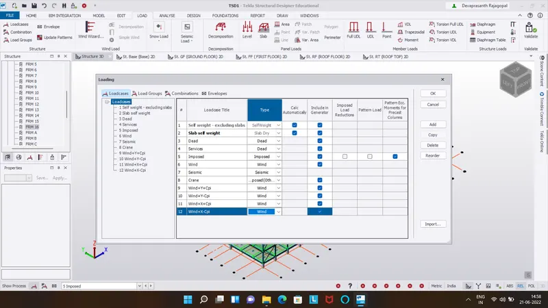
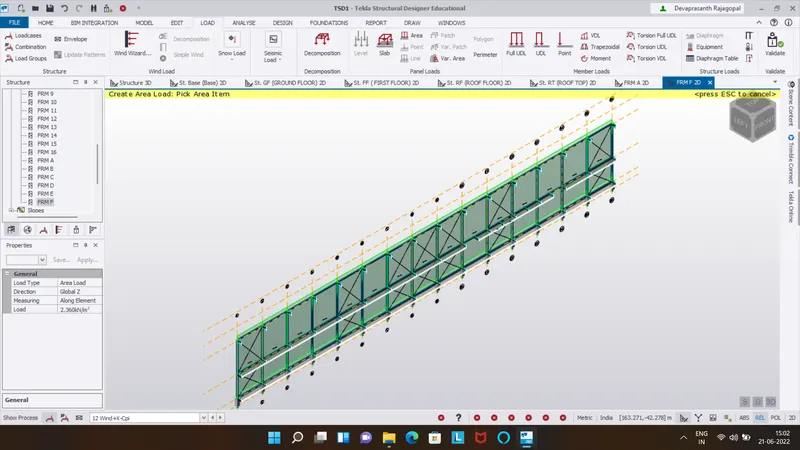
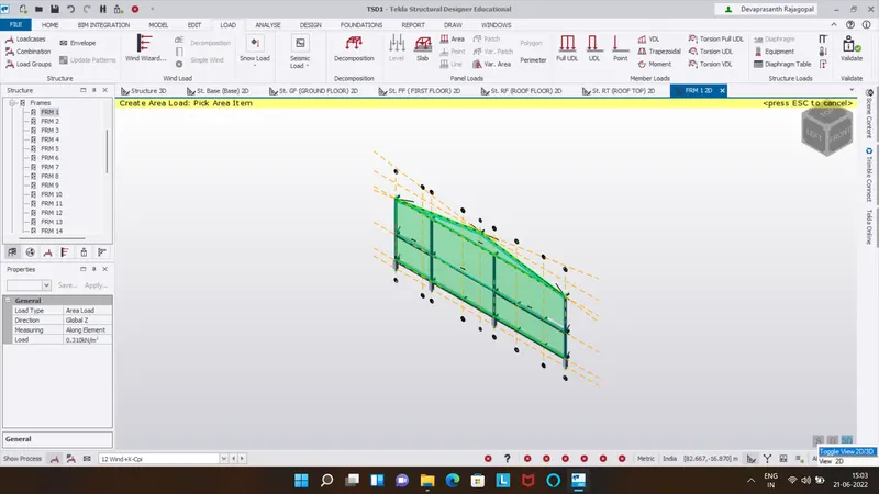
For wind load application,create load cases.
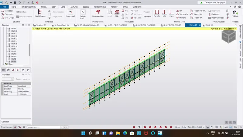
select particular load case,+y,-y,+x and -x combination and enter the value.
select are load,click on wall/roof panel
Crane load calculation:
Given:
crane capacity = 100kN
Weight of the crab = 35kN
Weight of the crane = 160kN
Maximum hook approach - 1m
Wheel base-3m
Distance between c/c gantry rails = 20.0 m
Distance between c/c gantry column -6 m
Maximum wheel load
Maximum point load on the crane - crane capacity weight of the crab 100 35-135kN
Self-weight of the crane = 160kN
- 160/20 - 8 kN
Taking Moment about B
RA * 20 - 135 * 19 - 8 * 20 * 10 = 0
RA= 208.25 kN
Taking Moment about A
RBX 20 -135 X 1-8 x 20 x 10 =0
RB=86.75 kN
Maximum wheel load on each wheel - RA/2=104.125 kN
Maximum Bending Moment:
Assume self-weight of gantry girder as 1.5 kN/m
Assume self-weight of rail as 0.3 kN/m
Total dead load - 0.3 + 1.5 = 1.8kN /m
moment at D
Rc * 6 - 104.125(2.25 + 3) - 104.125 * 2.25 = 0
Rc = 130.15KN
moment at C
RDX 6-104.125 (0.75 +3) -104.125 X 0.75 -0
RD = 78.09KN
Rc + RD = 208.25KN
Bending Moment under a wheel load due to live load= 78.09 X 2= 156.18 KNm
Bending moment due to impact -0.10 X 156.18 = 15.618 KN m
Total bending moment due to live load and impact load = 171.79 KN m
Bending moment due to dead load W12/8-1.8 X 6x6/8 = 8.1 kNm
Maximum bending moment = 171.79 * 8.1 = 179.89KNm
Maximum shear force:
moment at D,
Rc * 6 - 104.125 * 6 - 104.125 * 3 = 0
Rc = 156.18KN
Hence the Maximum shear force due to wheel load is 156 18 KN
Lateral Forces:
Lateral force transverse to ralls ( 5% of the weight of crab and weight lifted)=0.05x135=6.75 KN
Lateral forces on each wheel=3.375 KN
horizontal reaction due to lateral force by proportion at C=3.375 X 130.15/104.125=4.21kN
horizontal reaction due to lateral force by proportion at D=3.375 X 78.09/104.125=2.35kN
now to add crane load for girder designed in roof,select crane load.
from load toolbar,select point load and enter all x,y and z value from calcuation and click on girder.
seismic load is calculated in software using seismic wizard.
for analysis,set the building modeling as 1.
1st order analysis is done
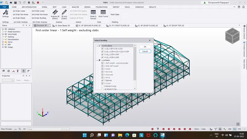
Given plan is analysed and column column is decided.
structure is modeled using model toolbar and property of element is defined in property manager.
Load are calculated and applied on the structure.
Model is analysed and failure beam are resized.
Result: