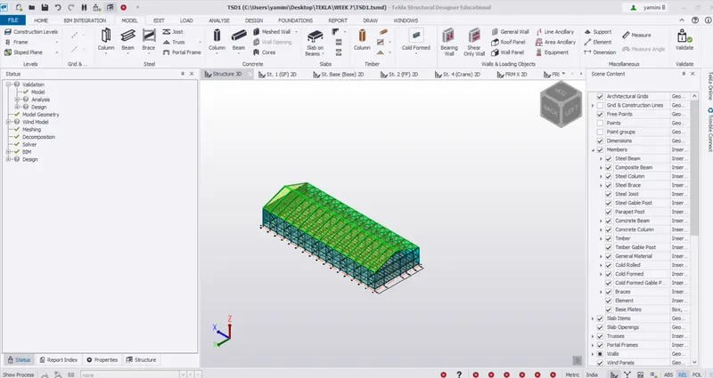
Project 1_Analyze and design a steel building to 10T CRANE as per IS standard code using TEKLA STRUCTURAL DESIGNER.
- Analyze and design a steel building to 10T CRANE as per IS standard code in TEKLA STRUCTURAL DESIGNER.
- Refer the attached plan and elevation. Provide bracings and moment connection for lateral stability.
- Consider dead, live, equipment and wind loading. Consider the brick wall loading for 150mm thick and 1.5 KN per sq m for wall and roof cladding.
- Assume wind loading basic speed as 39m/s
- Report of each member to be generated and extract drawings of structural plans from the software
AIM : To analyze and design a steel building to 10T CRANE as per IS code in TEKLA STRUCTURAL DESIGNER.
INTRODUCTION :
Loads cases and load combinations are generated, assigned for the structure using tekla and validation of those loads is an important part of Tekla Structural Designer as it ensures a valid model for the analysis and design routines. Imposed Loads are assigned according to IS 875 Part 2
Load calculation :
Dead Load calculation
Slab load : model slab in software
Finishes : 50mm x 24 KN/m^3 = 0.05 x 24 = 1.2 KN/m2
Brick wall width = 155mm
Unit weight = 20 KN/m^3
Floor height (Ground floor to First floor) = 5m
Brick wall loading for ground floor = 20 x (150/1000) x 5 = 15 KN/m
Floor height (First floor to roof ) = 7 m
Brick wall loading for first floor = 20 x (150/1000) x 7 = 21 KN/m
Roofing load based on purlin size :1.5KN/m^2
Ceiling loading 0f 0.3KN per sq m
Live loads taken as per IS 875 Part 3
Work areas without machinery/equipments = 2.5KN/m^2
Work areas with machinery/equipments (Heavy) = 10KN/m^2
Staircase : 4KN/m^2
Toilets : 2KN/m^2
Canteen : 3KN/m^2
Store room : 2.4KN/m^2
Conference room : 4KN/m^2
Meeting room : 4KN/m^2
Office room : 4KN/m^2
Manager room : 4KN/m^2
Corridor : 4KN/m^2
Roof access not provided is taken as : 0.75KN/m2
Crane load = 10T
Wind load calculation :
Wind speed taken as 39m/s
Terrain category is given as 2
Vb = Basic wind speed which is given as 39m/s
Normally basic wind speed is selected from appendix A of code book IS 875 III which is given based on wind speed in various cities
Design wind speed Vz= Vb*K1*K2*K3*K4
Where Vz depends on risk level, terrain roughness, height, size of structure, local topography
K1 = Probability factor
It is taken from table 1 of IS 875 III
Life of structure is taken as 50 yrs and wind speed is given as 39m/s. Based on this K1 =1
K2 = Terrain, height, structure factor which is taken from table 2 = 1.05
K3 = Topography factor which is taken as 1 (θ<3 = 1 and θ>3 = 1 to 1.36)
K4 = Importane factor for cyclonic region K4 is taken as 1.15
Where K4 = 1.3 Structure for post cyclonic importance
= 1.15 Industrial structure
= 1 All other structure
- Design wind speed Vz = Vb x K1 x K2 x K3 x K4 = 39 x 1 x 1.05 x 1 x 1.15 = 47m/s
- Design wind pressure = Pz = 0.6 x Vz^2 = 1330N/m2 = 1.33KN/m2
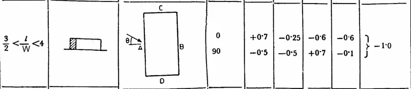
- length = 90m, Width = 48.925m, Height = 20.
- L/W = 1.84 and H/W = 0.4
- External pressure coefficients for wall is taken from table 5 IS 875 III(h/w <1/2)
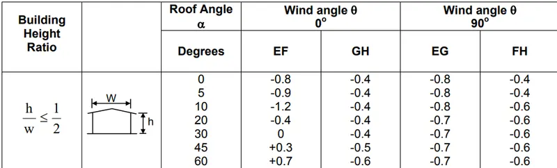
- Roof angle is calculated (20 degree)and based on roof angle external pressure for roof is calculated based on table of IS 875 II
PROCEDURE :
- Open tekla software.
- Click on "Materials" and check for necessary materials and reinforcement available for structure, Example M30, Fe500, sizes of bars etc
- Similarly check settings for Design code, Design settings, Scene content etc
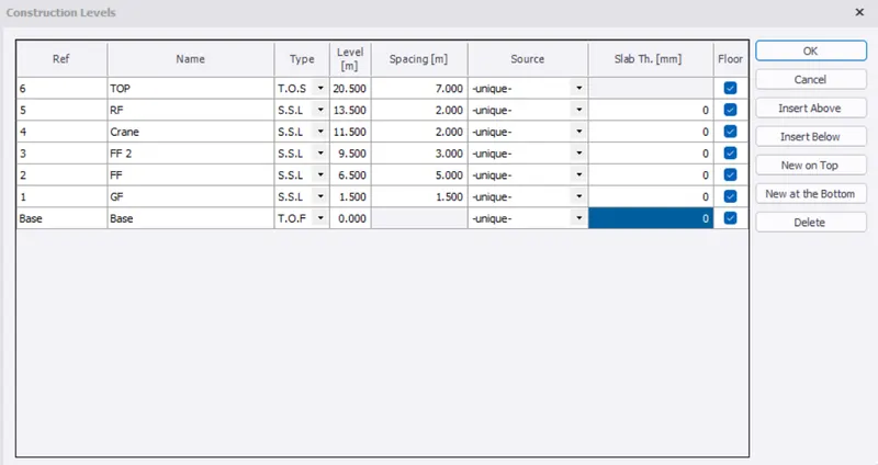
- Now add construction levels as shown below :
- Now add grids
- Go to "Model", In grids select "Rectangular wizard"
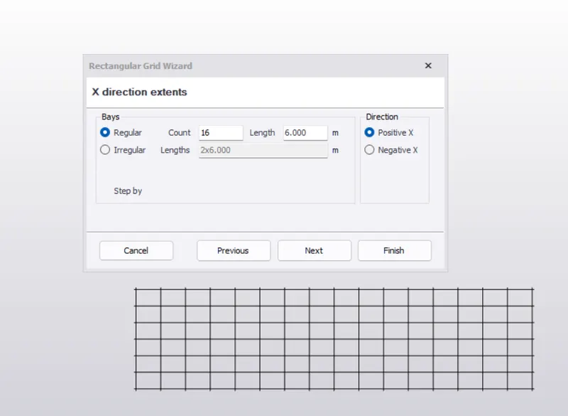
- Enter "X" coordinates as shown below
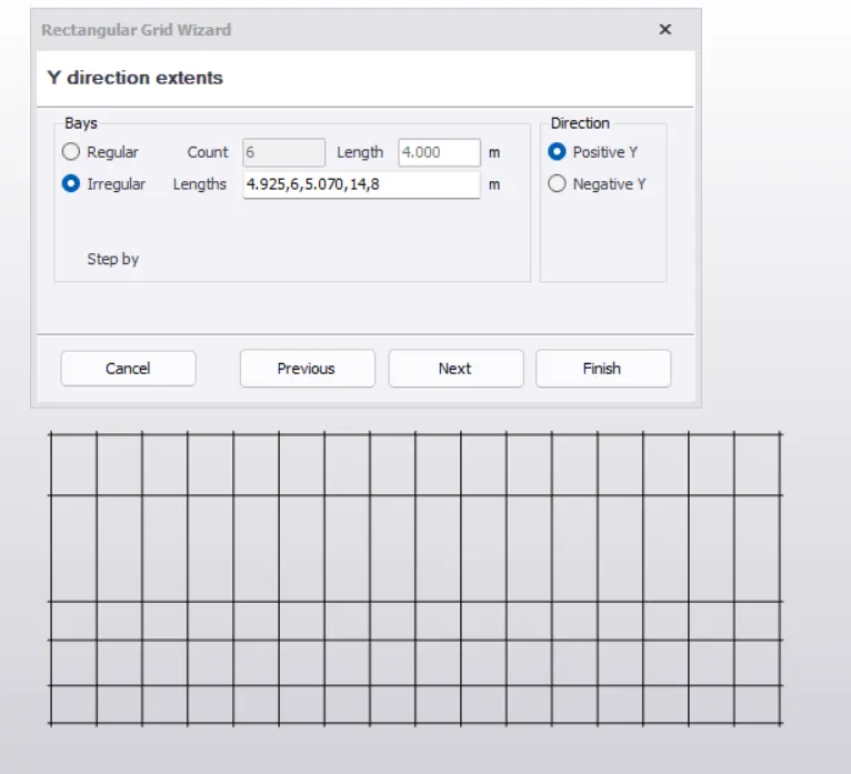
- Enter "Y" coordinated as shown below
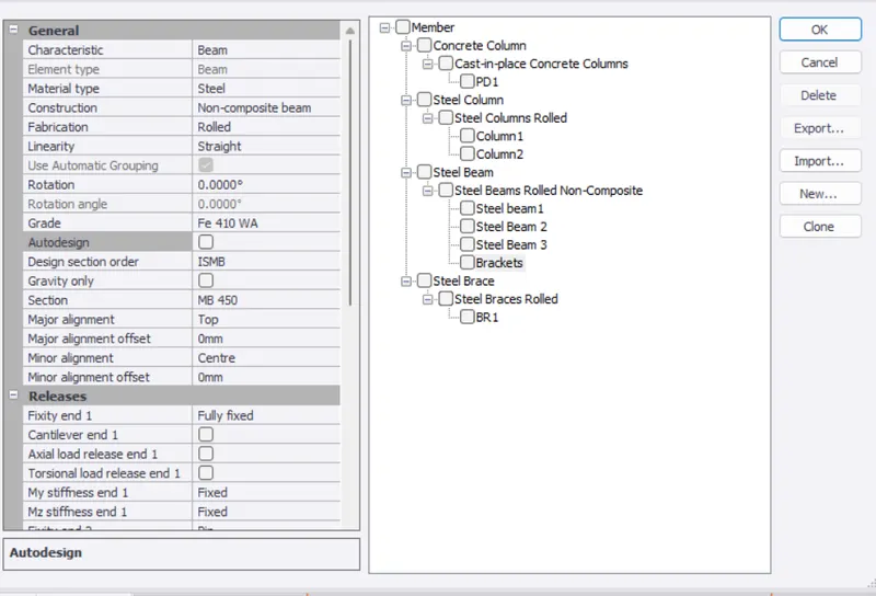
- Add Pedestal
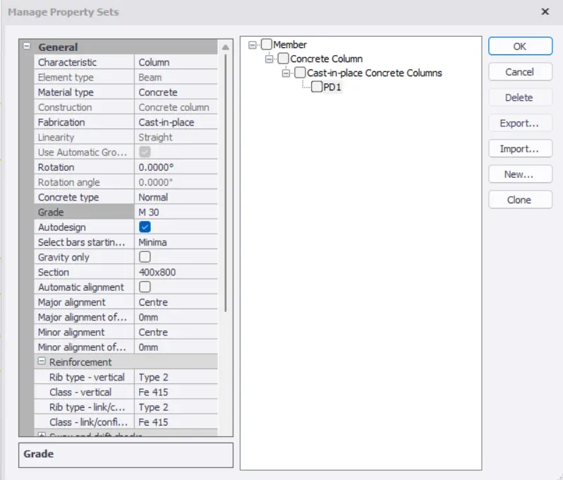
- Select "Manage property sets"
- Click on "Add"
- Select Concrete column
- Change its name to "PD1"
- Change properties of pedestal : Select grade as M30, Change size to 400x800, Set major alignment to Centre
- Click ok
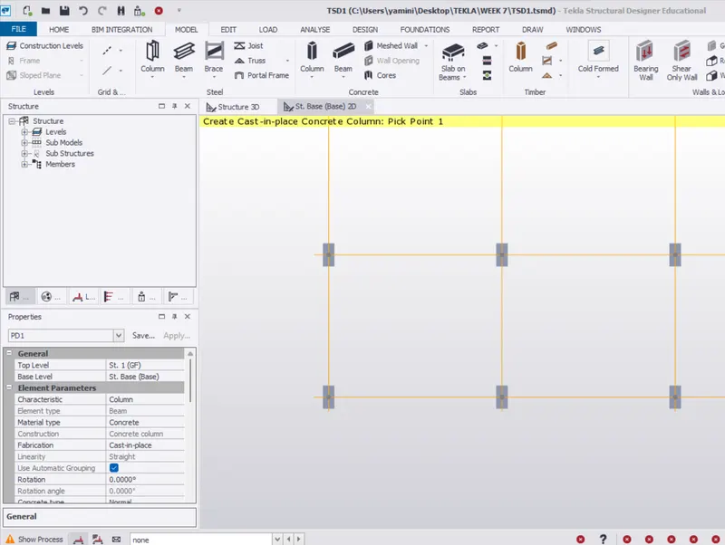
- Go to "Model"
- Select concrete column
- Add Steel column
- Select "Manage property sets"
- Click on "Add"
- Select Concrete column
- Change its name to "Column1"
- Change properties of pedestal : Select Section as ISMB600, Set major alignment to Centre and Fixity to Pinned
- Click ok
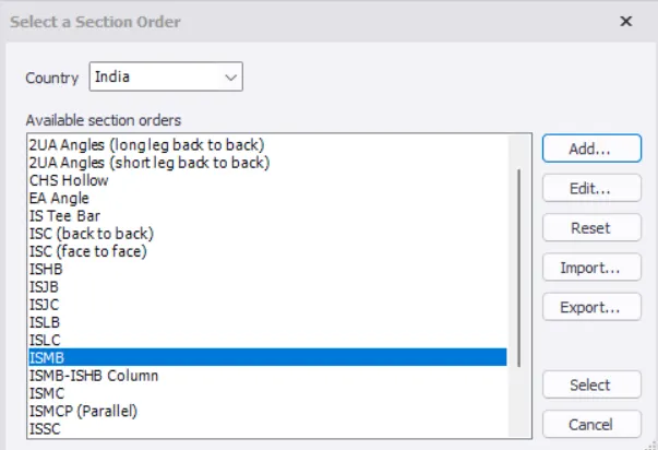
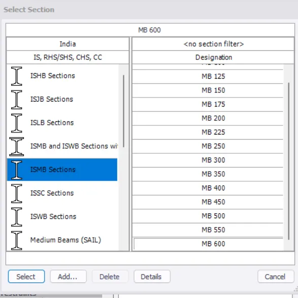
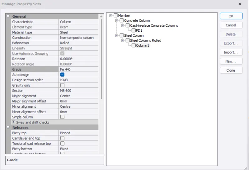
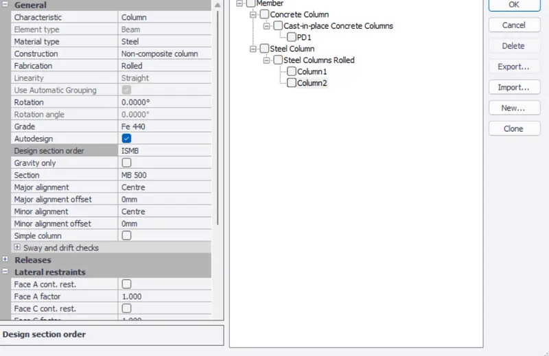
- Similarly create Steel column 2
- Steel beams ISMB450, ISMB350,ISMB300
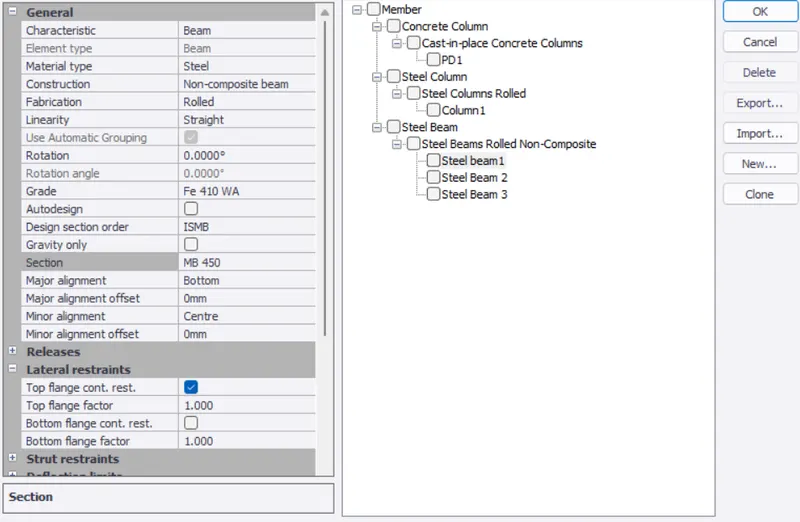
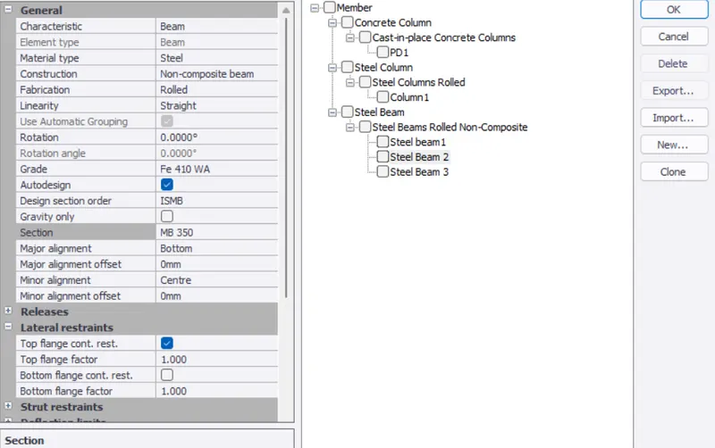
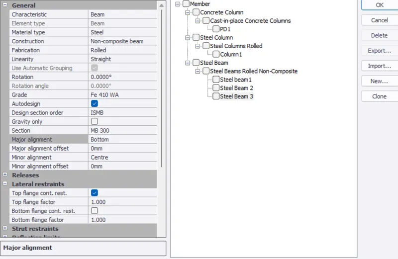
- Draw Slabs on First floor and second floor
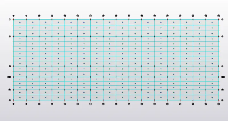
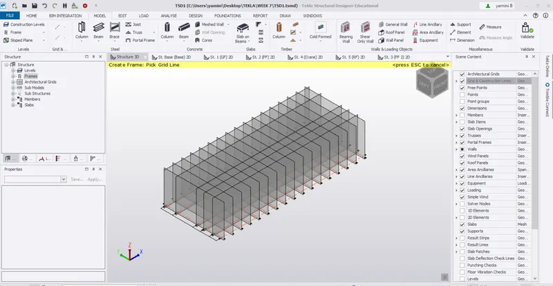
- Assign frames to grids
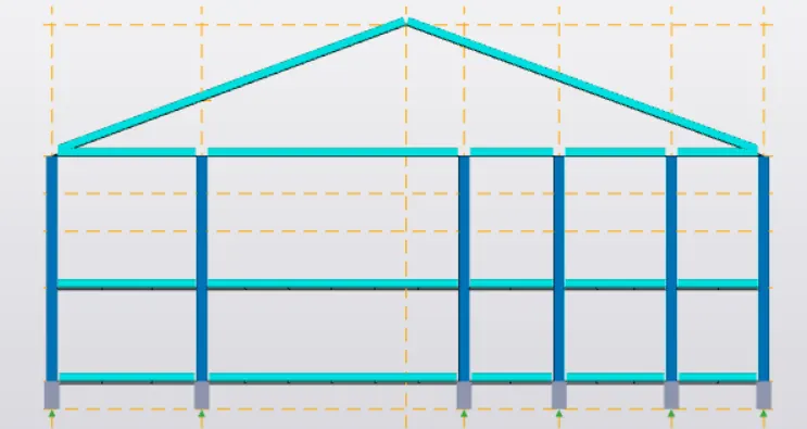
- Add Rafter and Ridge beams
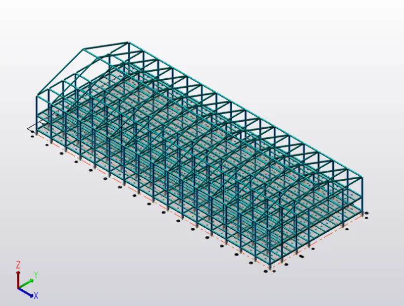
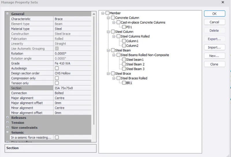
- Add new member : Steel brace
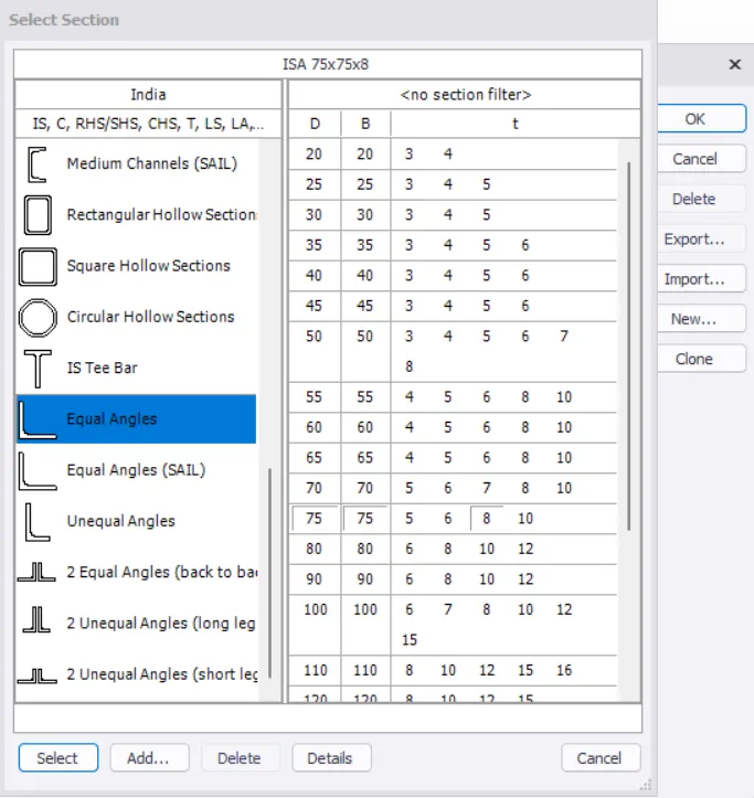
- Assign section as : Equal angle 75x75x8 size and Connection as bolted, Untick : Autodesign
- Model is validated once and combination of loads are defined.
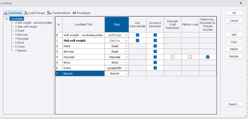
- Select "Load cases" and add load cases
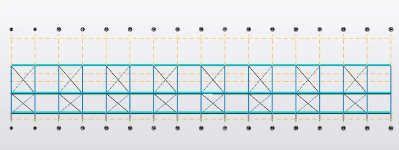
- Select brace - X from model and draw bracings
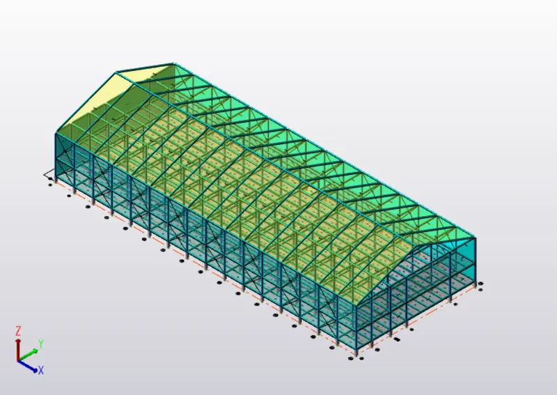
- Add wall panels and roof panels
- Generate Load combinations
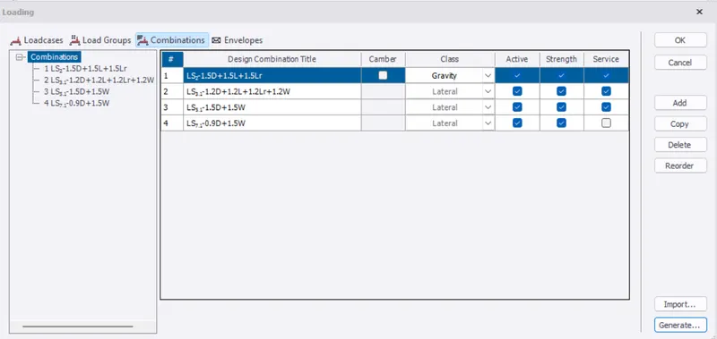
- Select dead load at the bottom
- Select area load = 1.2KN/m2 in ground floor and first floor and apply it
- Select Full udl for brick load = 15.5kn/m2 for ground floor, load of 21.7 for first floor and apply it
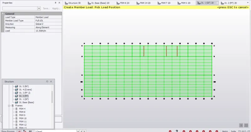
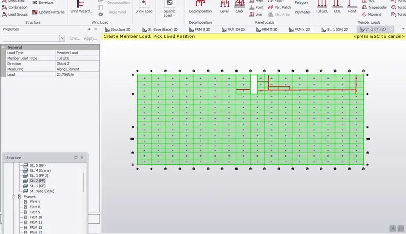
- Apply dead load of 1.5kn/m2 on roof panles
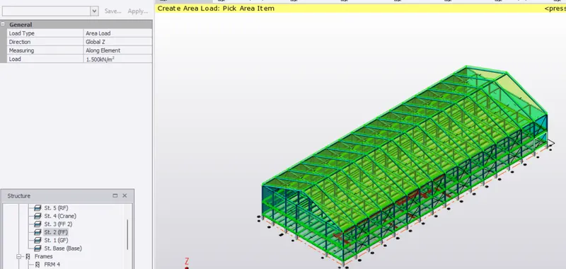
- Now apply imposed loads as per IS 875 Part 3 on the floors and roof (0.75KN/m2)
- Go to "crane level"
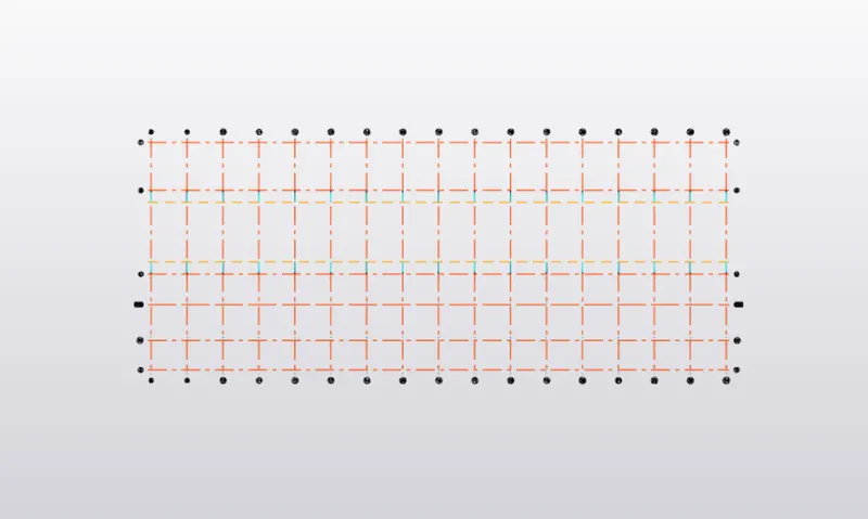
- Draw beams (brackets) as shown below at a distance of 2000mm
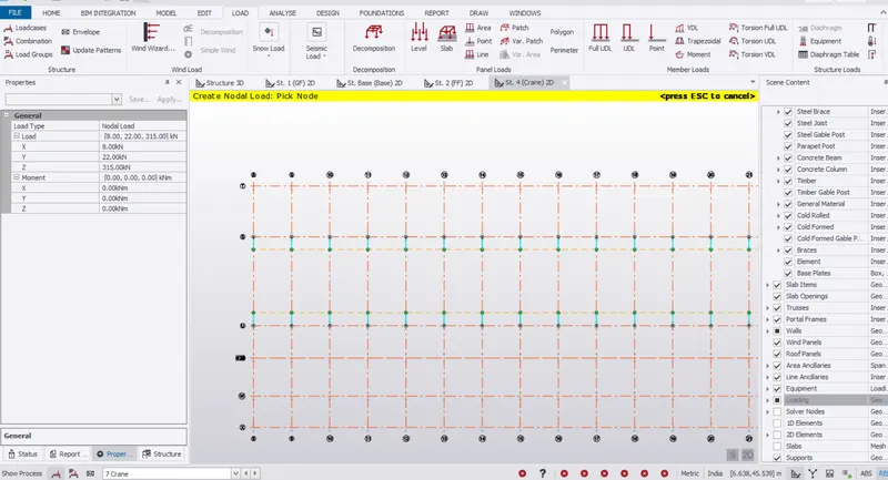
- Select crane load at the bottom
- Now select point load in member load
- In properties enter X= 8KN, Y=22KN, Z=315KN and apply it on brackets
- Now select Load cases
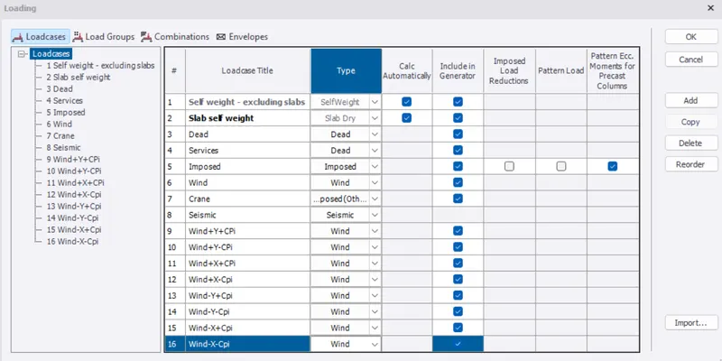
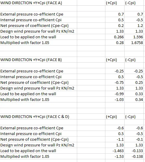
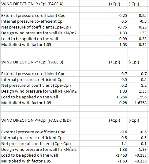
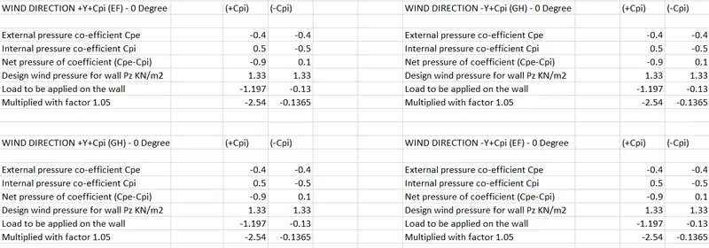
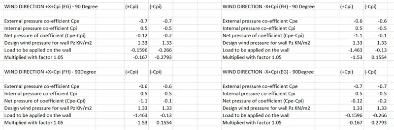
- All these wind load combinations are applied on the model
RESULTS :
Validated model