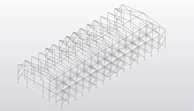
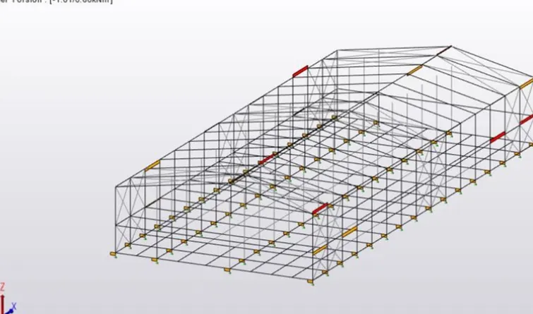
Project 1_Analyze and design a steel building to 10T CRANE as per IS standard code using TEKLA STRUCTURAL DESIGNER.
Aim - To analyze and design a steel building to 10T crane as per IS standard codeusing Tekla structural Designer
Procedure -
- Initially open the Tekla Structural Designer Software
- Click on New option to create new model
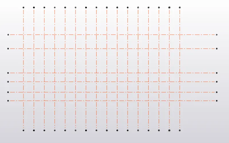
- Using Grid lines and Quick parallel grid line option horizontal grids and vertical grids was drawn.
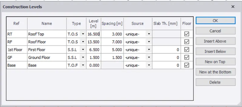
- In the model toolbar select construction level dialogue box
- Construction level dialogue box appears and name each level as Base,Ground floor,First floor,Roof floor and Roof top and also assigned the height to each level.
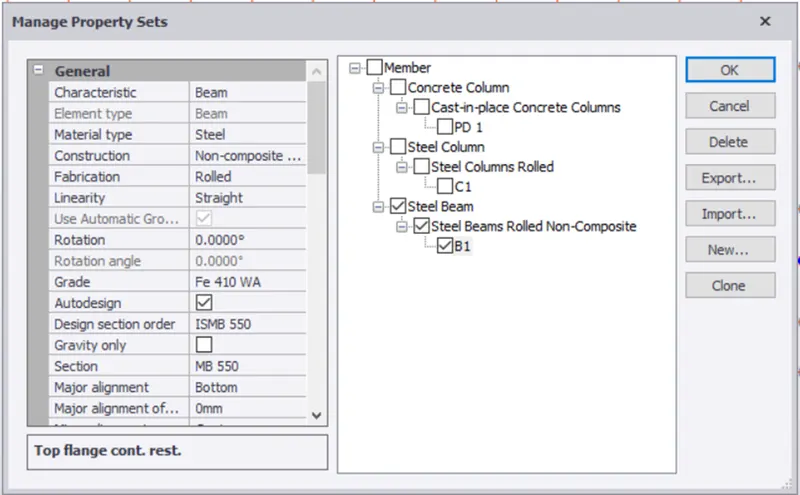
- Now to add pedestal columns in gthe Home menu click on Manage Property setd option and the manage property sets dialogue box appear
- Click on New followed by members ans select concrete column
- Rename it as PD1 and also apply properties
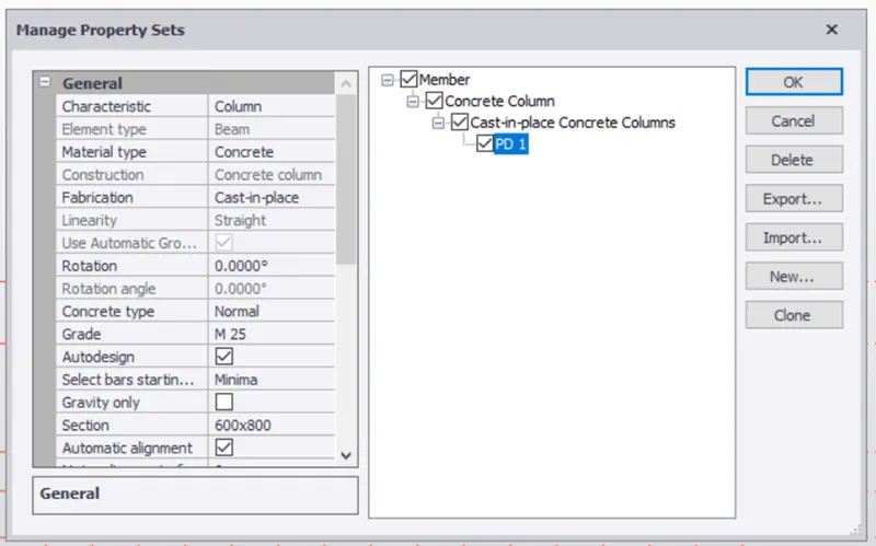
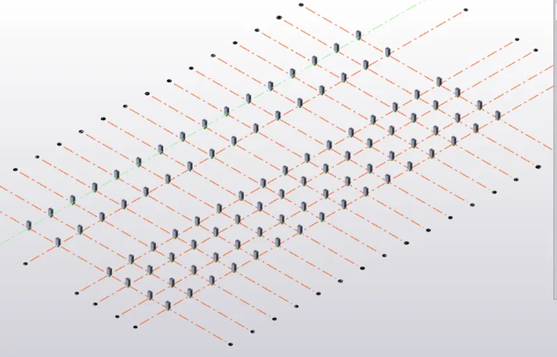
- Now using column option in the ribbon tab under model menu,Column was placed at locations as required.Column was placed at base floor upto ground floor
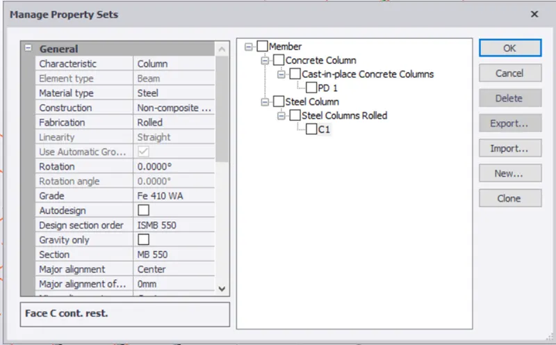
- Similarly,creats steel column under manage property sets option
- Rename it as C1 and also apply properties
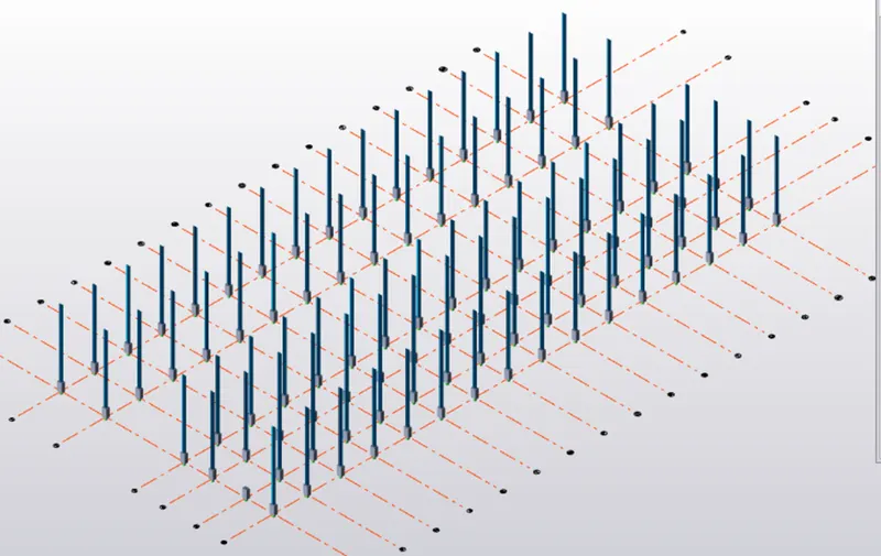
- Now using column option in the ribbon tab under the model menu column was placed at locations as required.Column wa placed at Ground floor upto Roof floor
- Similarly,create beam under manage property setd option
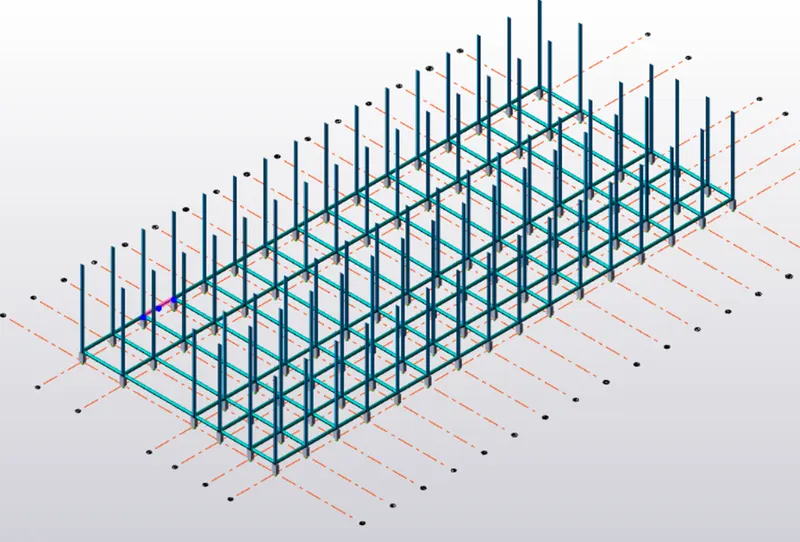
- Now using beam option in the ribbon tab under the model menu beams was placed at locations as required
- Beams at Ground level
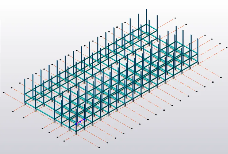
- Beam at first floor
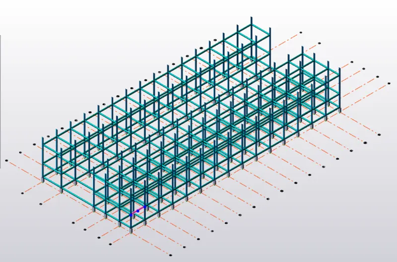
- Beam at Roof floor
- Rafter beam was designed using manage property set option,Click on New followed by members and select steel beam
- Rename it as Rafter and apply properties
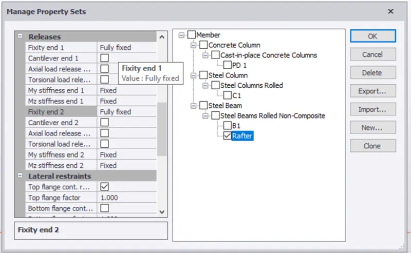
- Now Rafter beam was applied using the beam option in the ribbon tab under the model menu and beams was placed at locations as required
- Both the ends of Rafter was set fully fixed
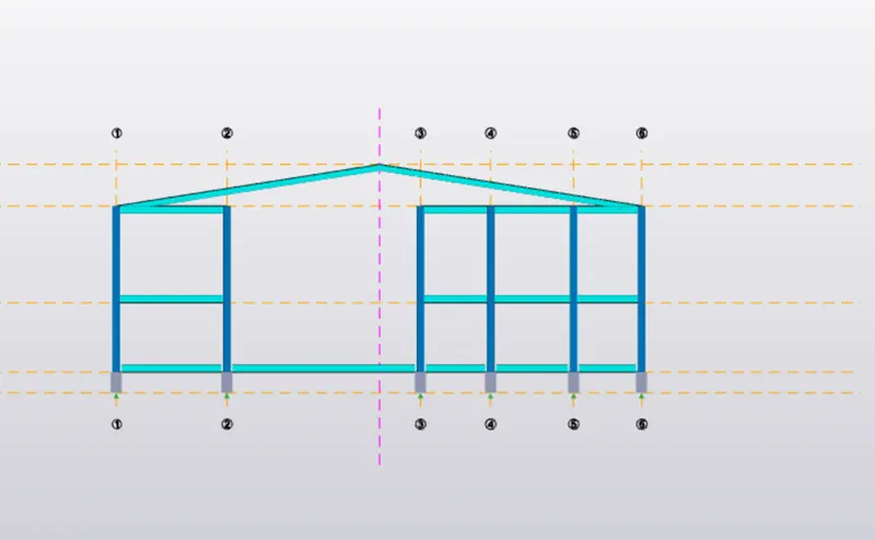
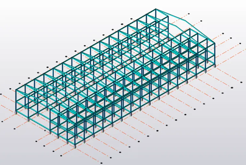
- Steel bracing was designed next for that click on manage property sets option and manage property sets dialogue box appear.Click on new followed by members and select Steel Brace .
- Reanme it as Bracing and apply properties
- Also select section size of ISA 75X75X8 for designing
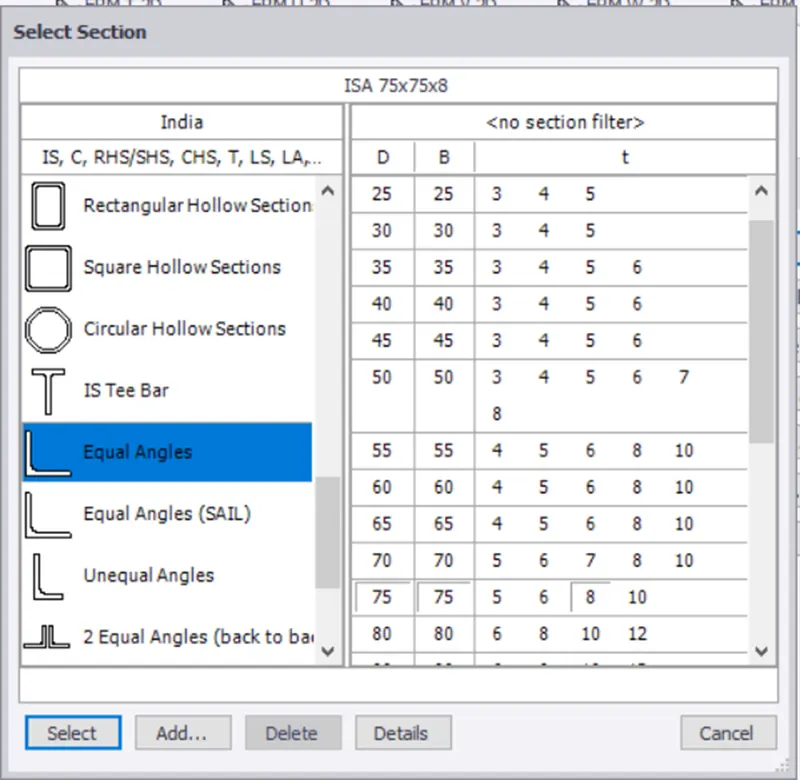
- Now steel brace were applied using the brace option in the ribbon tab under the model menu and braces was placed at locations by selecting opposite corners points.then select X brace option and drawn
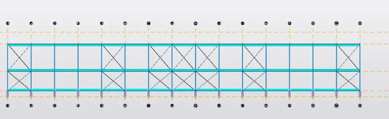
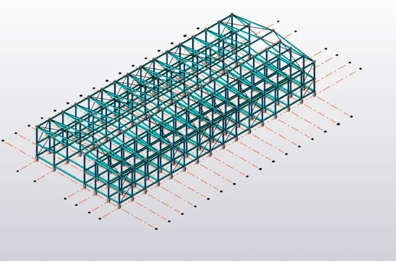
- Slab properties was designed using manage property sets option,in that select new followed by members and select slabs followed by general slab item and apply properties
- Now using the slab on beam option in model menu the slabs was applied on all floors
- Slab on Ground floor
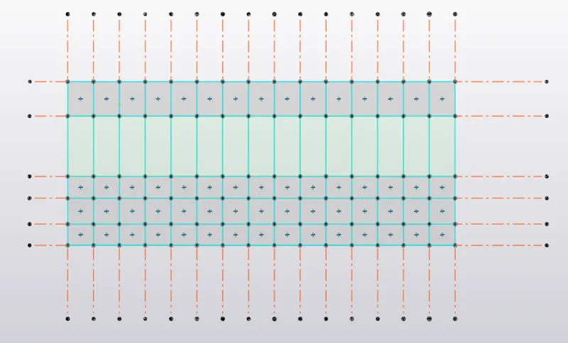
- Slab on First floor
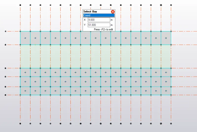
- Slab on Roof floor
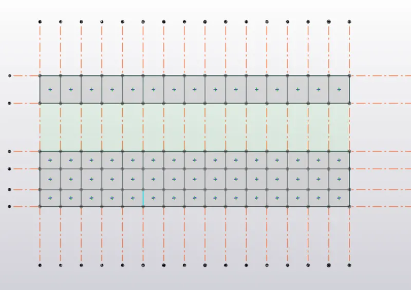
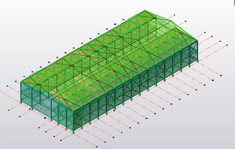
- Wall panel and Roof panel was applied using wall panel option and roof panel option from model menu
- 3D view of wall panel and Roof pane
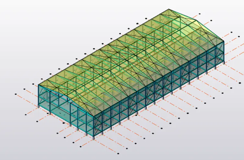
Load Calculations -
Initially based on IS 875 part 1, all the dead load in the steel structures were calculated as follows
1) Unit weight of concrete = 24
2) Finish load = 0.05*24 = 1.2
3) Brick wall loading = 0.15*20*5 = 15 kn/m
4) Brick wall loading = 0.15*20*7 = 21 kn/m
5) Brick wall loading (roof floor to roof top ) = 0.15*20*4.8 =14.4 kn/m
6) Roof loading on purlins = 1.5 kn/m
7) Ceiling loading = 0.3 kn/m
- On the load tab click on load cases option at the top left corner to open the loading dialogue box
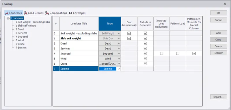
- In order to add new loading like imposed,wind,seismic and crane load .click on add option in loading dialogue box and add them and select type from the drop down list
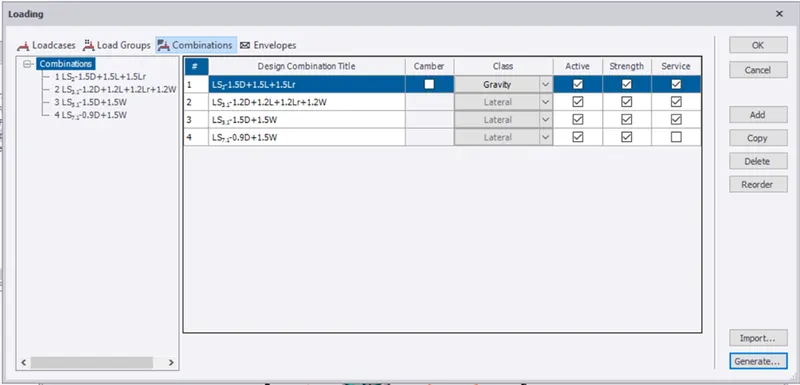
- For applying dead load first select dead load option from the drop down list at the bottom left side
- Open 2d view ground floor of the level within which you want to apply load
- In the loading list,select an appropriate load case
- In the Load tab,click on Area load
- In the property windows,adjust the load details according to need and click on that panel which you want to apply
- Load was applied in all floors and roofs
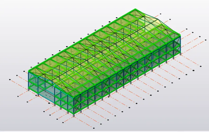
- For Roof load was applied as Full UDL
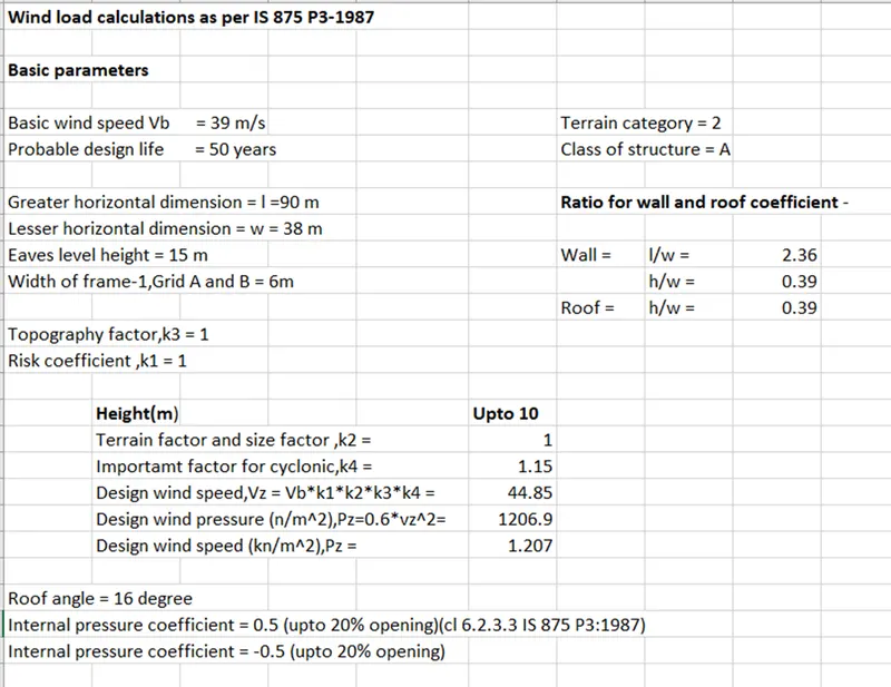
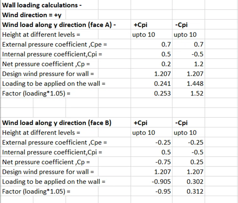
Wind Load Calculations -
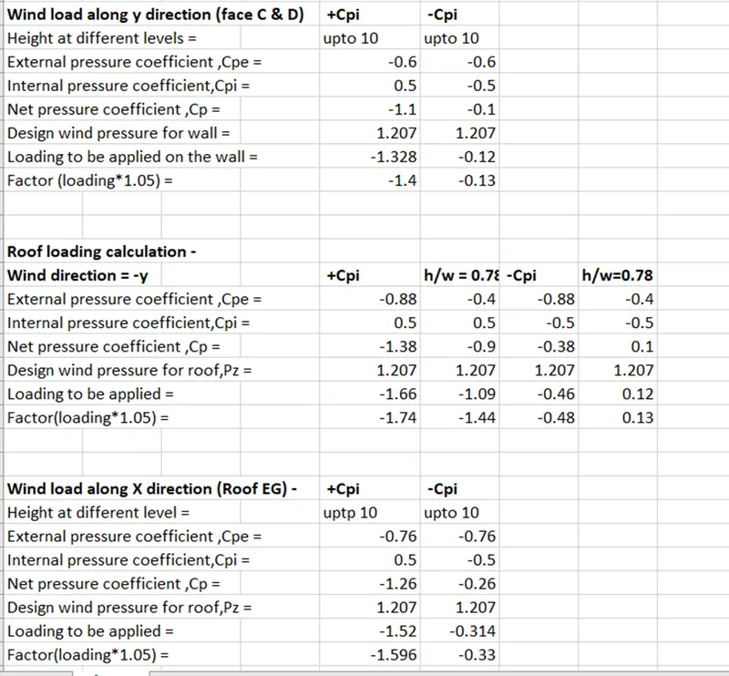
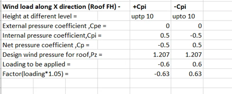
Crane Load Calculations -
Maximum concentrated load on crane = 100+35 =135 kn
Self-weight of crane will act as uniformly distributed load of intensity = 160/20 = 8 KN/M
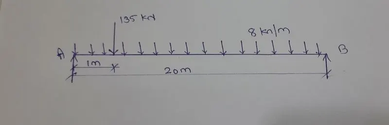
Taking moment about B-
Ra x 20-(135) x (20 x 10) =0
20Ra = 297000
Ra = 208.25 KN
Taking moment about A -
Rb x 20-(135)x(1-8)(20x10) = 0
20Rb = 189000
Rb = 86.75 KN
Ra+Rb = 100KN
The reaction from crane girder is distributed equally on two wheels at the end of the crane girder
Maximum wheel load on each of the crane wheel = 208.25/2 = 104.125 KN
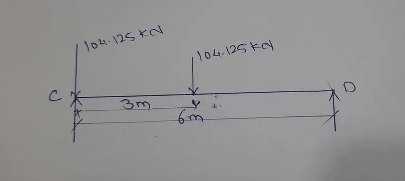
Maximum Bending Moment -
Assume self weight the the gantry girder as 1.5 KN/m
Total dead load = (self weight of rail+self weight of gantry girder) 0.3+1.5 = 1.8 KN/m
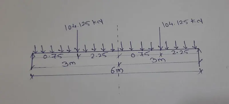
Taking Moment about D -
Rc x6 -104.125x(20.25+3)-104.125x2.25 =0
6Rc = 2655.187
Rc = 24655.187/6
Rc = 130.15 KN
Taking Moment about C -
Rd x6-104.125 x(0.75+3)-104.125 x0.75 =0
Rd x6 = 468.56
Rd = 468.56/6
Rd = 78.09 KN
Bending moment under wheel due to live load = Rd x2 = 78.09 x 2 = 156.18 KNm
Bending moment due to impact = 0.10 x 156.18 ( 10% increase due to MOT) = 15.618 KNm
Total bending moment due to live load and impact load = 156.18 + 15.618 = 171.798 KNm
Bending moment due to dead load = Wl *l/2 =1.8 x 6 x 6/2 = 8.1 KNm
Maximum bending moment = 171.798 + 8.1 = 179.89 KNm
Maximum Shear Force -
For maximum shear force
Rc x 6-104.125 x6-104.125 x3 = 0
Rc = 937.125/6
Rc = 156.18 KN
The maximum shear force due to wheel load = 156.18 KN
Lateral forces -
Lateral forces traverse to rails = 5% of the weight of crab and weight lifted
= 0.05 (135) = 6.75 KN
Lateral forces on each side of wheel F1 = 6.75/2 = 3.375 KN
Maximum horizontal reaction due to lateral force by proportion at C = Lateral force x reaction at c due to vertical load / Maximum wheel load due to vertical load
= 3.375 x (130.15/104.125) = 4.21 KN
At D -
=3.375 x (78.09/104.125) = 2.53 KN
4.21+2.54 = 6.74 kn
Bending moment due to lateral load by proportion = 3.375 x (15.18 / 104.125) = 5.06 KNm
- Now ceate new wind load with both +Cpi and -Cpi values using wind wizard option under load tab
- Also add seismic load at last
- Analyze the structrure and do necessary changes to correct the errors
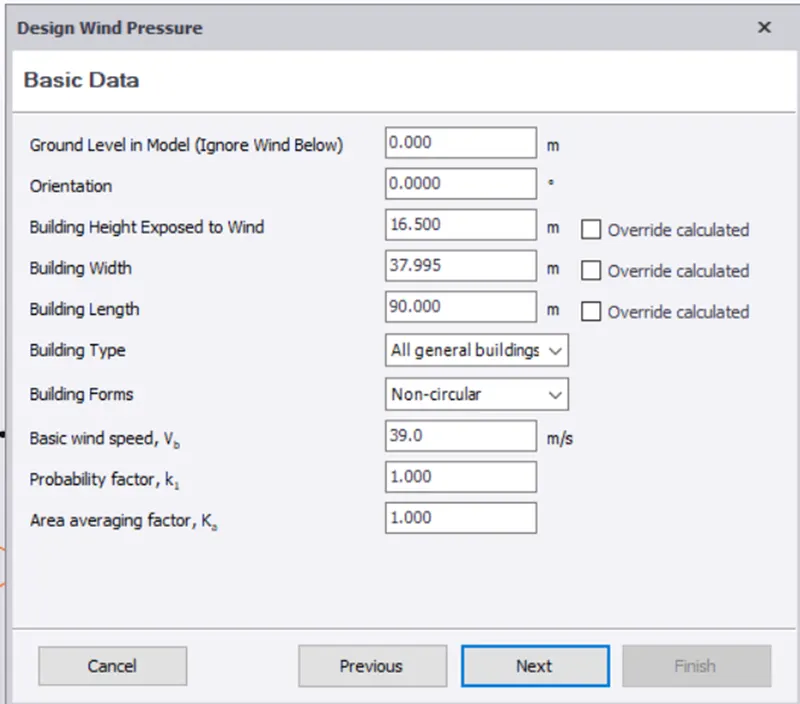
- Add basic wind pressure data
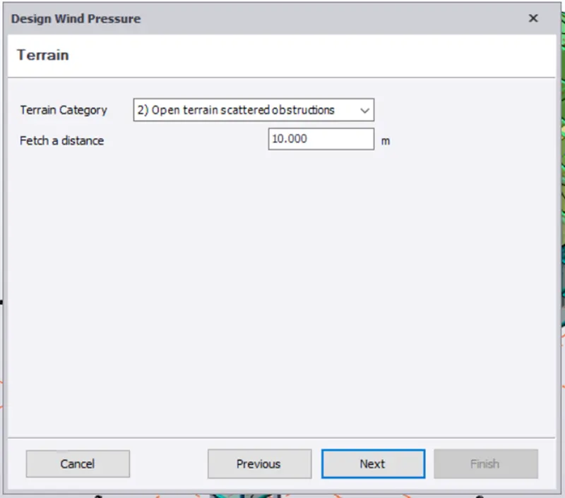
- Select terrain category as open terrain scattered obstructions
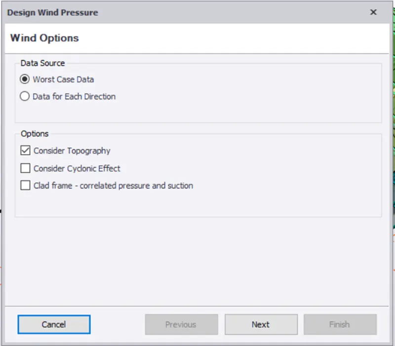
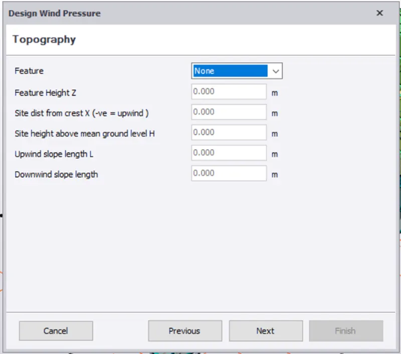
- Select topography for wind pressure
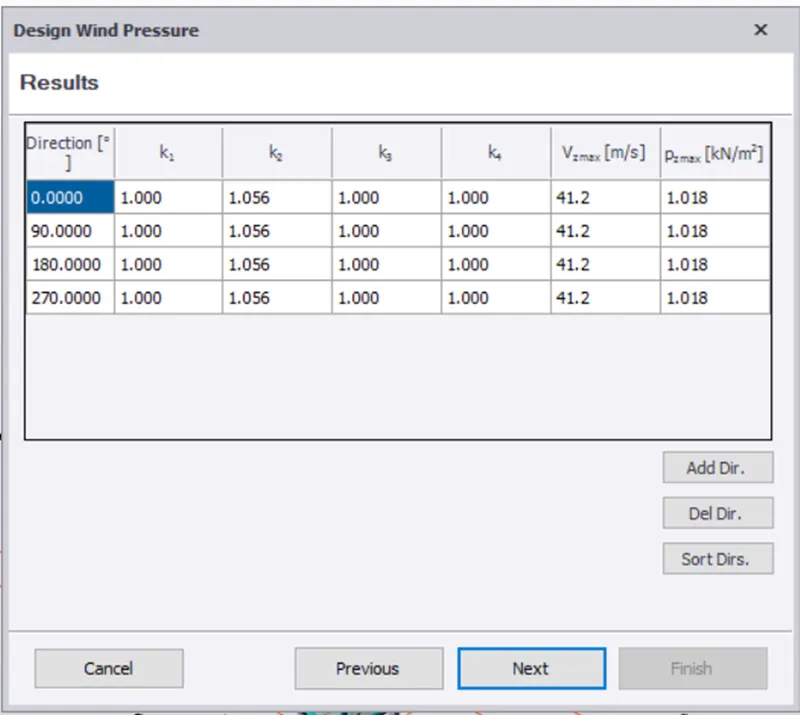
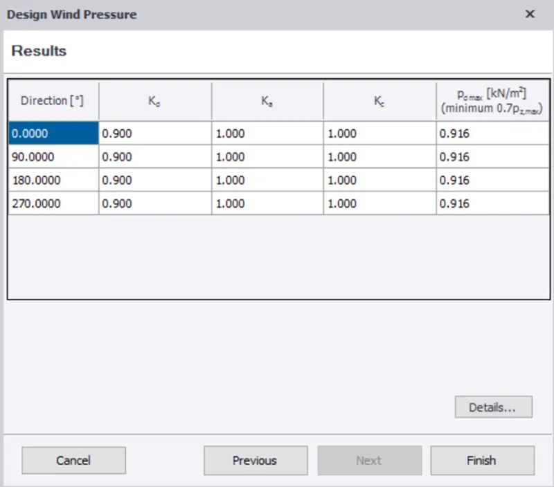
- Check the result value
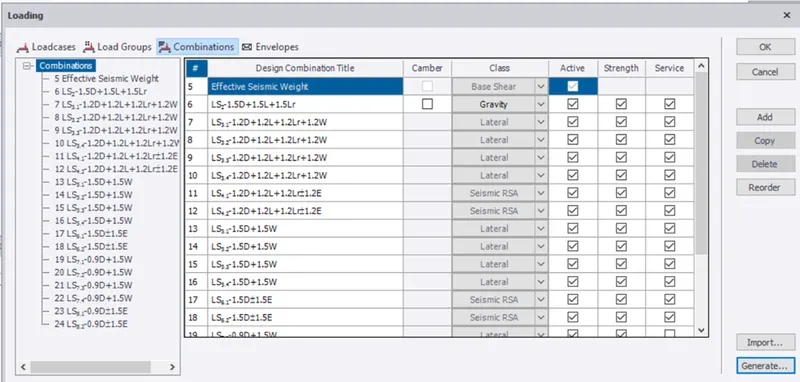
- Generate load combinations using generate option
Result -
1st order non linear analysis -