Project 1
Q. A portal frame has following details:
Portal beam having length of 4m and cross section of 300mm x 600mm (depth) and portal columns have height of 3m and cross section 300mm x 300mm.
1. The portal beam has two Bearing locations 1m from either end. The load from each bearing is 75 kN. Calculate the support reactions and displacement of each node.
2. Now change both the supports to fixed and compare the reactions and displacements with that of previous sub question.
3. Now provide 3 support conditions with 50 kN such that total load on the frame is same as that of Point 1. The bearings are 1m apart and 1st bearing is 1m from the end. Compare the reactions with that of sub question 2 and comment on the results.
4. Change the cross section of column to 300 x 400 mm such that 300mm width of column aligns with 300mm width of Portal beam. Rest all conditions remain same as that of sub question 2. Compare the portal beam and columns bending moment with that of sub question 2.
5. Now change the orientation of column such that 400mm size aligns with 300mm width of Portal beam. Compare the beam and column results with that of Sub question 4. Comment on the results.
Ans.
Aim and Introduction:-
- The aim of this challenge is to determine the forces, Bending moment and shear forces acting on strcture with different types of support and different load conditions using staad Pro.
- So first of all the model will be created in Staad pro. as per given in 1. with given loads is applied on the the structure.
- Then create as per different suppoert conditions with different orientation as given.Then the reactions, stresses and bending moments due to the loading is being analyzed for diffrent structures and comparing the results with each other.
Portal beam having length of 4m and cross section of 300mm x 600mm (depth) and portal columns have height of 3m and cross section 300mm x 300mm.
Staad Model
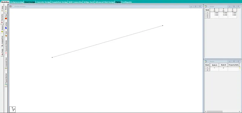
- The portal beam has been created as given as 4m.
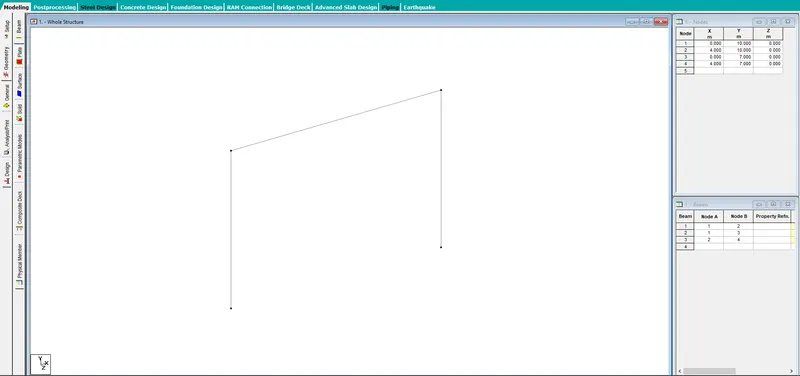
- The columns are also created as given.
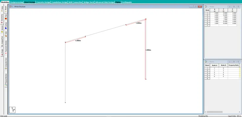
1. The portal beam has two Bearing locations 1m from either end. The load from each bearing is 75 kN. Calculate the support reactions and displacement of each node.
- Two bearing locations has been created.
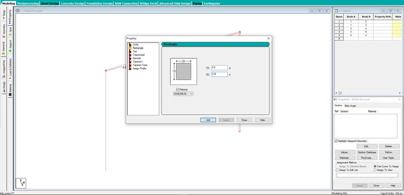
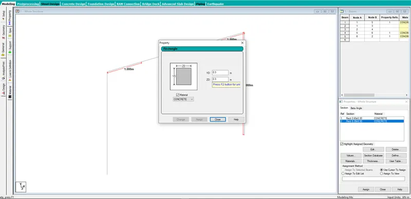
- Property for the beam defined and assigned to the beam.
- Property for the columns also has been defined and assigned to the columns of the struture.
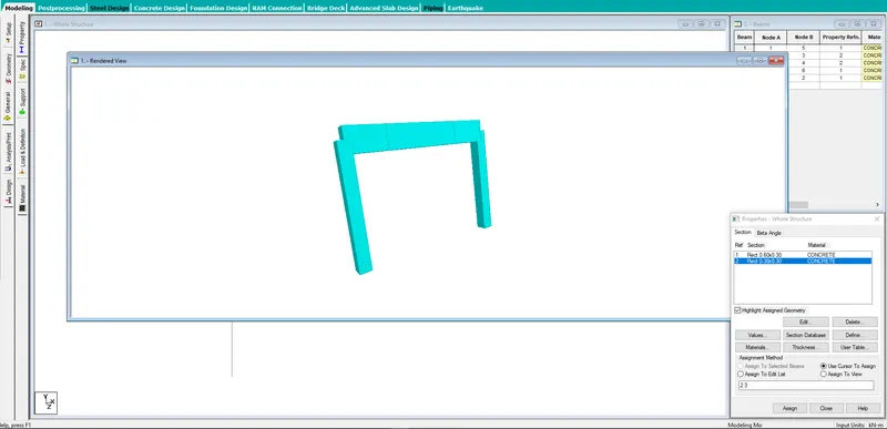
- The 3D view of the portal frame.
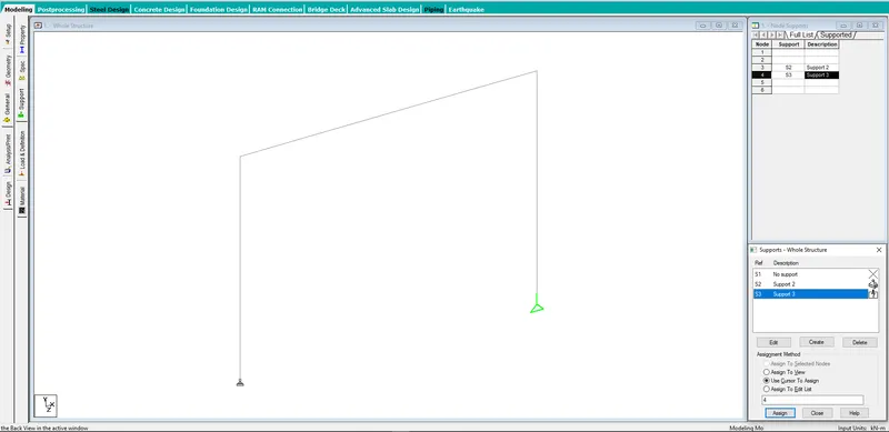
- Support Condition
- Pinned support and roller support has been defined and assigned to different nodes.
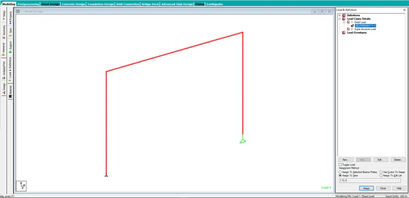
- Loads and Definations
- Dead load defined and has been assigned to the whole structure.
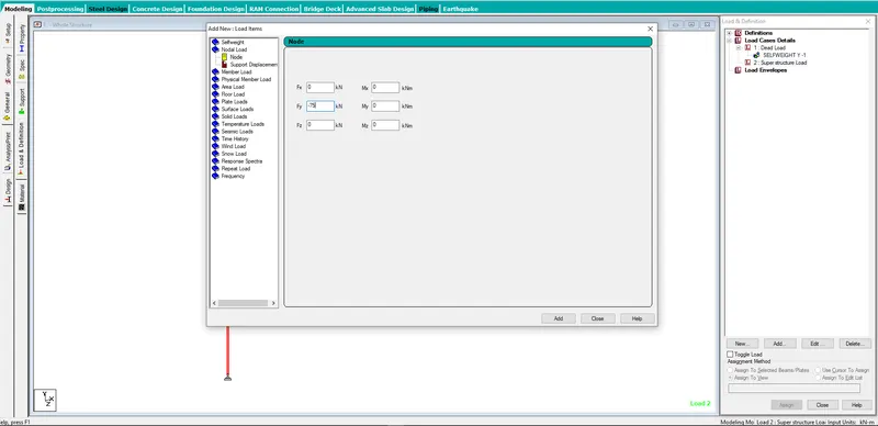
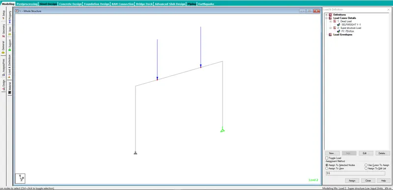
- Superstructure load as point load through the bearing has been define and applied to the structure.
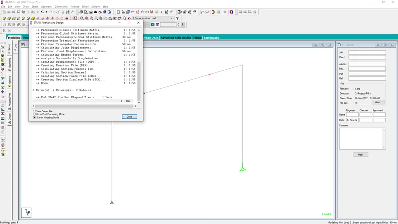
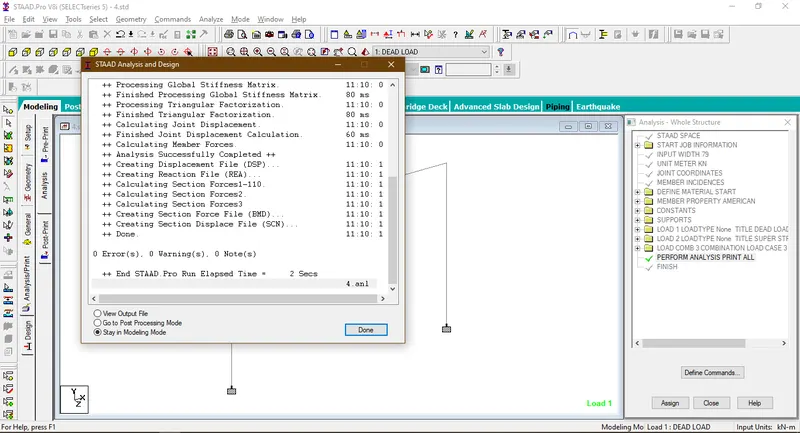
- The struture is being analyzed and the output gives the result as 0 error.
Result
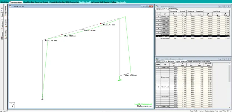
- Displacement
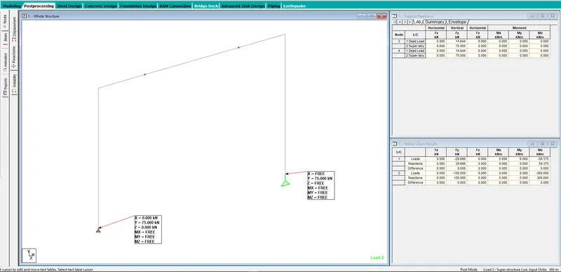
- Support Reaction
2. Now change both the supports to fixed and compare the reactions and displacements with that of previous sub question.
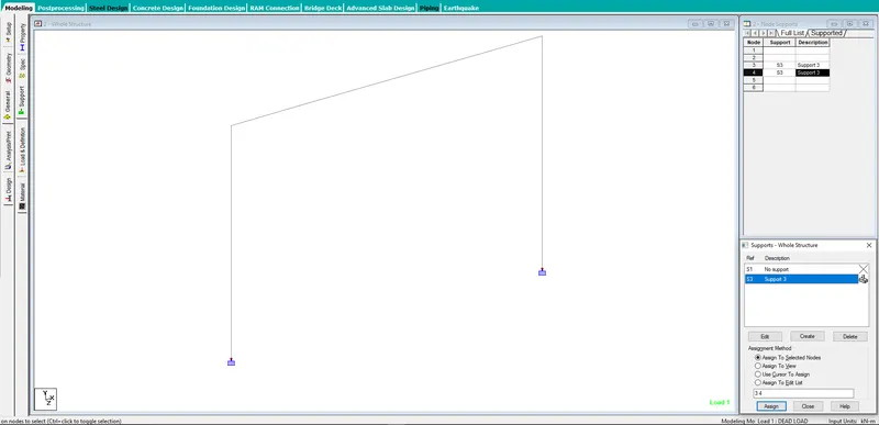
- In this case the support conditions has been changed to fixed support.
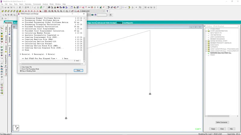
- The struture is being analyzed and the output gives the result as 0 error.
-
Result
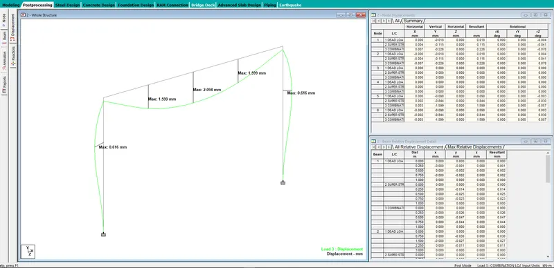
- Displacement
- For the maximum load case
- Support Reaction
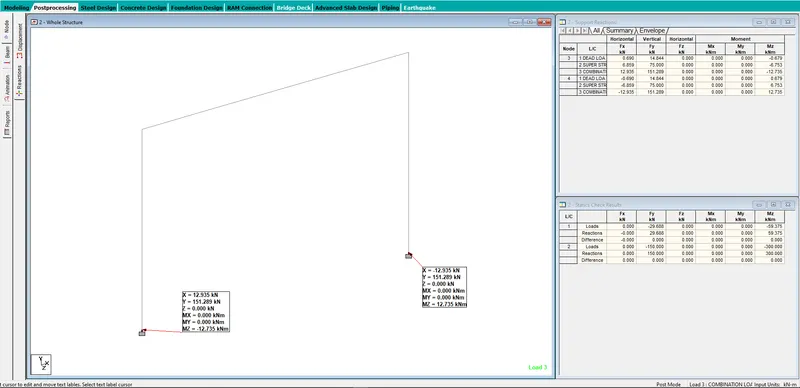
3. Now provide 3 support conditions with 50 kN such that total load on the frame is same as that of Point 1. The bearings are 1m apart and 1st bearing is 1m from the end. Compare the reactions with that of sub question 2 and comment on the results.
- Creating the third support node from the super struture in the mid section of the beam.
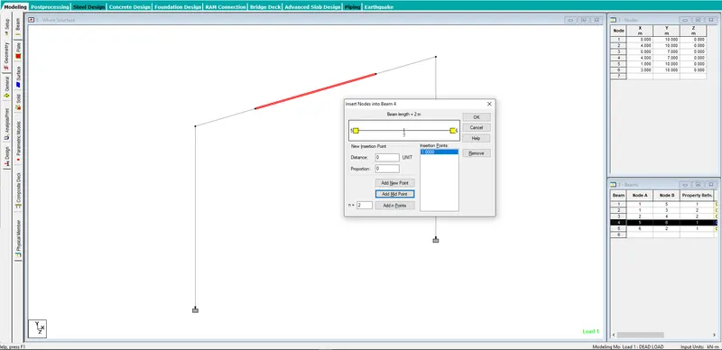
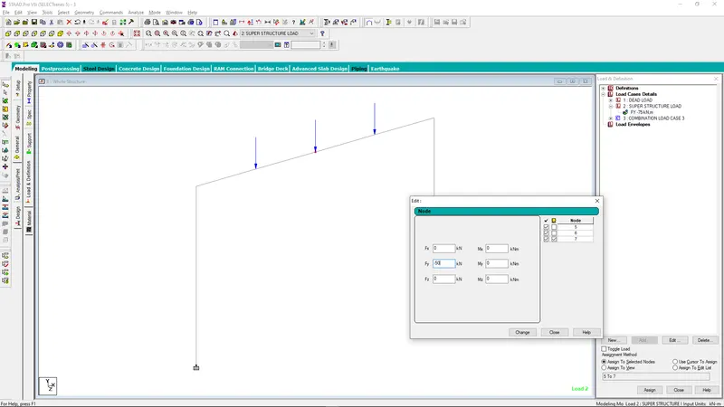
- 3 support conditions for bearing has been created and 50 KN has been applied to the struture.
- The struture is being analyzed and the output gives the result as 0 error.
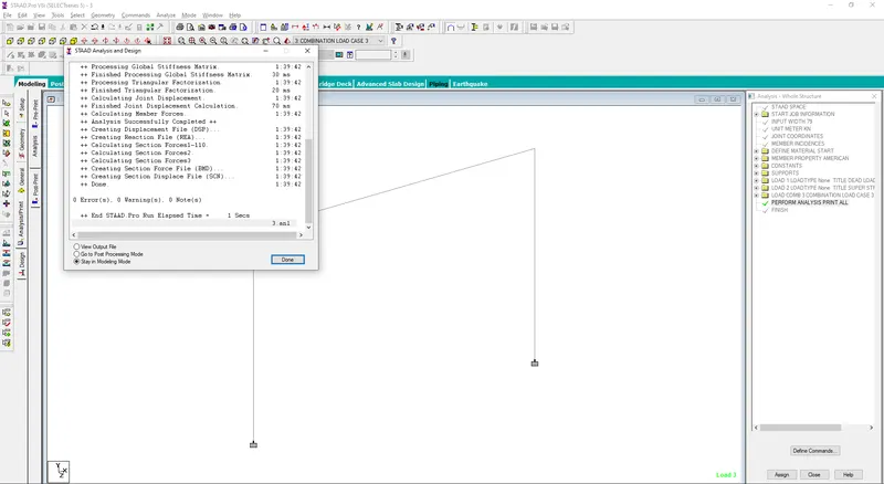
-
Result
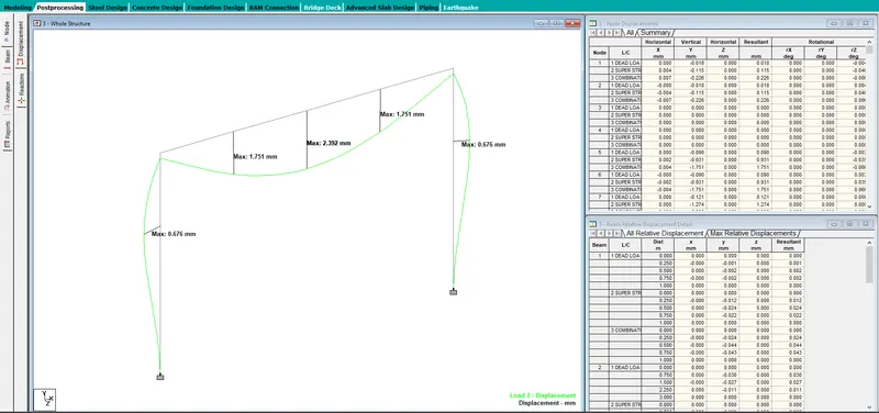
- Displacement
- For the maximum load case
- Support Reaction
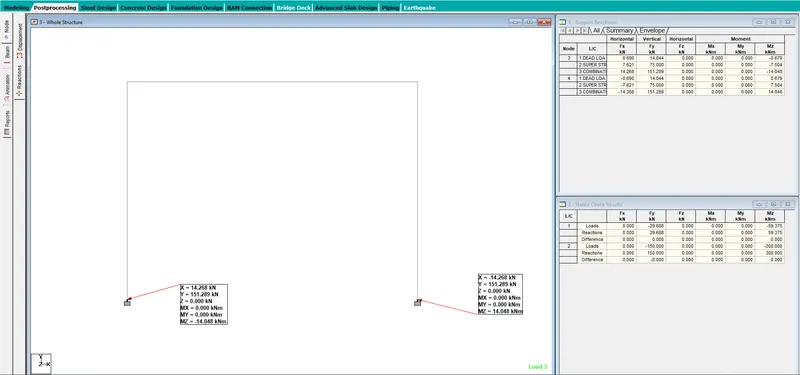
- In this case with comparing to the case 2 , the displacement in the mid point of the third case is higher.
- But as the super struture loading is symmetrical in both the case and the magnitude is same so the vertical reaction in both the cases is same.
4. Change the cross section of column to 300 x 400 mm such that 300mm width of column aligns with 300mm width of Portal beam. Rest all conditions remain same as that of sub question 2. Compare the portal beam and columns bending moment with that of sub question 2.
- The cross section of the column is to be changed to 300 x 400 mm in the model with reference to Sub question 2.
- The property in model is to be changed.
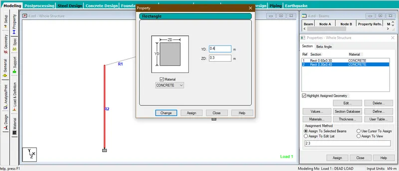
- The 3D view of the struture with alligning the 300mm width of column section to the 300mm of the beam section.
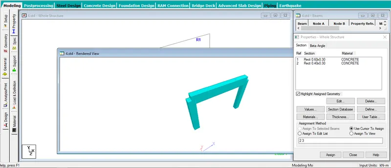
- All other sections,loadings & support conditions remain same.
- The struture is being analyzed and the output gives the result as 0 error.
Result and Comparision
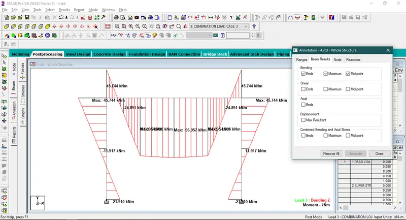
- The bending moment diagram with maximum magnitude and magnitude at mid point and ends.for the model created in sub question no.4.
- The bending moment diagram with maximum magnitude and magnitude at mid point and ends.for the model created in sub question no.2.
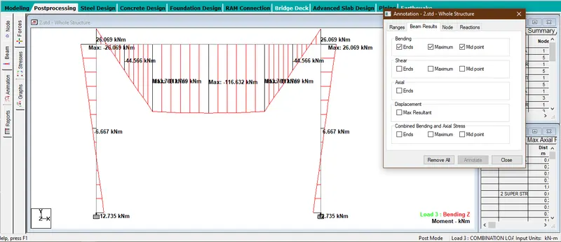
From the above two results this can be concluded that the bending moment at the mid section of the beam is more in the 2nd case than the 4th case.
The bending moment in the mid sectionof the beam is lesser in the 4th case but end moments is higher in the 4th case as the section in the ends is increased.
5. Now change the orientation of column such that 400mm size aligns with 300mm width of Portal beam. Compare the beam and column results with that of Sub question 4. Comment on the results.
- The cross section of the column is to be changed to 400 x 300 mm from 300 x 400mm in the model with reference to Sub question 4.
- The property in model is to be changed.
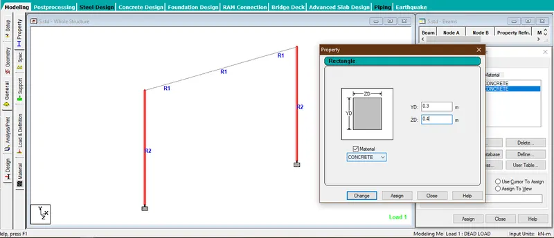
- The 3D view of the struture with alligning the 400mm width of column section to the 300mm of the beam section.
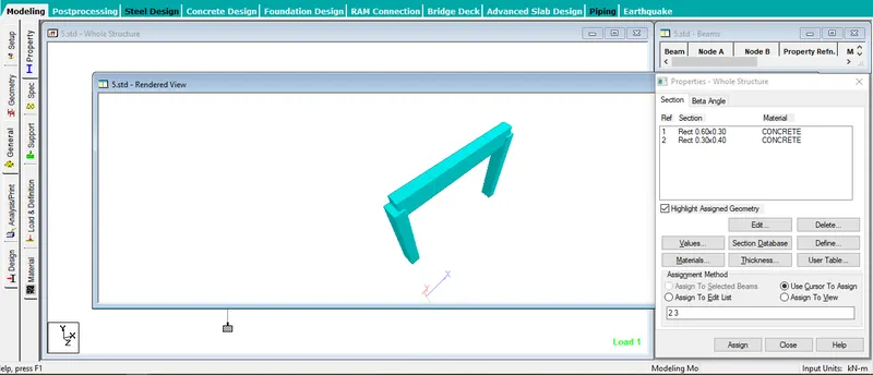
- All other sections,loadings & support conditions remain same.
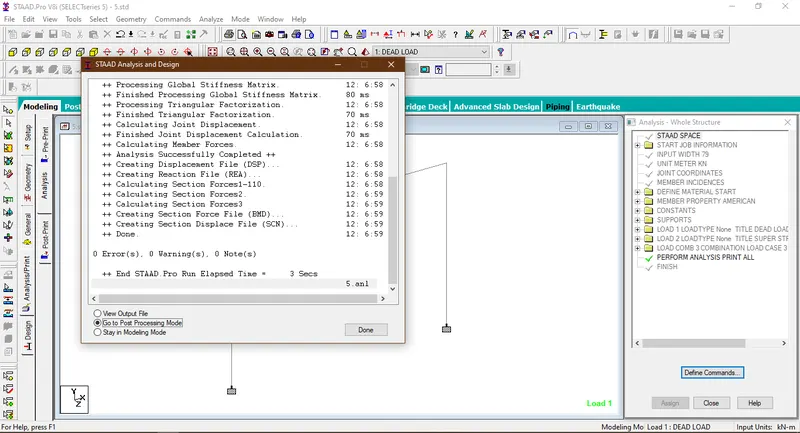
- The struture is being analyzed and the output gives the result as 0 error.
Result and Comparision
- The bending moment diagram with maximum magnitude and magnitude at mid point and ends.for the model created in sub question no.4.
- The bending moment diagram with maximum magnitude and magnitude at mid point and ends.for the model created in sub question no.5.
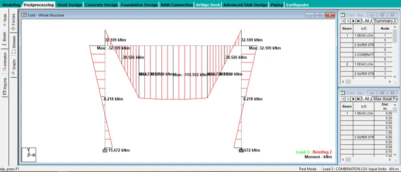
- The benging moment in the mid section of the beam is higher and the BM in end section is lesser than the sub question no. 4 in sub question no.5. Because the section modulus in the respective 400mm dimension direction is higher than the otheer direction.
- Shear Force
- The shear force with maximum magnitude and magnitude at ends.for the model created in sub question no.4.
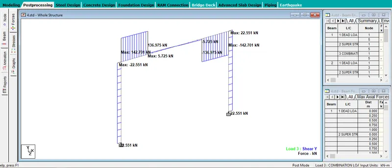
- The shear force with maximum magnitude and magnitude at ends.for the model created in sub question no.5.
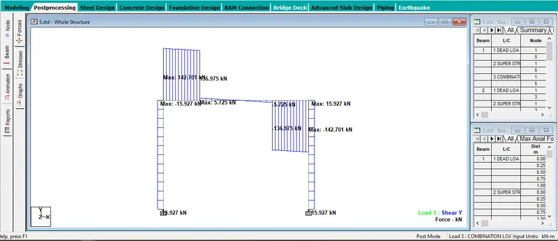
In this comparision both the results for the shear force is identical.
Axial Force
- The axial force for the model created in sub question no.4.
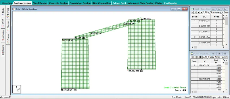
- The axial force for the model created in sub question no.5.
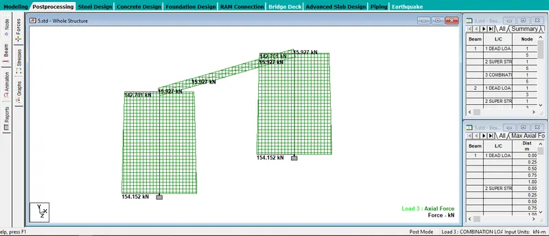
In this comparision both the results for the axial force is also identical in both the cases.