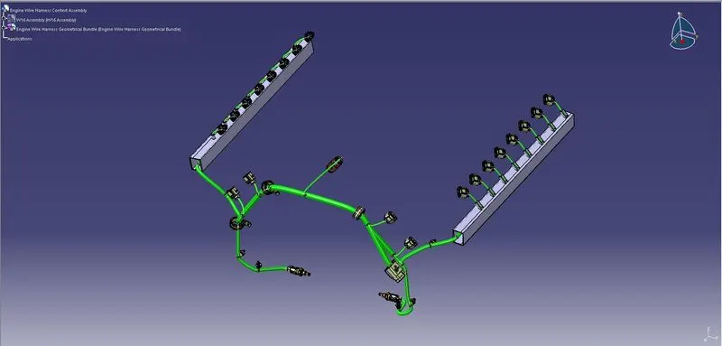
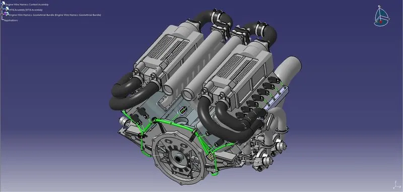
Project 1
Challenge: Route the Wiring harness on Given Engine and Prepare flatten view drawing in CATIA V5
Aim: The Aim of the project is to route the wiring harness for the give engine and create flattening view of same by considering the harnessing rules and industry best practices like maintaining proper clearence between sharp edges and proper saftey measures given near high thermal zones
STEP1: Get the engine data
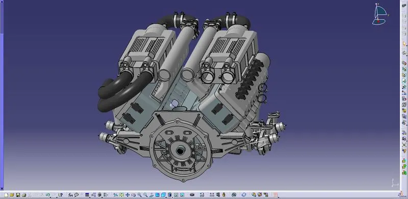
Given Engine: Buggati W16 Engine
Rules to maintain during wiring harness
1.Provide Proper slack if possible to avoid tension buildup in connector connection crimping region
2.,Maintain a proper clearence between edges to avoid chaffing to the branch.
3.Avoid routing over bolts and threaded studs
4.Branch length should be minimum 50mm
5.Distance between two branch points should be 50mm
6.Use proper guide channel near thermal zones to protect harness
7.Harness should be easy to assemble and manufacture
Step2: Identify and collect the required connector components
The given Engine has
1-16 injector sensors 8 sensors each side - 4 pole connector needed
2-2 chamshaft sensors each side - 4 pole connector needed
3-oil pressure sensors 1 each side - 2 pole connector needed
4-oil temperature sensor - 2 pole connector needed
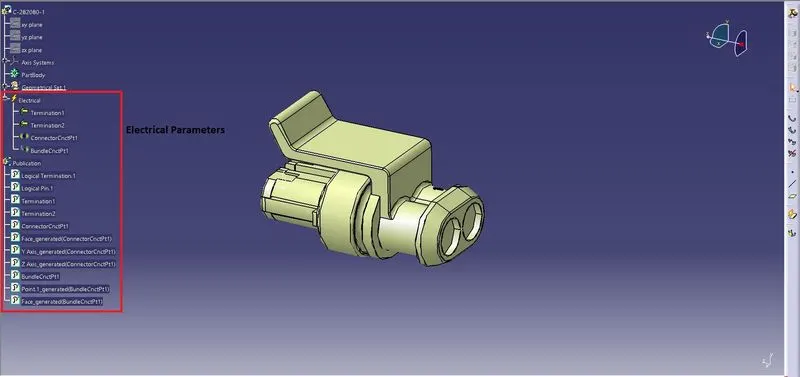
4-Pole connector
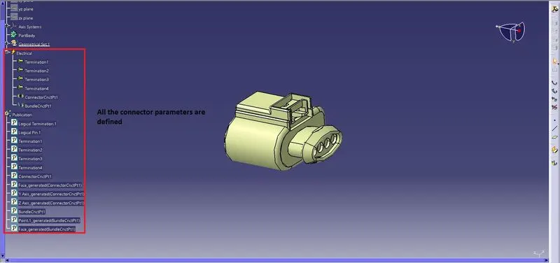
2 Pole connector
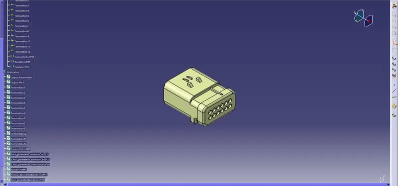
Interconnector 12-pin connector to establish connection between Engine harness and vehicle harness
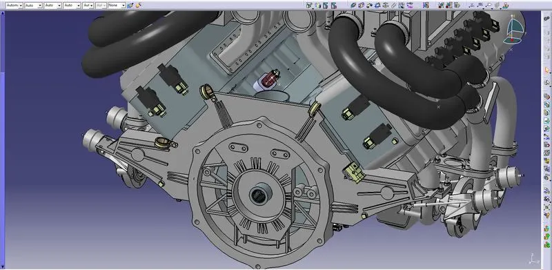
Step 3:- Start Positioning Connectors to the respective sensors
Connect 4-pole connector to Injector Sensor
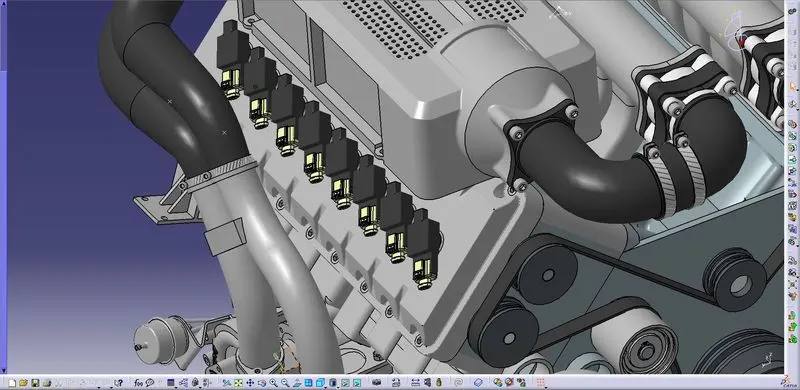
Connect 4-pole connector to camshaft sensors
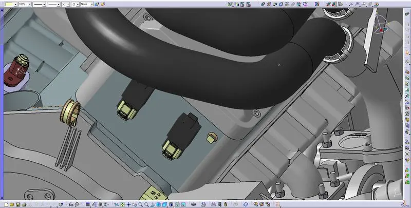
Connect 2-Pole connector ro oil pressure sensor
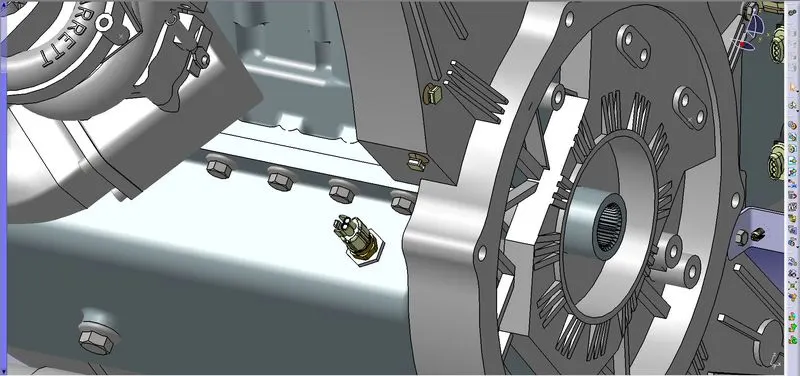
Connect 2-pole connector to oli temp sensor
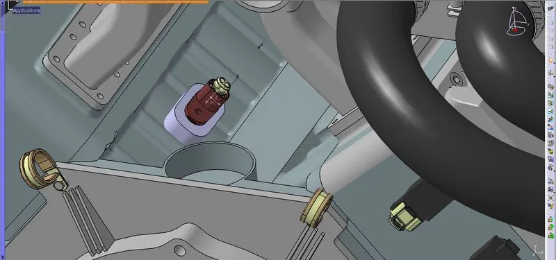
Once all the connectors are placed check for INTERCONNECTOR to connect engine harness and vehicle harness
Decide which side Main vehicle harness located and place the Interconnector so that there will not be more slcak between Engine harness and vehicle harness so that branch wont be affected by engine rocking
Decide how the interconnector is to b placed on to engine so that it wont be affected by Engine(Choose a safe place to Interconnector)
In this project the interconnector is placed at right side of engine which is closer to vehicle harness
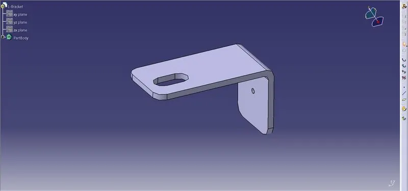
A L-Bracket is created to hold the Interconnector and is placed on one of the bolt on the engine
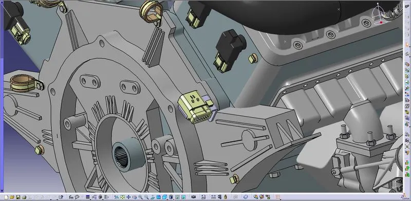
Once all the connectors are placed decide how to route the branches by considering the rules and saftey measures
use clamps and clips at appropriate locations to route the bundles
Step:4
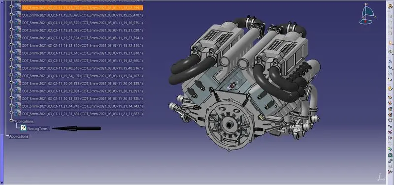
Once all the connectors and clips clamps are placed Define the assembly as Elctrical in Electrical Harness Assembly using Geometrical Bundle Command
Activate the command and click on geometric bundle product file
Step:5- Start Routing
Make sure Geometrical bundle product file iss activated and click on Multi Branchable document and start routing by selecting appropriate connectors and clips
Input required dia of bundle slack if required
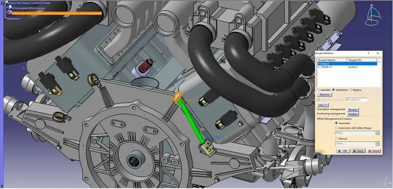
Similarly route the branches between remaining clips and connectors
Use Add Branchpoint command to add point onto a branch to route sub branches
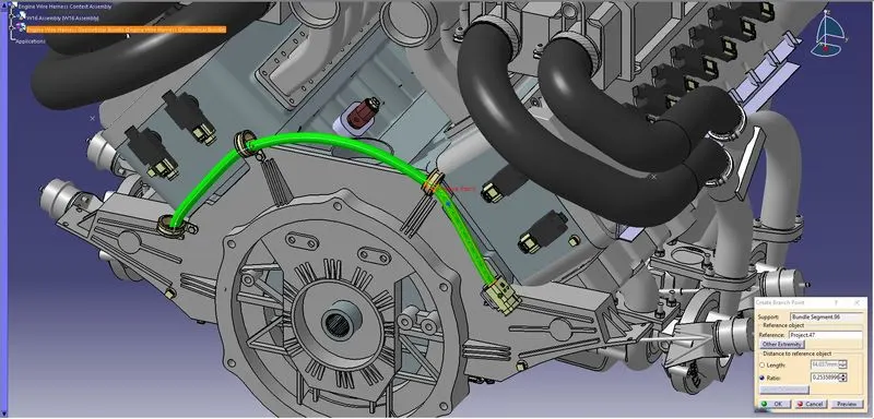
Guiding channel must be used near exhaust or near high heat zones
A guiding channel is created to route the bundle segment from main branch
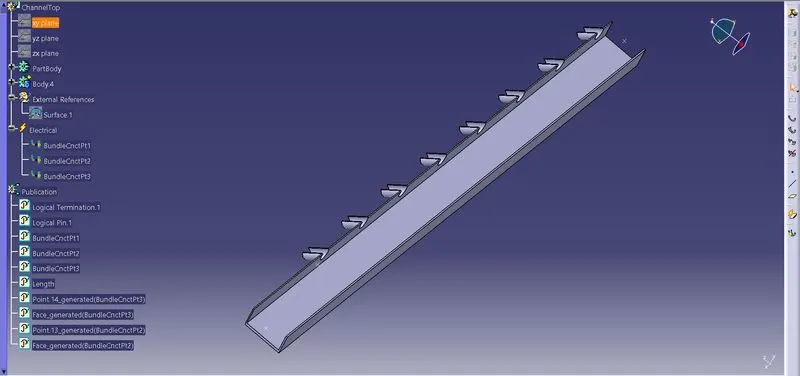
Place the guide channel at appropriate place without touching any surrounding engine parts
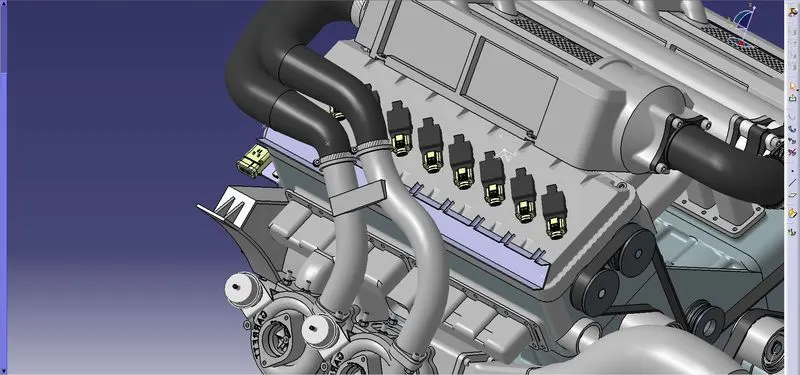
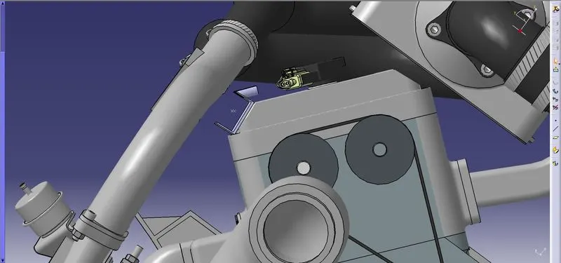
Ensure proper clearence
Create a external curve in guide channel to create bundle segment
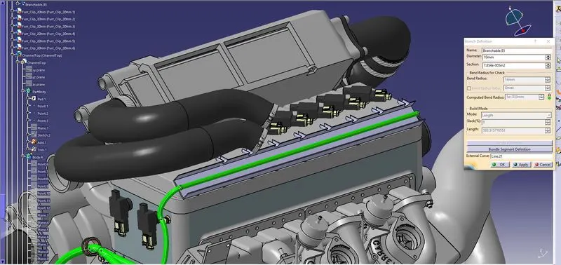
use External curve option in Branch definition menu to route using external curve
To create routing to the injector connectors from external branch create circular openings and define bundle entry point or create external sketch and route through it
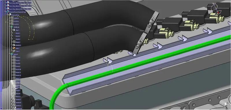
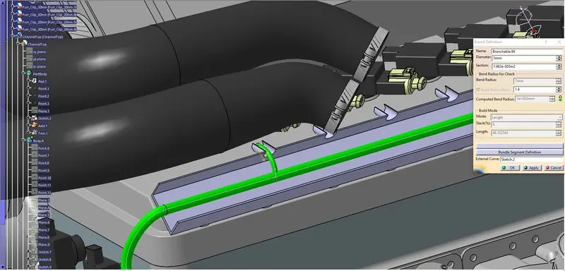
Then use the external routed sub branch to route the injector sensor connector
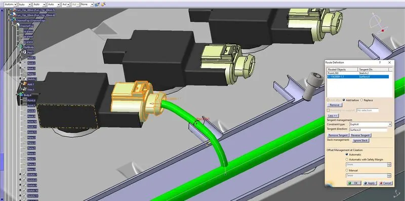
Finally route the branch to all conectors