Project-1_WIRING HARNESS ROUTING FOR ENGINE
Wiring Harness Routing On Engine
Engine:
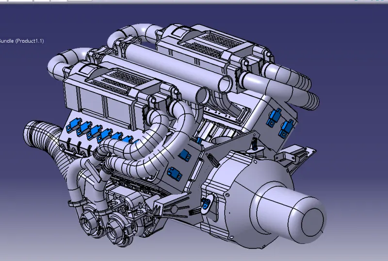
Steps involved;
- First of all downloaded all the CAD files needed from the respective sites and saved the CATpart files.
- Given the electrical definition for all the connectors, clips, clamps, channels and for the left needed to be defined for the bundle routing.
- Created the catalogue document file for different categories.
- Added all the equipments to the respective catalogue files.
- Created a new product file and named Engine Harness context.
- Added the engine to the engine harness context product file.
- Added a new product file to the engine harness context.
- Named the new product file as "Assm_Geometrical_Harness_Bundle_Engine", Required connectors(Electricaly defined) are added to the new product file (Assm_Geometrical_Harness_Bundle_Engine).
- Placed all the connectors to their connection points using manipulation and compass tool.
- Also channels are added as required and placed to the convenient position shown in figure below.
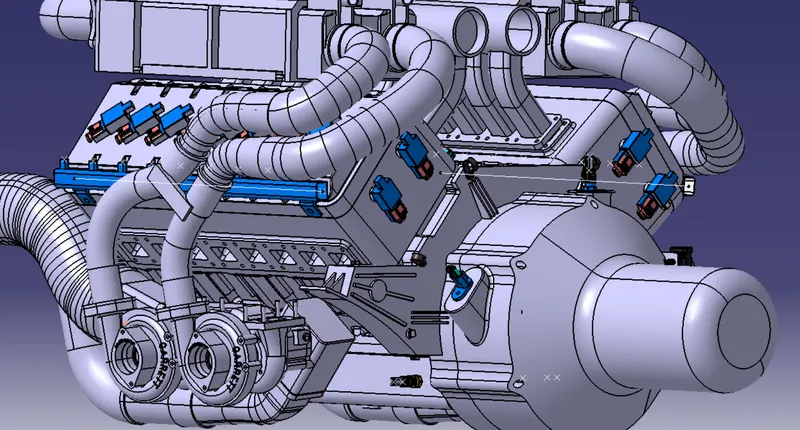
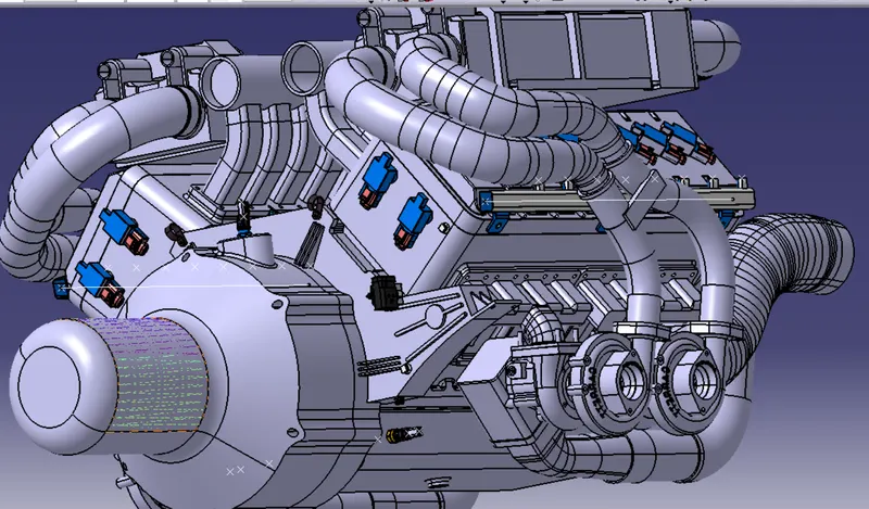
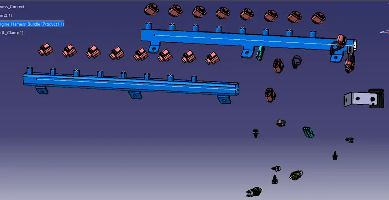
- Required Clamps and Clips are added to the assembly for mounting the wires and connectors conveniently.
- Then first electrically defined the geometrical harness bundle file.
- On clicking multi-branchcble-document command a new part file named 'multi-branchable' is added to the "Assm_geometrical_Harness_bundle_engine".
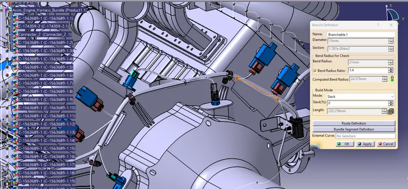
- Then started routing using branch definition.
- Required slack length and bend radii are provide for the wiring harness routing.
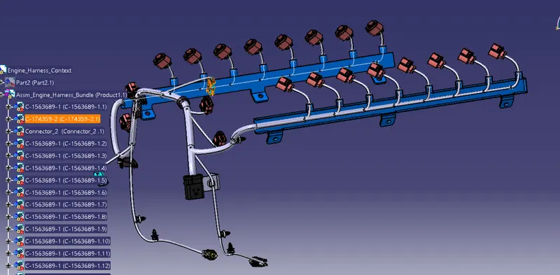
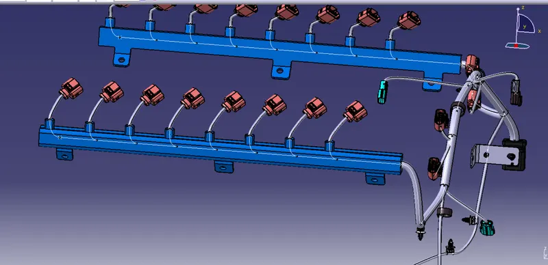
- Now the routing is almost done.
- Now we have to provide the protective covering for the wires. Insulation tapes and corrugated tubes can be used.
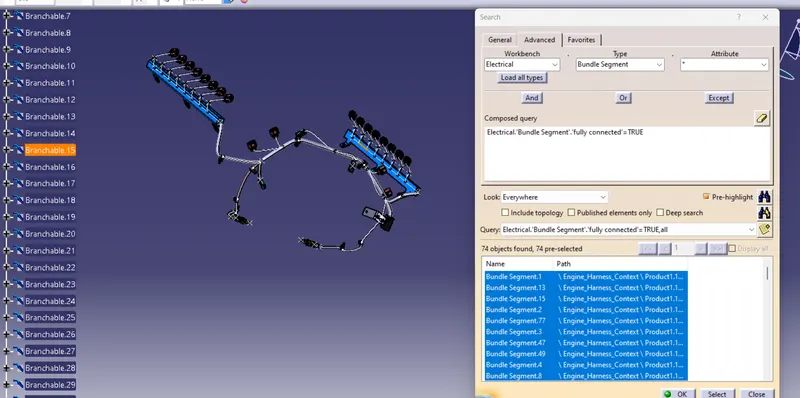
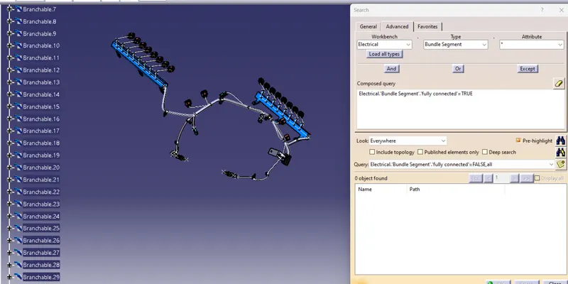
- Before that checking wether the bundle segments are fully connected or not. Below figure shown the Bundle status.
- Figure below showing adding the protective covering to the bundles.
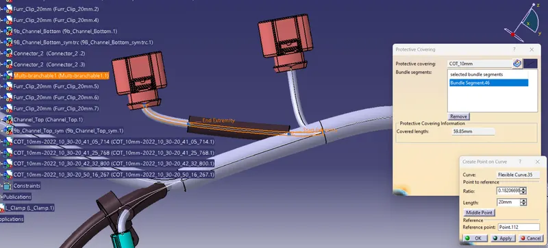
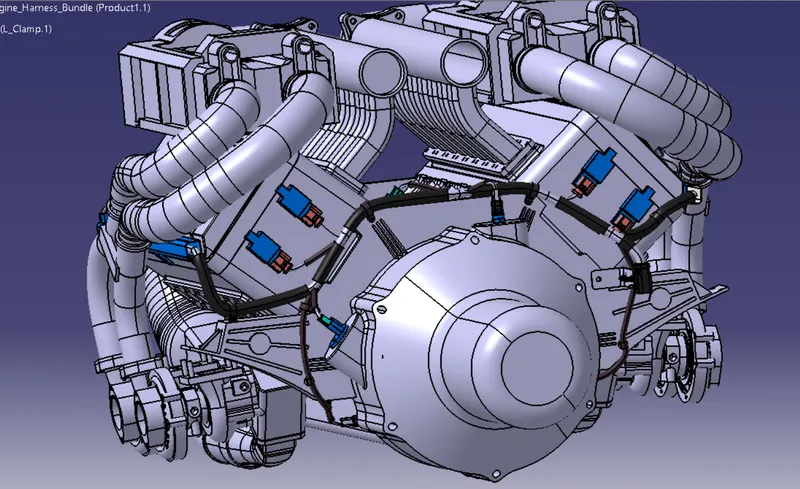
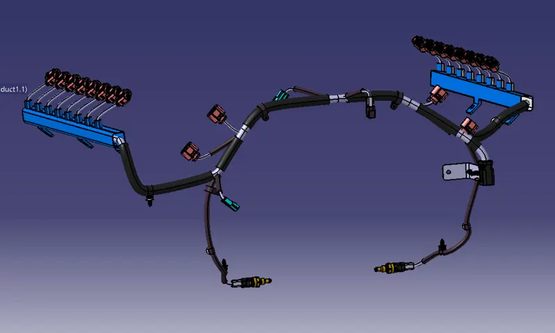
figure after adding all the needful protective covering;
Flattening and Drawing Creation
- New product file is opened for the flattening.
- jump to electrical flattening work bench and set the Harness Flattening parameters.
- Then click on the Flatten command and select the bundle to flatten.
- Select all branches and set the reference face or plane to flatten respectively.
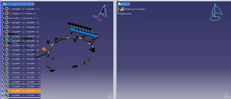
After Flattened and adjusting the bundles aligned using rotate and roll commands
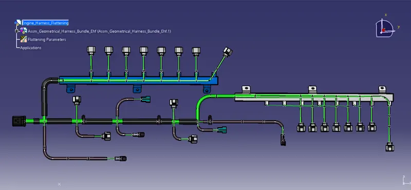
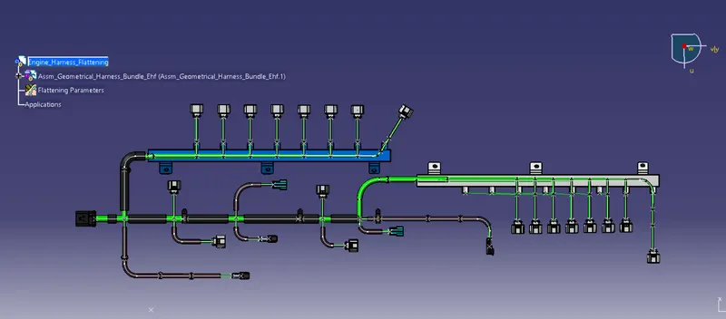
Drawing Creation:
- Created new drawing file
- Created the drawing using front view command and selecting the face that used to flatten the routing
- View properties are setted.
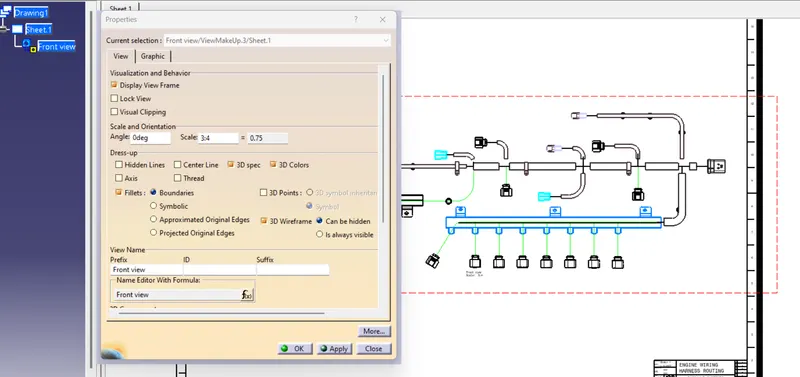
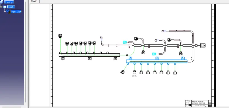
Saved the drawing file.
All the files are atteched.