Project 1
Project:
Develop a double-acting actuator model using Simscape Multibody and Simscape components. The mechanical system of the cylinder needs to be built using Simscape Multibody library components / blocks, and the hydraulic system needs to be modelled using Simscape library physical components.
Double-acting hydraulic cylinders have a Cylindrical housing and one piston. When hydraulic oil is supplied to its cap end port, hydraulic pressure force will be applied over the piston and the end cylinder will be extended. During the extension of the piston hydraulic oil at the rod, the end side will be pushed out and directed towards the reservoir.
For the returning stroke, the hydraulic direction is reversed with the help of the direction control valve. During the returning stroke hydraulic oil is supplied to the rod end side and hence piston is retracted. During the retracting of the piston cap end, oil is directed towards the reservoir. hence the double-acting hydraulic actuator operated in both the directions.
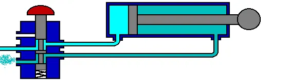
Construction of Model:
a) Electrical Sysytem:
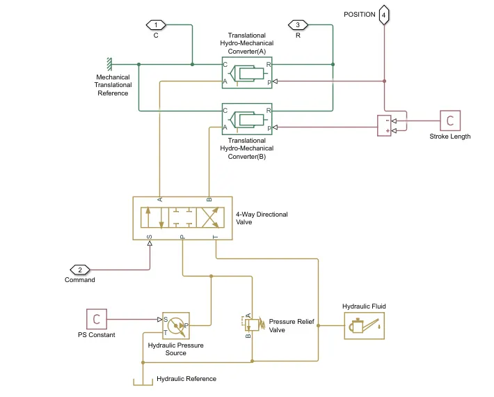
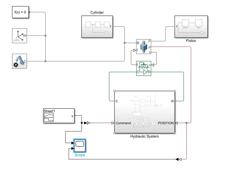
- In chamber A, a tension at port A maneuvers the cylinder from 0 to stroke length. The dislodging of the cylinder equivalents to the position result of the Prismatic Joint block. To show chamber A:
- Associate the ports C and R of the Translational Multibody Interface block to the ports C and R of the upper Translational Mechanical Converter (IL) block, individually.
- In the Translational Mechanical Converter (IL) block, set Interface removal to Provide input signal from Multibody joint to empower port p.
- Interface ports p of the Prismatic Joint block and Translational Mechanical Converter (IL) block.
- In chamber B, the strain at port A maneuvers the cylinder from 0 to negative stroke length. Subsequently, you really want to change the default direction and add an offset to the information position sign of the lower Translational Mechanical Converter (IL) block. The offset approaches - dB.
- In the lower Translational Mechanical Converter (IL) block, set Mechanical direction to Pressure at A makes negative dislodging of R relative C.
- Set Interface uprooting to Provide input signal from Multibody joint to empower the port p.
- Add a PS Constant block and indicate the steady as the stroke length of the chamber.
- Add a PS Subtract block, then associate it to the PS Constant and Prismatic Joint blocks as displayed in the graph. Note that the result of the PS Subtract block rises to - dB.
- To restrict the movement of the cylinder:
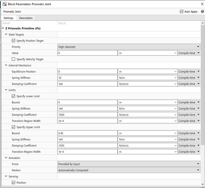
- In the Prismatic Joint block, under the Limits segment, select the Specify Lower Limit and Specify Upper Limit boundaries.
- Under the Specify Lower Limit area, the Bound boundary shows the base distance between the edges B and F of the joint block. In this model, determine the Bound boundary as 0 m.
- Under Specify Upper Limit, the Bound boundary shows the greatest distance between outlines B and F of the Prismatic Joint block. In this model, determine the Bound boundary as the stroke length of the chamber.
Electrical System
b) Mechanical Multibody System:
1) Cylindrical Assembly:
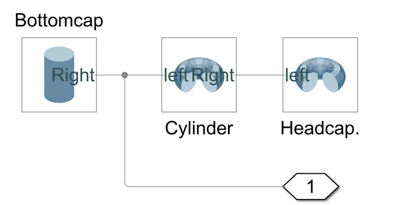
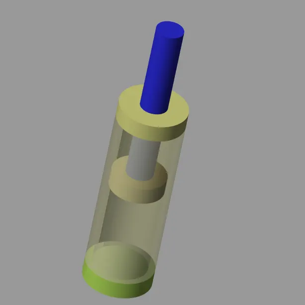
The Assembly Consist of Barrel, Head cap and Bottom cap.
Barrel is the part where the piston slide upside down and also fuel Container.
Head cap is used to Protect the Cylinder top side from Leakage and used as a closure.
Bottom Cap is used as Protect the Cylinder Bottom side from Leakage and used as a closure and also Allow the Piston rod to Slide along it.
Cylindrical Assembly
2) Piston Assembly:
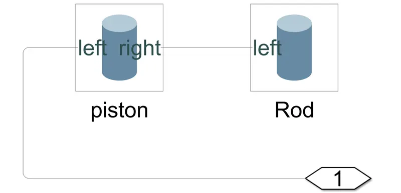
The inlet or outlet flow inside the barrel pushes the Piston or Plunger of hydraulic cylinders. When the Piston moves to either side of the cylinder, the Rod contracts or expands.
These are the parts of the basic hydraulic cylinders. More types of cylinders are more complex in their construction. However, these components are essential to almost all hydraulic cylinders, and it is good to know what they are and how they work.
Piston Assembly
3) Prismatic Joint:
A prismatic joint is often called a slider — for example, a “crank-slider linkage.” This is a type of kinematic pair and an idealized way to describe how motions are constrained within machines.
There are several physical embodiments of a prismatic joint, such as slideways. Rectangular cross-sections may be used in combination with plain or rolling bearings to enable linear motion while preventing rotation about the axis of movement.
Hydraulic and pneumatic cylinders are typically modeled as prismatic joints although they may also permit rotation about their axis. Kinematic pairs are classified as higher pairs and lower pairs. Higher pairs involve point or line contact, such as a ball or roller that’s rolling over a surface. Lower pairs can be visualized as surface contact.
Prismatic Joint
Overall Model:
Resultant Graph:
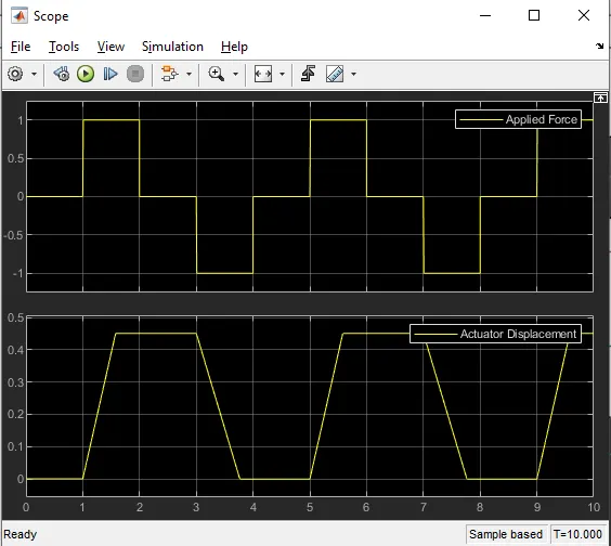
This Resultant graph Shown the force applied vs Actuator Displacement
3d actuator Model:
Conclusion:
Thus,Double-Acting Actuator model using Simscape Multibody and Simscape components.