Project 1
OBJECTIVES
Design a battery pack for a car roughly 150 Kw with 120 V. Use 3500 mAh 3.6V nominal NMC chemistry cell.
- Design the battery pack configuration.
- Draw the BMS topology for this battery pack.
ANSWERS
Design a battery pack for a car roughly 150 Kw with 120 V. Use 3500 mAh 3.6V nominal NMC chemistry cell.
- Design the battery pack configuration.
Aim:
To design the battery pack with the capacity 150Kw 120V by using 3500mAh 3.6V. And BMS topology for the battry pack
Calculation:
To design the battery pack we need cells which are connected in series and parallel to meet the requirment. The required condition - 220v and 50Ah.
Let us concider the cells with
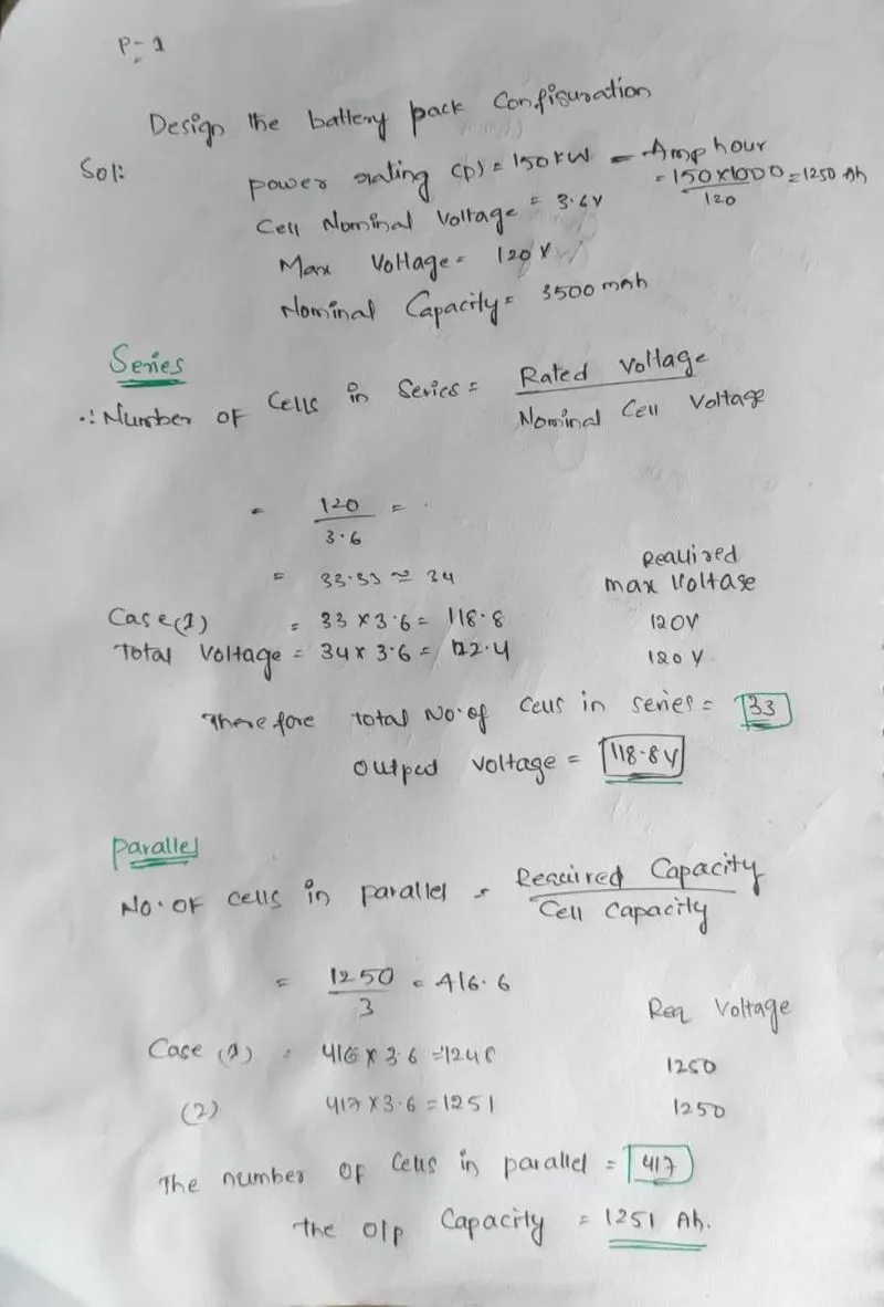
Nominal voltage = 3.6v
Capacity = 3000mAh = 3Ah
To meet the requirment of 120v and 150Kw, we need to find the number of cells connected in series and parallel.
First convert the battery capacity 150Kw to Ah
Amper hour = Watt hour / Voltage
Amper hour = 150*1000 / 120 = 1,250 Ah
Series:
Number of cells in series = required voltage / Nominal voltage of the cell
Number of cells in series = 120/3.6 = 33.33
We have to round off to lower value and higher value
Case-1) Number of cells in series = 33
Case-2) Number of cells in series = 34
Total volatge = nominal votage of cell * number of cells in series
| Number of cells in series | total voltage | Requred voltage | |
| Case - 1 | 33 | 33*3.6 = 118.8 | 120 |
| Case - 2 | 34 | 34*3.6 = 122.4 | 120 |
The condition to choose the number of cells are
Nomial voltage of battery should not excide the Load volatge
Max Volatge of battery should be less than the Load Max Volatge
Min Volatge of battery should be greater than the Load min Voltage
We have to round off to lower value so that it will not excide the required value
There fore Number of cells in series = 33
Output total volatge will be 118.8V
The output voltage can be adjusted to 120v by a Buckboost converter to meet the requirment of 120v
Parallel:
Number of cells in parallel = required capacity / cell capacity
Number of cells in parallel = 1,250 / 3 = 416.6
We have to round off to lower value and higher value
Case-1) Round off to lower value = Number of cells in series = 416
Case-2) Round off to higher value Number of cells in series = 417
The output capacity = cell capacity * number of cells in parallel
| Number of cells in Parallel | total Capacity(Ah) | Requred voltage | |
| Case - 1 | 416 | 416*3 = 1,248 | 1250 |
| Case - 2 | 417 | 417*3 = 1,251 | 1250 |
We can round off to higher value = 417
The output capacity = each cell capacity * number of cells in parallel = 417*3 = 1,251Ah
The number of cells in Parallel = 417
The Output Capacity will be 1,251Ah
The Current can be limitted to requied value bu using current limitters.
Now the battery pack is made of 33S417P pack so that it can meet the required output of 120v,1250Ah or 120V 5Kw
As the number of cells in series and parallel are very high which makes manufacturing difficult. So, we need to divide it into sub battery packs and remake the connections to get the requried output
As the BMS Supports the max 18 cells in series so we need to divide the 33 sereis cells to 18 cells series sub battery pack which leads to 2 seres sub connections one with 18 and another with 15
To make it compact parallel connectons we need to make 52 cells in parallel for each sub pack which leads to 8 parallel connections
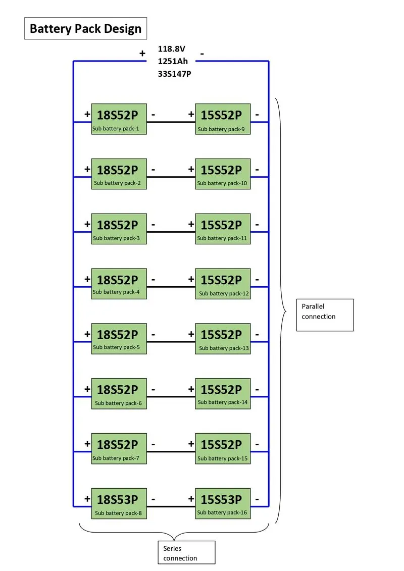
Total result in 2 sub battery packs in sereis one with 18 cells in series and another with 15 cells in series and 8 sub battery pack in parallel each with 52 cells in parallel and any one with 53 to meet the requirment 33S417P.
One sub battery pack configuration is 18S52P and another sub battery pack configuration is 15S52P which results in 33S52P pack with 8 copies. these 8 33S52P are connected in parallel (One of the pack with 33S53P) to make 33S417P.
Basic connections block diagram:
Back line indicates the series connection
Blue Line indicates the Parallel connection
Each 18S52P pack is connected in series with the each 15S52P pack results in 33S52P
All 8 33S52P(18S52P+15S52P) are connected in parallel results in 33S417P
Note that last pack in parallel connection contains as 18S35P series with 15S53P pack, one parallel connection is increased in that sub pack to meet the Requirement of 33S147P
2)Draw the BMS topology for this battery pack.
Battery Management Sytem (BMS):
BMS Topologi used in this battery pack is Master and Slave BMS Topologi. Because the total battery pack is made of sub battery packs so controlling and manufacturing will be easy.
Master and Slave BMS which has number of slave controllers are 16 and a Master controller which can handel 16 slaves.
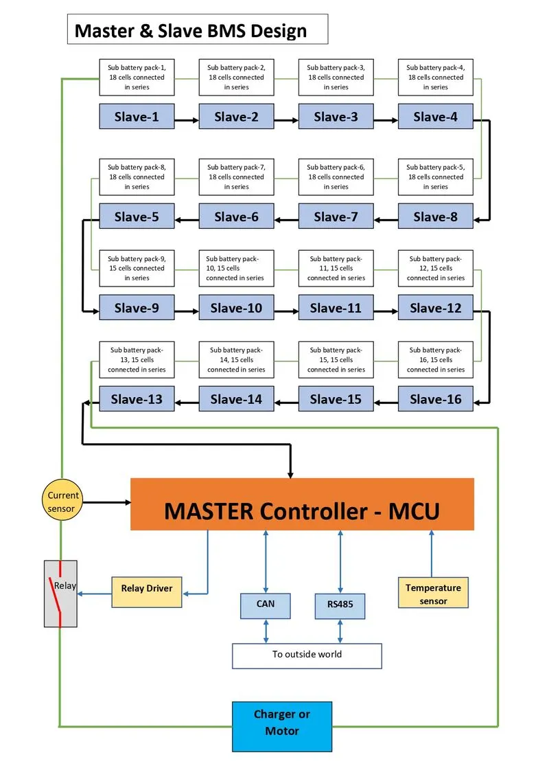
It consisting of input sensors of volatge,current and temperature. The voltage sensor analog signal is converted to digital signal by AFE, the current sennsor analog signal is converted to digital signal by the MCU or we can connect the ADC converter between the Current sensor and MCU, the temperature sensor analog signal is converted to digital signal by the MCU or we can connect the ADC converter between the Temperature sensor and MCU. The Realy module control the Realy which make or brack the circuit by the command given be the MCU. The CAN and RS485 are Communication protocalls to the Outside world.
The Blocks inside the red line are the BMS blocks. It isdesigned with the three 18 cell Slave controller which is AFE, it converts the anolog signal from voltage sensor in the battery to Digital signal. The 3 Slaves are connectes in seres as shown, the salve-1 will collect the data feom module-1 and send to slave-2, slave -2 will collect the data from module-2 , now the salve -2 consisting the data of slave-1 and 2 and it sends the both the data to slave-3, the save-3 will collect the data from module-3, now the slave-3 consisting the data of slave-1,2 and 3, like continues for all 16 slaves and at last all the data is send to Master controller which is MCU. It control the battery pack according to the protocals which is given to MCU.
Note that all the slave have a capacity of 18 cell series connection even though half of the sub battery packs have only 15 series cell besuse if we want to upgrade the capacity we can do by increasing Ah of battery pack i.e., by incresing the number of series cells. It makes easy to upgrade the battery pack but in a limitted way.
Centralized:
- It is a single controller is connected to the battery cells through a multitude of wires
Distributed:
- It is a BMS board is installed at each cell with just a single communication cable between the battery and a controller
Modular:
- It is a few controllers each handling a certain number of cells with communication between the controllers
- Here we mainly used the Master Salve topology because This architecture comprises of the Master and Slave BMS units.
- so by this The slave unit monitors balances and controls a group of battery cells within the battery module.
- It communicates with the master unit through a communication interface.
- The Master unit is responsible for state estimation control of Power Distribution Unit PDU and external communication.
- The master-slave BMS is similar to a modular system in the sense that it uses multiple identical modules the slaves each measuring the voltage of a few cells.
- However the master is different from the modules and does not measure voltages.
- It only handles computation and communications.
Importance of BMS Architecture for EV Battery Systems
- Measurement Precision
- Connection Reliability
- Expansion Versatility
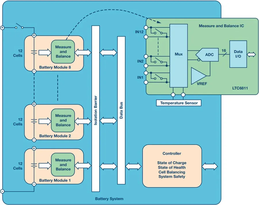
- Here The main function of Battery Management System BMS is to ensure that the battery is protected and any operation out of its safety limit is prevented.
- It monitors the battery pack's state of charge SOC along with the state of health SOH
Battery management system (BMS) is technology dedicated to the oversight of a battery pack, which is an assembly of battery cells, electrically organized in a row x column matrix configuration to enable delivery of targeted range of voltage and current for a duration of time against expected load scenarios. The oversight that a BMS provides usually includes:
- Monitoring the battery
- Providing battery protection
- Estimating the battery’s operational state
- Continually optimizing battery performance
- Reporting operational status to external devices
Here, the term “battery” implies the entire pack; however, the monitoring and control functions are specifically applied to individual cells, or groups of cells called modules in the overall battery pack assembly. Lithium-ion rechargeable cells have the highest energy density and are the standard choice for battery packs for many consumer products, from laptops to electric vehicles.
While they perform superbly, they can be rather unforgiving if operated outside a generally tight safe operating area (SOA), with outcomes ranging from compromising the battery performance to outright dangerous consequences. The BMS certainly has a challenging job description, and its overall complexity and oversight outreach may span many disciplines such as electrical, digital, control, thermal, and hydraulic.
Battery management systems do not have a fixed or unique set of criteria that must be adopted.
The technology design scope and implemented features generally correlate with:
- The costs, complexity, and size of the battery pack
- Application of the battery and any safety, lifespan, and warranty concerns
- Certification requirements from various government regulations where costs and penalties are paramount if inadequate functional safety measures are in place
There are many BMS design features, with battery pack protection management and capacity management being two essential features. We’ll discuss how these two features work here. Battery pack protection management has two key arenas: electrical protection, which implies not allowing the battery to be damaged via usage outside its SOA, and thermal protection, which involves passive and/or active temperature control to maintain or bring the pack into its SOA.
Electrical Management Protection: Current
Monitoring battery pack current and cell or module voltages is the road to electrical protection. The electrical SOA of any battery cell is bound by current and voltage. Figure 1 illustrates a typical lithium-ion cell SOA, and a well-designed BMS will protect the pack by preventing operation outside the manufacturer’s cell ratings. In many cases, further derating may be applied to reside within the SOA safe zone in the interest of promoting further battery lifespan.
We can also use the combination of 8 Master and slave BMS i.e., 2 slaves 18S52Pa and 15S52P and a master controller of 8 numbers. For all master control will have one single controller or all the 8 master controllers can directly connected to the MCU. But its costly and complicated process.
Conclusion:
The battery pack was made to design as 33S147P divided into sub battery packs which is combination of 18S52P series with 15S52P, this combination is paralled with 8 copies as shown above toatl results in 33S147P with capacity of 150Kw with 120V.
To charge and discharge the Total battery pack Master and Slave BMS topology is used which is efficient in all ways like cost, design,control and instalation.