Project 1
PROJECT:- Design and develop a PWM-controlled fan load with DC Moter.
Objective: To model a fan-type load in Simulink and control its speed by using the PWM method
Abstract: The primary emphasis of this work is to model a DC motor driven by an input signal that approximates a pulse-width modulated signal. These signals are fed to the motor using an H bridge circuit. Further, we focus on the implementation of speed control of a fan at the motor output. We assume that the change of operating speed of the fan is through stepwise modulation through a fan regulator
Keywords: PWM, H bridge, DC Motor
>Introduction
This paper presents the work for the design of the fan speed control system using Pulse Width Modulation by establishing a connection between an H bridge circuit and a Dc motor. A fan-type load equation has been used to analyze the output results instead of a physical model of a fan in Simulink. The fan speed is varied according to the input voltage using the PWM technique.
By changing or modulating the timing of these pulses the speed of the motor can be controlled. A stepwise change in the speed variation is given and the full load speed is observed. In this model, all input ports of the H-Bridge block except the PWM port are connected to the ground. As a result, the H-Bridge block behaves as follows:
- When the motor is on, the H-Bridge block connects the motor terminals to the power supply.
- When the motor is off, the H-Bridge block acts as a freewheeling diode to maintain the motor current.
>Pulse Width Modulation
Pulse Width Modulation, or PWM, is a technique for getting analog results with digital means. Digital control creates a square wave, a signal switched between on and off. This on-off pattern can simulate voltages in between full-on and off by changing the portion of the time the signal spends on versus the time that the signal spends the duration of "on time" is called the pulse width. To get varying analog values, we change or modulate, that pulse width.
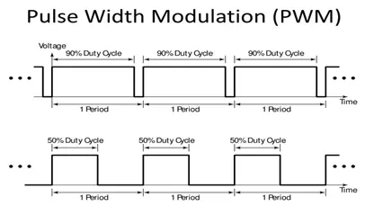
Figure 1:PWM modulation
>Load characteristics
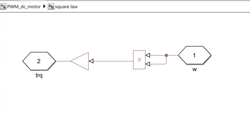
The torque speed curve of a load is a plot showing its torque requirement on the y-axis versus the speed on the x-axis. It’s the torque requirement of the load from zero speed to full speed. It is application/load specific and varies with different load types. Loads like centrifugal pumps and fans follow the quadratic speed torque curve, where torque varies square times. These are also called constant torque loads or applications.
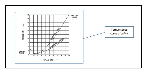
Figure 2:Torque-Speed characteristics of FAN
>Model Diagram in Simulink:-
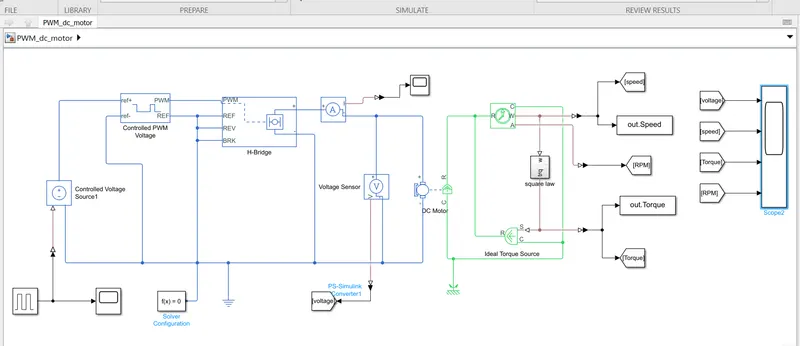
Figure 3:Simulink model of the PWM Controlled Fan load using DC motor
Subsystem:-
>Model description
The DC Motor block uses manufacturer datasheet parameters, which specify the motor as delivering 10W mechanical power at 2500 rpm and no-load speed as 4000 rpm when run from a 12V DC supply. H-bridge block represents a motor drive. The Controlled PWM Voltage block can drive the block in Averaged mode.
>How to model in Simulink
A detailed explanation of how to model this example is given in the dashboard of the Introduction to HEV using Matlab/Simulink course along with the introductory theory part and discussion of results as video tutorials
>Conclusion
A PWM-controlled DC motor using an H bridge circuit was modeled in Simulink and results were analyzed. The output plots justified the theory discussed. The load torque characteristics of a fan is obtained. The full speed was observed for a full voltage of 12V from the DC motor.