Project 1
ENGINE WIRING HARNESS ROUTING
AIM:
To route the wiring harness on given Engine and prepare flatten view drawing in CATIA V5. All types of packaging rules have to be considered while routing the harness. Also, Industry best practices should be demonstrated in design. All the necessary details like clearance, clipping/clamping selection, harness fixing requirements, harness continuity should be provided in order to design wiring harness.
INTRODUCTION:
A wire harness, also commonly referred to as a wiring harness, is an exterior sheath used to cover some types of electronic wires. Generally, wiring harnesses are made of thermoplastic or thermoset materials that can help protect the cables from the environment.
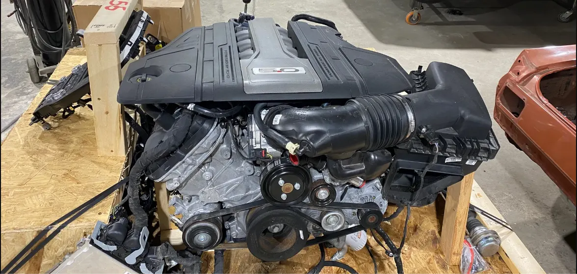
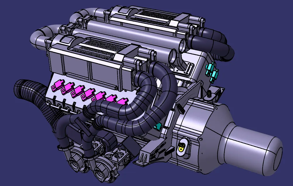
· The below figure shows the 16 valve Engine where 8 cylinders are placed on the right side and 8 cylinders are placed on the left side.
· There is total of 16 injectors, where 8 injectors are used for 8 cylinders on right side and 8 injectors are used for another 8 cylinders on left side.
· Also, there are 4 cam-shaft sensors, so there are totally 20 sensors that we have to connect electrically.
· Generally, 4-pole connectors are used for fuel injectors of the engine.
· The engine will also have an interconnection connector which will connect the engine to other parts of the vehicle. We will be using a 12-pole electrical connector with a mounting clip feature as an interconnection connector.
· The plastic guiding channel used in this harness should be made of a material that can withstand at least 150 degrees Celsius.
· The bend ratio for all the bundle segments should be 1.4.
1. DESIGN METHODOLOGY:
Step 1:
Download the engine CAD data and required connectors CAD data from the given source.
DEFINING THE CONNECTORS, CLAMPS, CLIPS AND MOUNTING ELEMENTS ELECTRICALLY.
STEP 2: Connector definition:
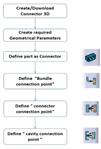
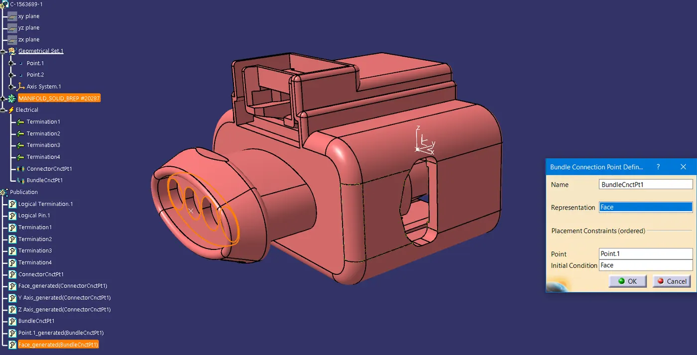
· Following Parameters are required to defined for any connector -
· Geometry Parameters - Points & Co-ordinate system (Axis)
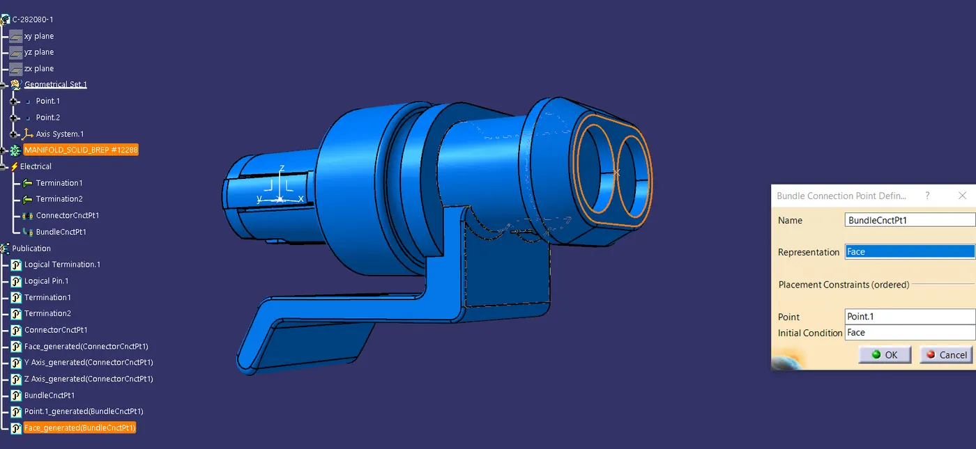
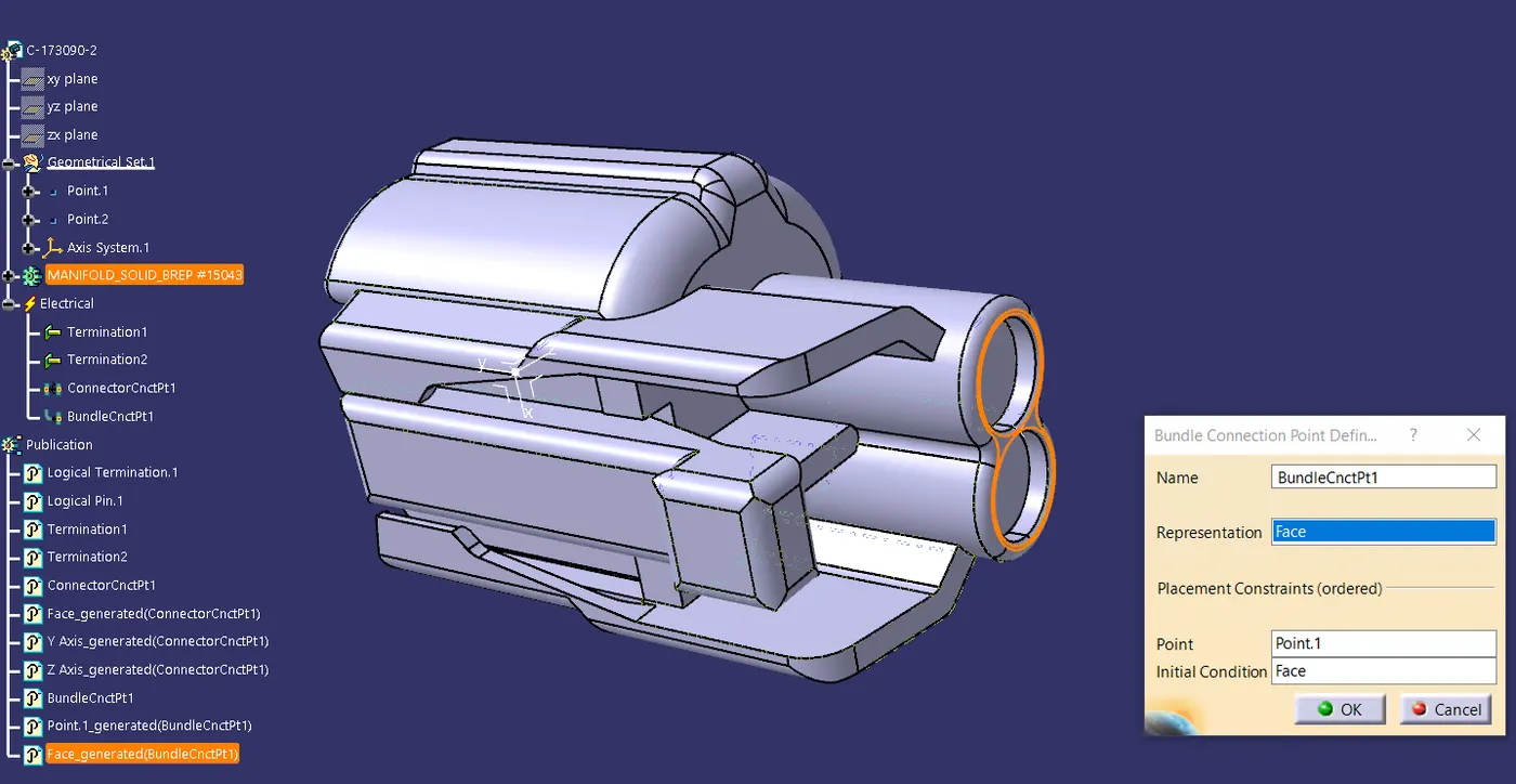
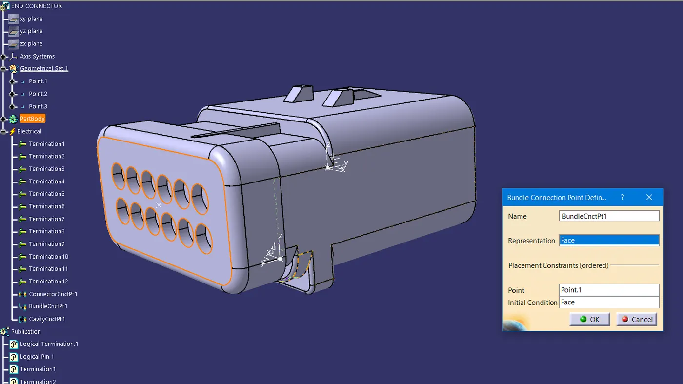
· Connector connection points - This point is used for the connection of one connector to another connector.
· Harness bundle entry point - This point defines where the harness bundle segment point will end when routed to the electrical connector.
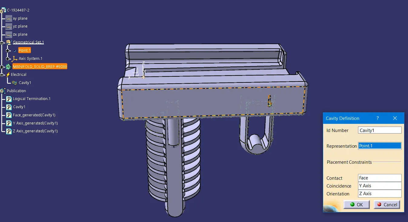
· Cavity connection point (Optional) - This point is used to define the connection of a connector to a connector clip. This only applies to connectors which have the mounting feature for a connector clip.
connector1
connector2
connector3
connector4
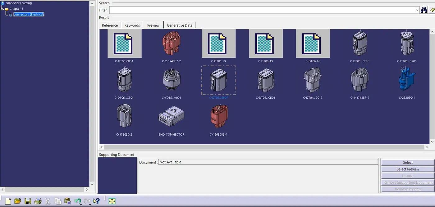
Adding connectors to the catalogue:
cavity
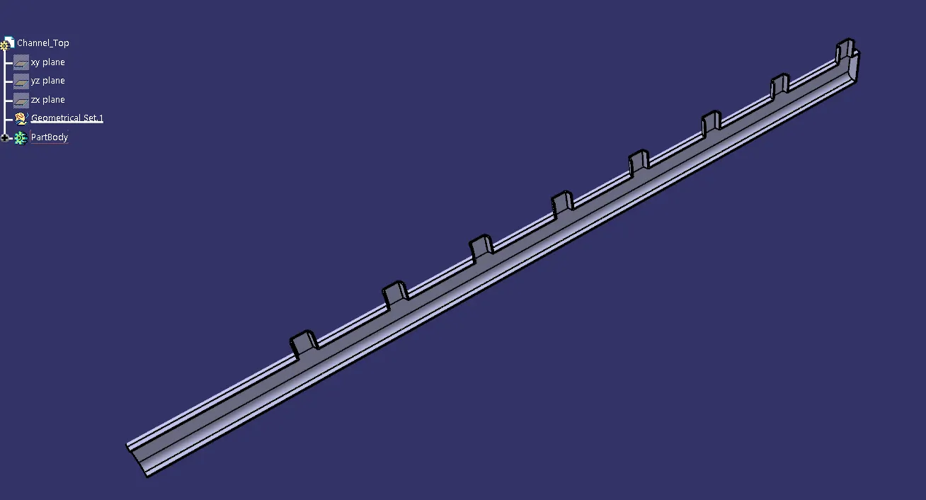
STEP 3- Download and define the plastic channel electrically:
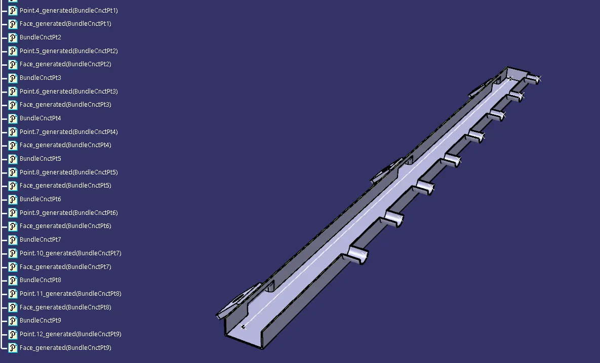
· Create bundle entry point and exit point.
· Create a line curve between the main entry and exit points for creating the multi-branchable using external curve inside the channel
· Create 8 bundle entry points on the openings for connecting the injector connectors.
· Using the geometrical parameters, define the channel electrically.
· Create define bundle entry points using the “define bundle connection point option.”
bottom
top
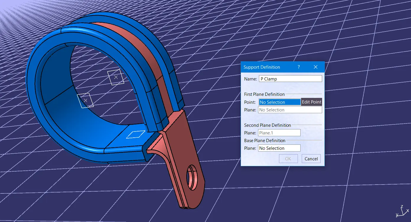
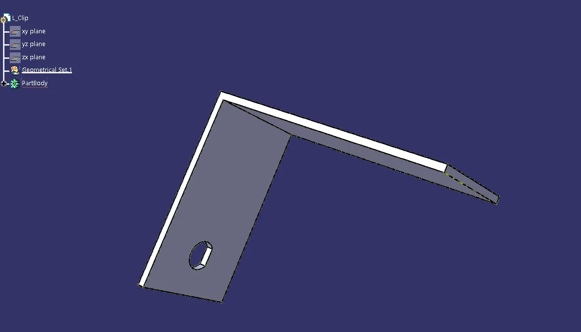
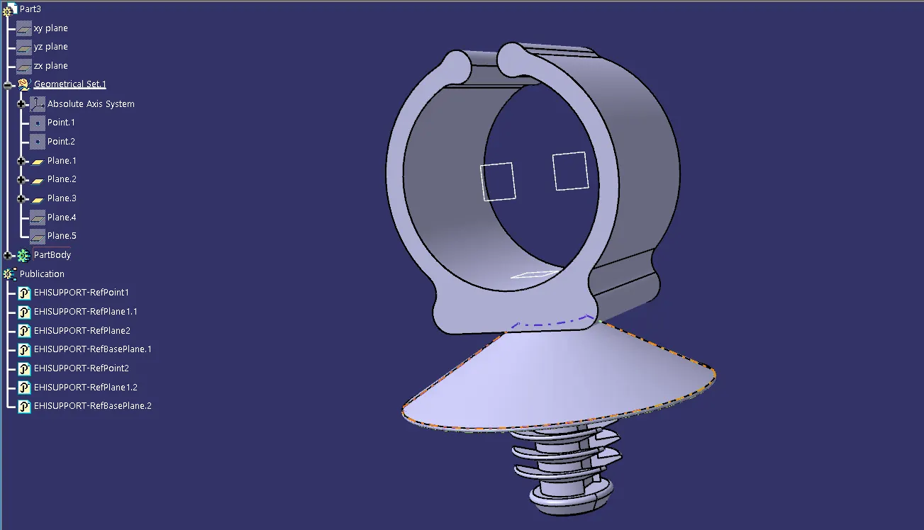
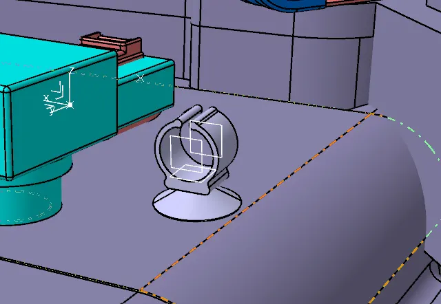
STEP 4- Dowload and define p-clamp, l-clamp and fir tree clip:
P – Clamp
L – Clamp
Fir tree clip
2. ASSEMBLY PROCEDURE & PART POSITIONING:
· After given the electrical properties to all the connectors & required parts then start the Preparation of Harness context assembly.
· Create a master product file (ASSY_ENGINE_HARNESS_CONTEXT) then import engine file under it and after that create a sub-level product file named (ASSY_GEOMETRY_BUNDLE) and save it.
· Once Geometrical Bundle is created select the "Geometrical Bundle" command and then click on Product (ASSY_GEOMETRY_BUNDLE) Icon in Model tree to convert it in to an Electrical Assembly.
· Insert Harness Connector, clamps, clip and mounting Components into the Geometrical Bundle. Before Inserting the components, ensure that all the required components have been electrically defined.
· Once the required components were defined electrically, then insert them using Catalogue Browser command or using existing component command.
· After inserted all component, position them it according to the engine reference. Before start routing, ensure all the components in its desired location according to surrounding data.
· If not then place and position the components by using any of the following commands like Manipulation, Translation or Rotation, Snap, Smart Move, Compass.
SOME IMPORTANT PACKAGING RULES TO BE CONSIDERED DURING WIRE HARNESS ROUTING AND PLACING OF THE CLIPS AND CLAMPS:
· P - Clamps, Fir tree clips and other clips can be added to the Geometric bundle as they are electrically defined and are part of the Wire harness routing and should be provided with the Wire bundle package.
· The minimum bundle length should be 50mm.
· Enough slack should be provided so that the wiring harness does not get damaged during the Engine rocking or starting condition.
· The wire harness routing should be done in such a way that it is easy in manufacturing and serviceability.
· The wire routing should be done keeping in mind the cost effectiveness of the bundle package.
· To avoid the harness routing and clipping in blind zones of the operator during the assembly and the service.
· Additional slack should be given according to the surrounding and harness bending requirements.
· To avoid giving excess slack and avoid giving slacks wherever not necessary.
· To provide proper slack at end connectors so that there will be no tension on the wire bundle.
· To avoid sharp edges on the sheet metal parts and if it is not possible then provide protection parts to prevent damage of the wire bundle.
· The minimum distance between two straight connection points should be 200mm.
· The minimum distance between clip and the nearest branching point should be 25mm.
· The minimum distance between two breakout points should be 50mm.
· To limit the number of branches from a single branch point to 4.
First position the fuel injector connector and camshaft connector on the engine.
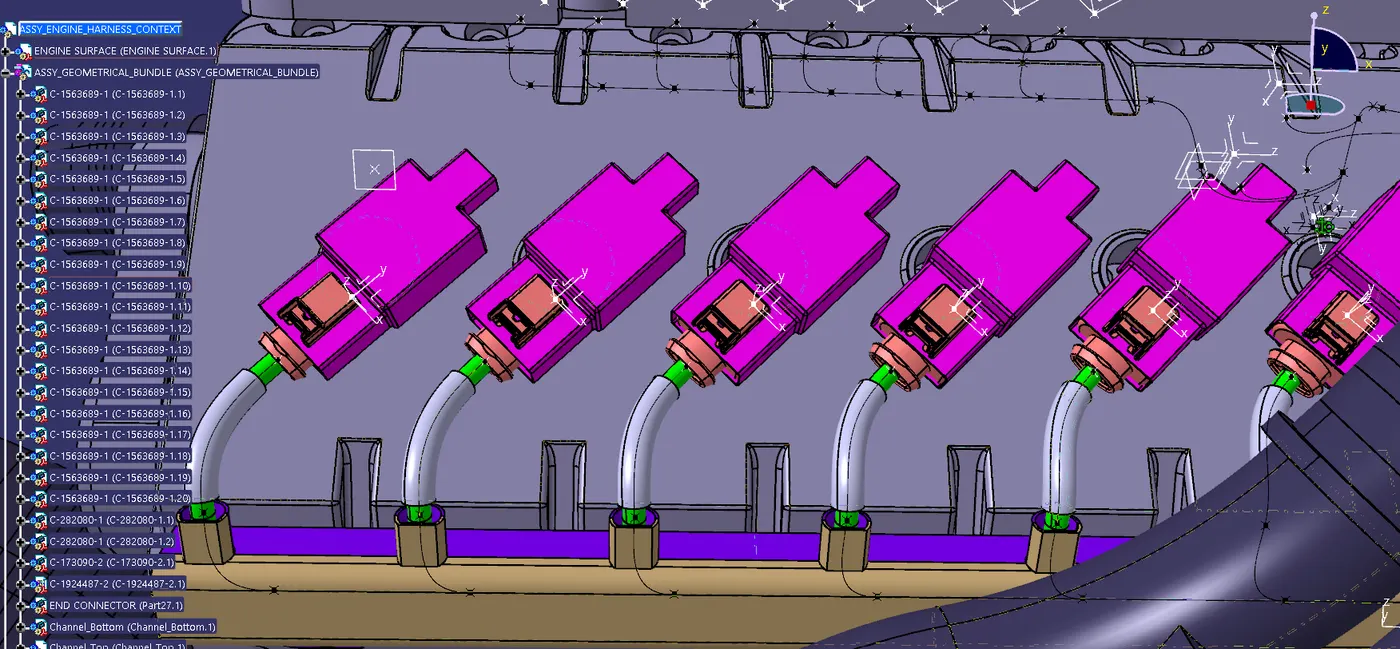
Then add all the other connectors like coolant heat sensor, neutral position sensor and speed sensors.
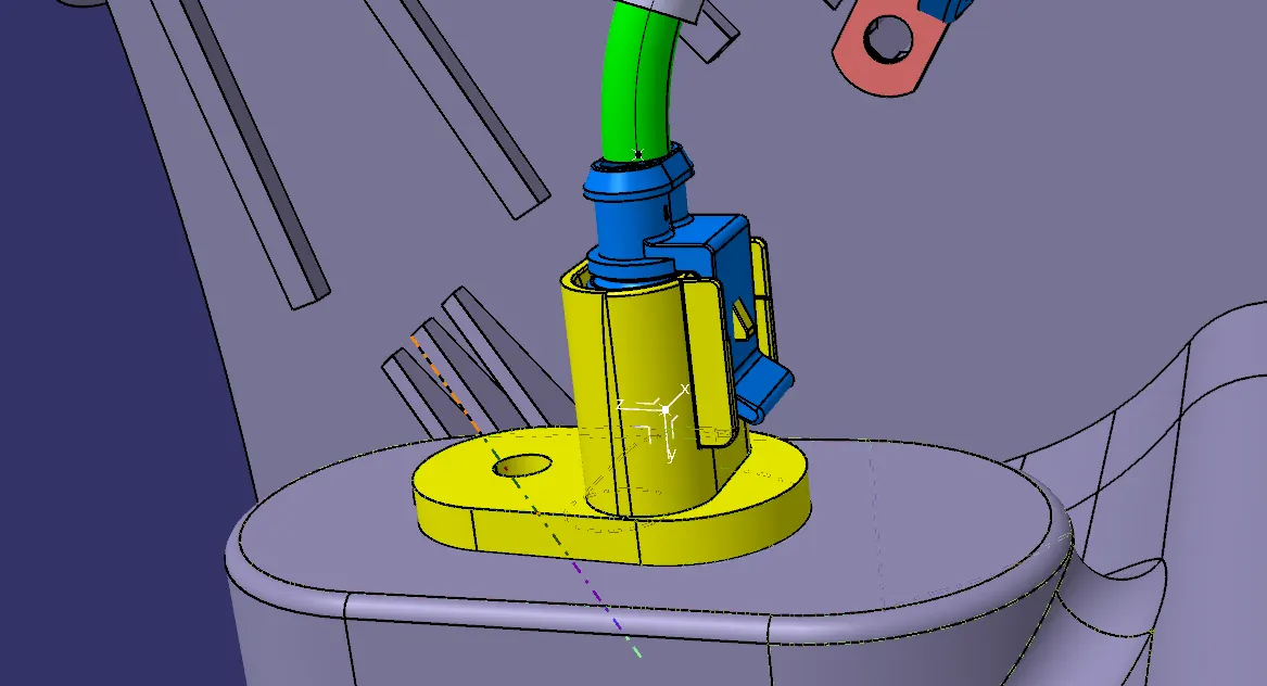
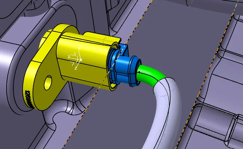
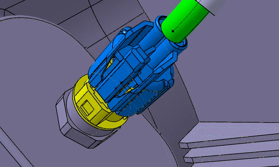
Positioning of interconnection connector and L-clamp support.
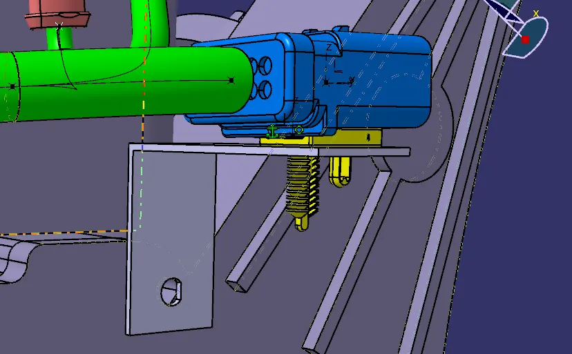
Adding supporting components like p-clamps and fir-tree clip can help the harness bundle provide proper routing and also help to prevent the harness bundles fouling from unwanted mechanical components.
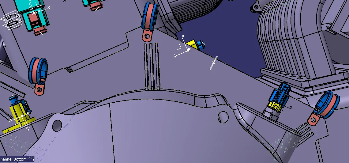
· P - Clamp and the Fir Tree can be placed at required locations to ensure best possible routing for the harness bundles.
· The P – Clamps can be mounted to the holes provided on the Engine block in which the screws to tighten the Engine block.
· The Fir-tree clips are positioned according to the requirement during the wire harness routing.
· After finalization of the routing, we can request the Engine design team to provide the holes for the Fir tree clips as per their location.
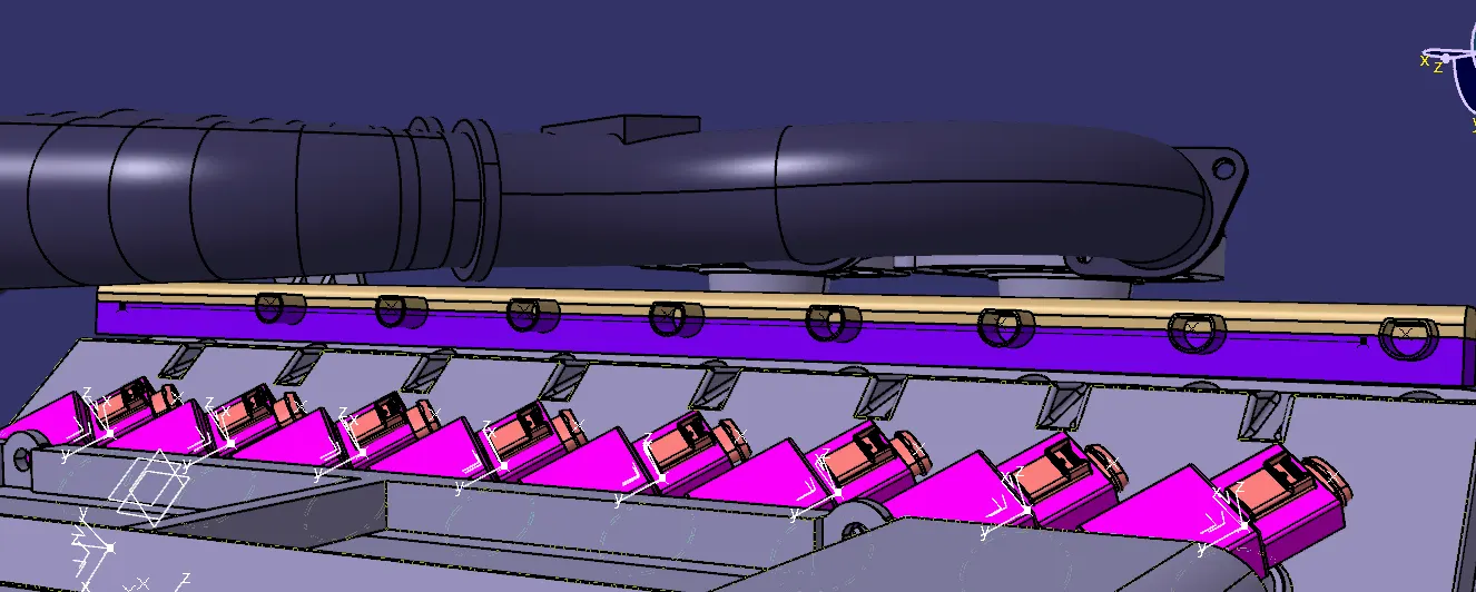
Placement of guiding channels:
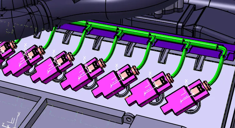
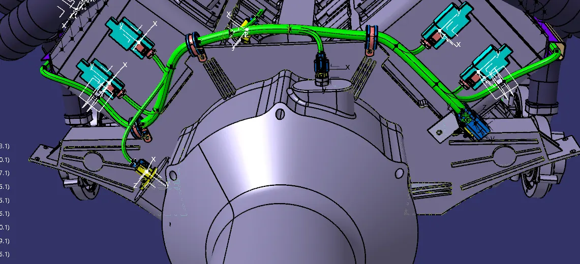
3. BRANCH CREATION:
· Switch to Electrical harness Assembly Workbench.
· Select Multi-Branchable Document Icon.
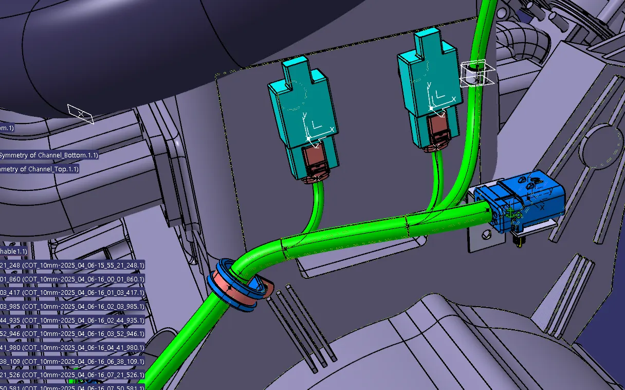
· In the Branch Definition Box (Ref Below Image), give all the required parameters like Diameter, Bend Radius (>1.4), Build mode (slack, Length, Bend, Straight Bend).
· Click Route Definition and select the two components that you need to route or use external curve for creating bundle.
· Click OK.
· Once the multi-branchable is created, Click Add branch point command and define the point on the main branch where the Harness Branch needs to be created.
· After creating the point repeat the steps of multi-branchable creation.
4. ADDING PROTECTIVE COVERING:
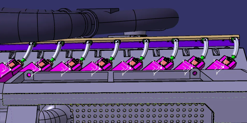
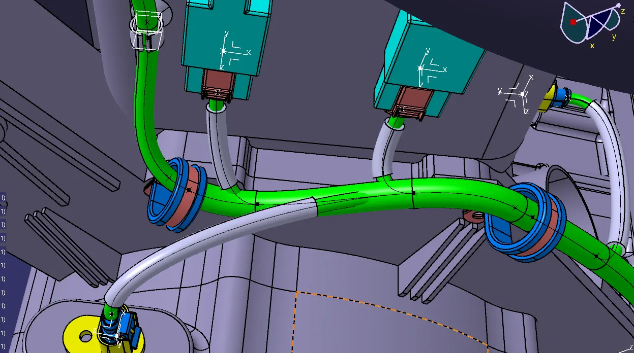
Add protective covering on the required branches by using Protective Covering Command and mention the start and end extremity points.
Switch to Electrical Harness Assembly > Select the Protective Covering > Select the Bundle Segment > Select the size of protective covering > Give its end extremity > Click OK
5. ELECTRICAL CONTINUITY CHECK:
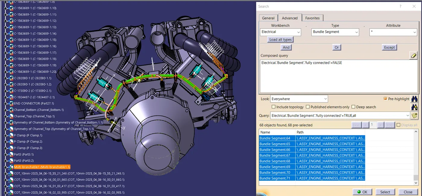
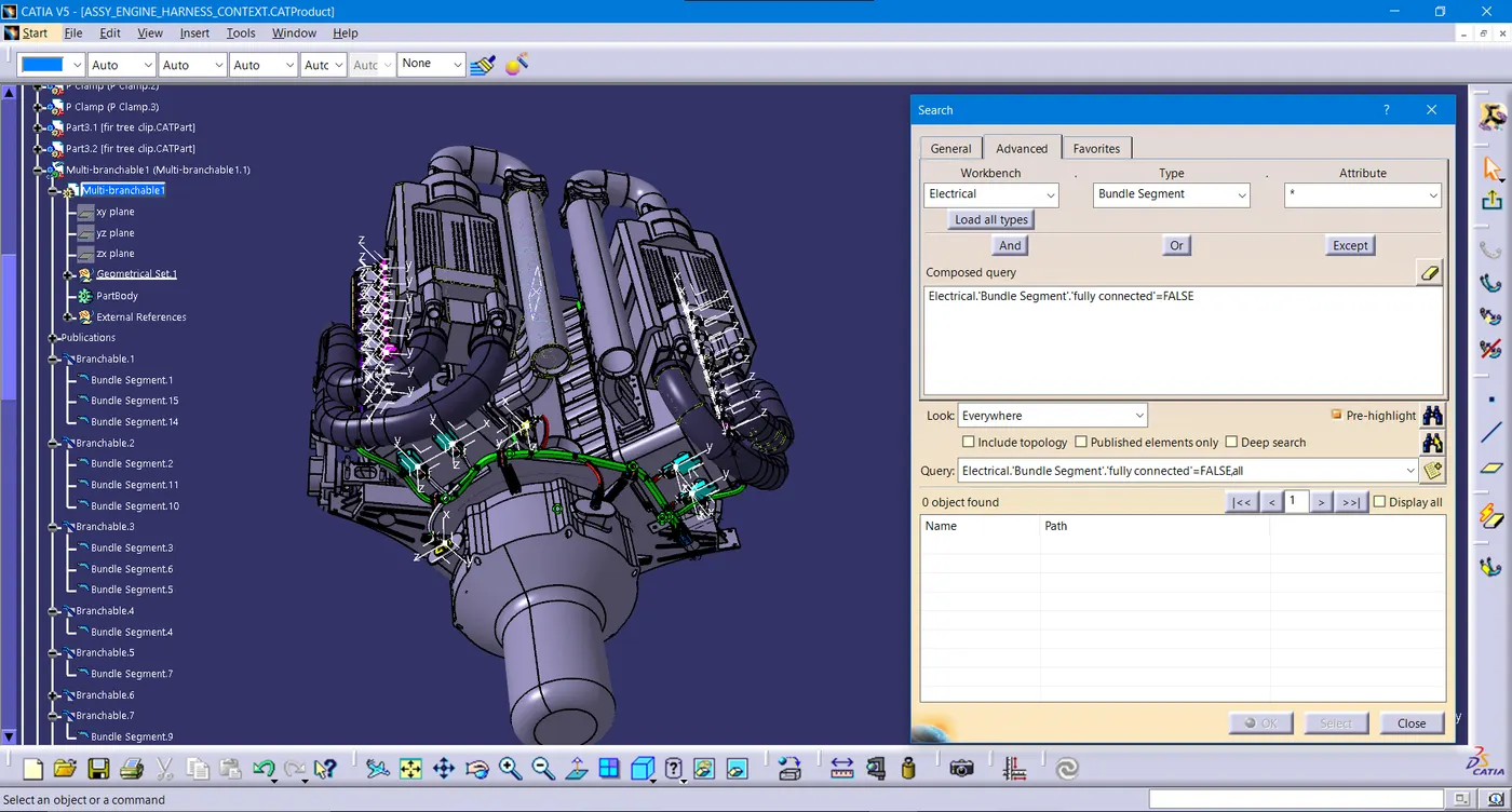
· We need to ensure that the entire bundle is fully connected.
· Go to edit and then click on search command.
· Go to advanced
· Select workbench as electrical, type as bundle segment and attribute as Fully connected
· The select result should be as TRUE or FALSE and the click search to see the connectivity analysis result
6. FLATTENING OF HARNESS ASSEMBLY:
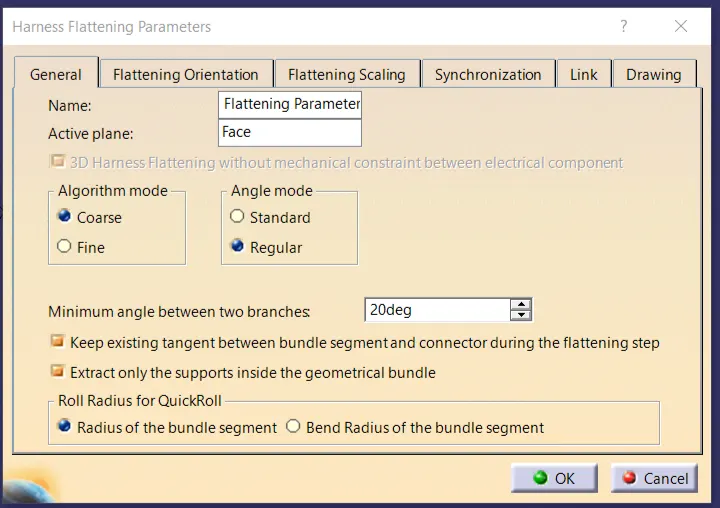
· In order to flatten the Assembly, we have to define the Flattening Parameters in “Electrical Harness Flattening Workbench”
· We have to define the desired plane that we want to work on and Select the desired parameters according to your requirements.
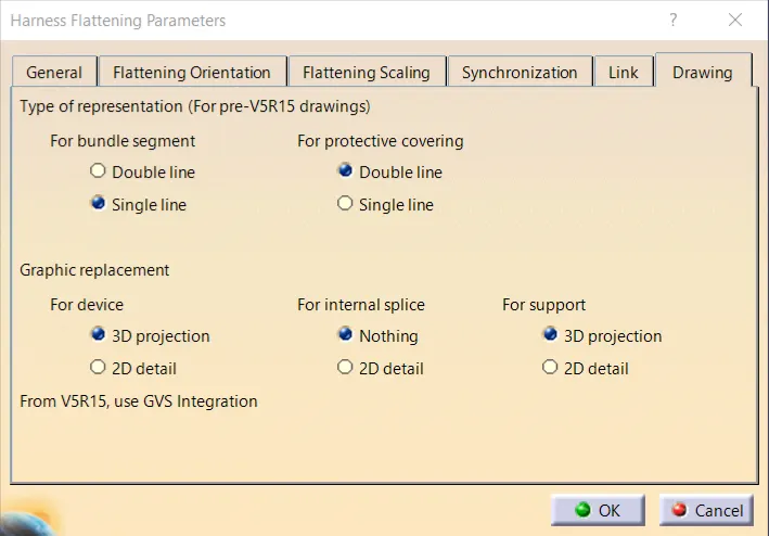
· We have to ensure that the bundle segment, protective covering and devices representation should be different from each other just for recognizing purpose. For that we have to enable parameters like the below image.
· Now, we have to bring Harness Assembly into newly created Flattening Product by using Extract command in 'Electrical Harness Flattening' workbench. Here, we have to tile both the files (Flattening Product file & Harness Assembly source file) vertically.
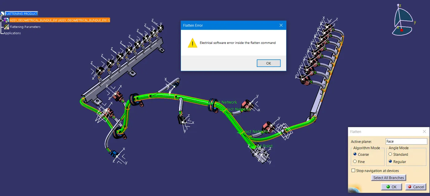
· Now, we have to flatten the given Harness Assembly and for that we have to choose plane or face of the connector after that select all branches of the Harness Assembly.
· Now, we have to use rotate, scale, Roll, Bend etc to make it look representable. After that our resultant flatten file will look like below image.
· In my case, I have a software error “Electrical software error inside the flatten command” because of that I can’t able to do flattening process.
RESULT:
In this project I have successfully routed the wiring harness for the V16 Engine assembly and the flatten-view drawing was prepared in CATIA V5. Various packaging rules and constraints were considered while routing the harness. After finalizing the wire routing, we can request the corresponding Engine design team to provide additional holes for the mounting of Fir tree clips.