Project 1
ENGINE ASSEMBLY:
The given engine assembly part is studied to plan the wiring harness routing initially. The required connectors and other electrical components and supports are mapped. The Initial input given is the part of the engine assembly.
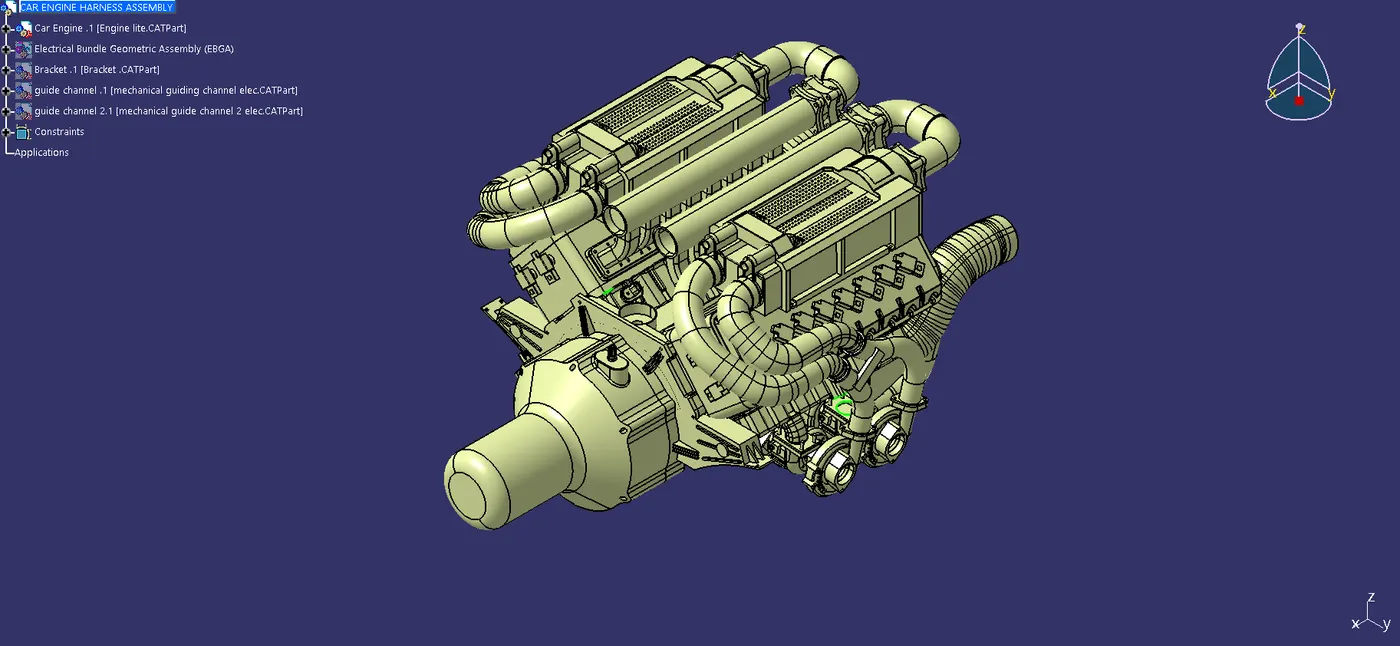
The harness is developed on top of this part provided.
connectors are placed in the respective positions as shown in the image below to the respective sensors.
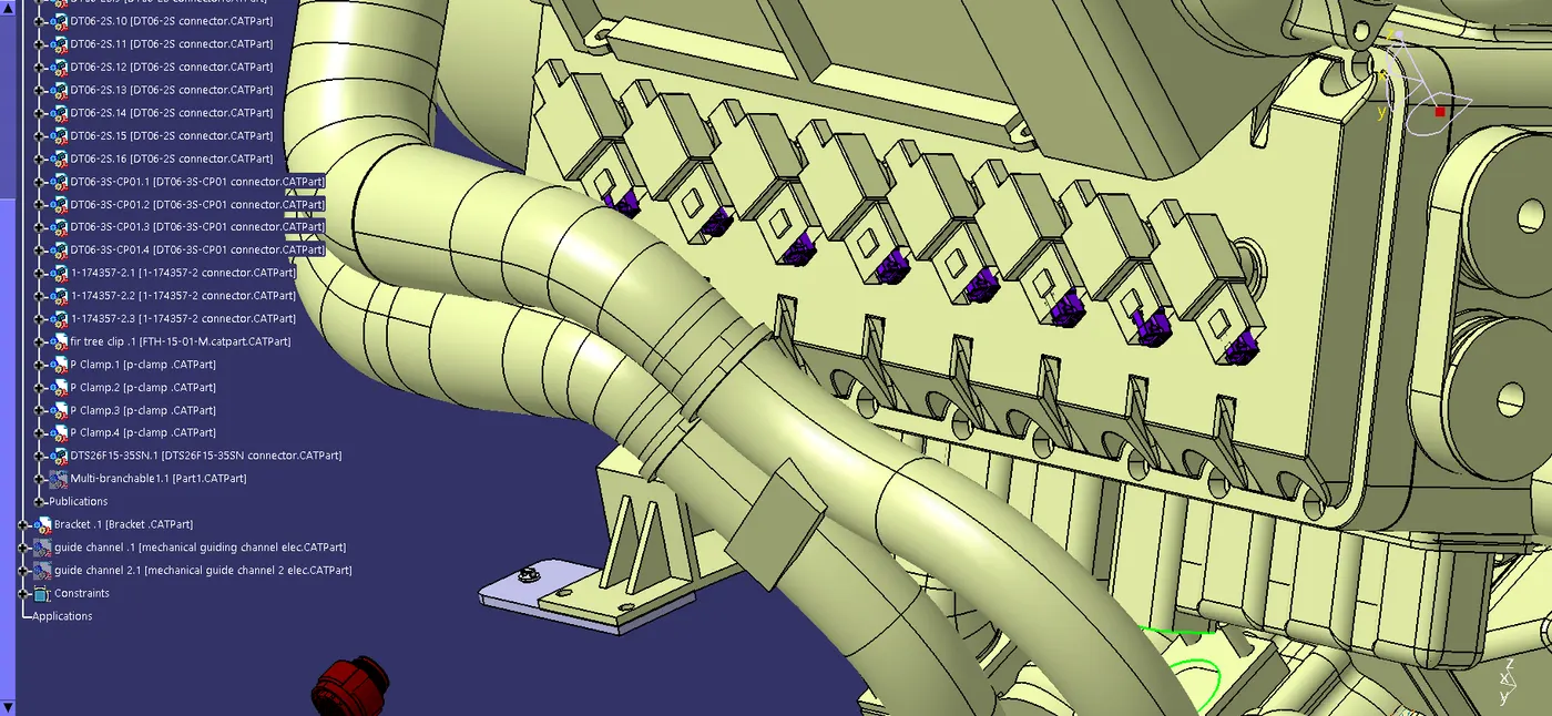
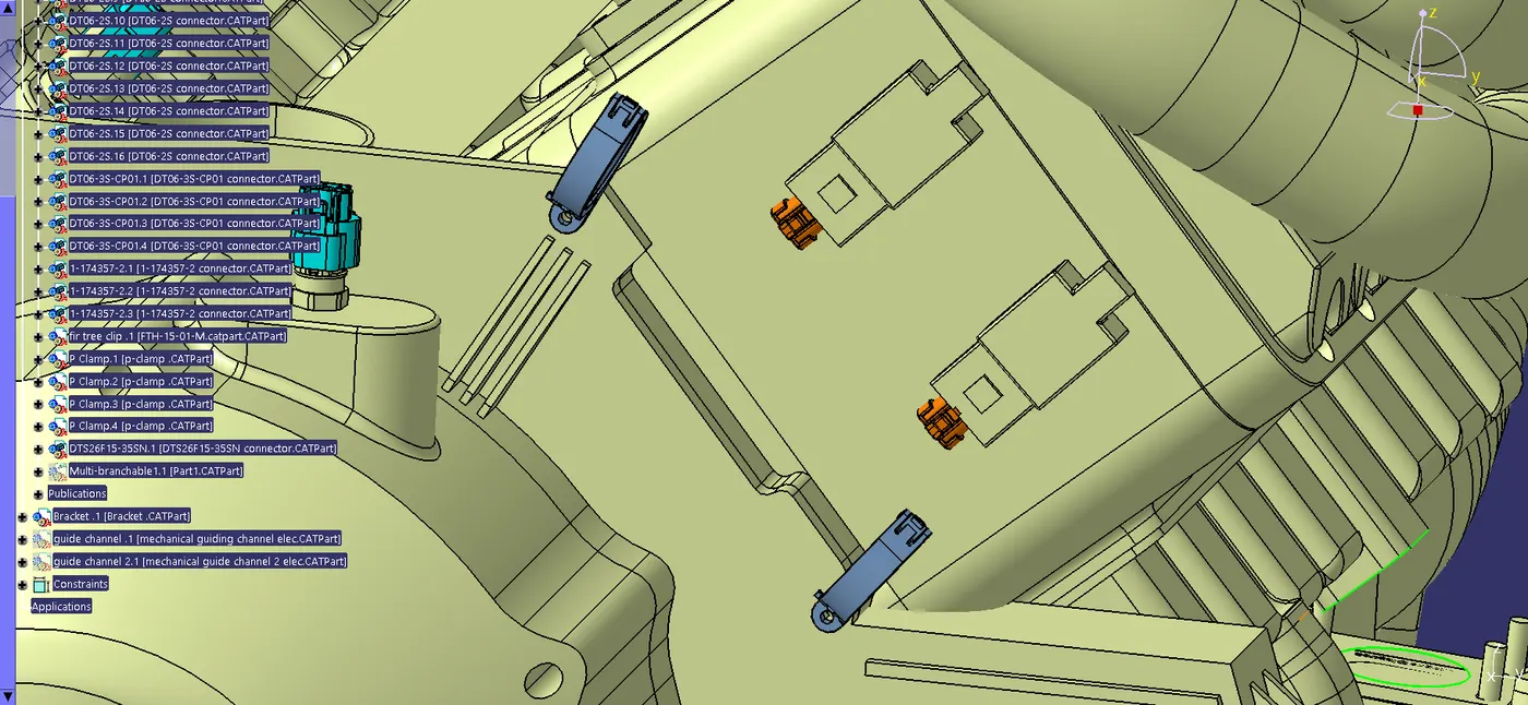
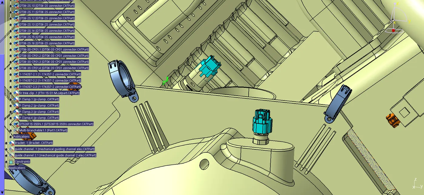
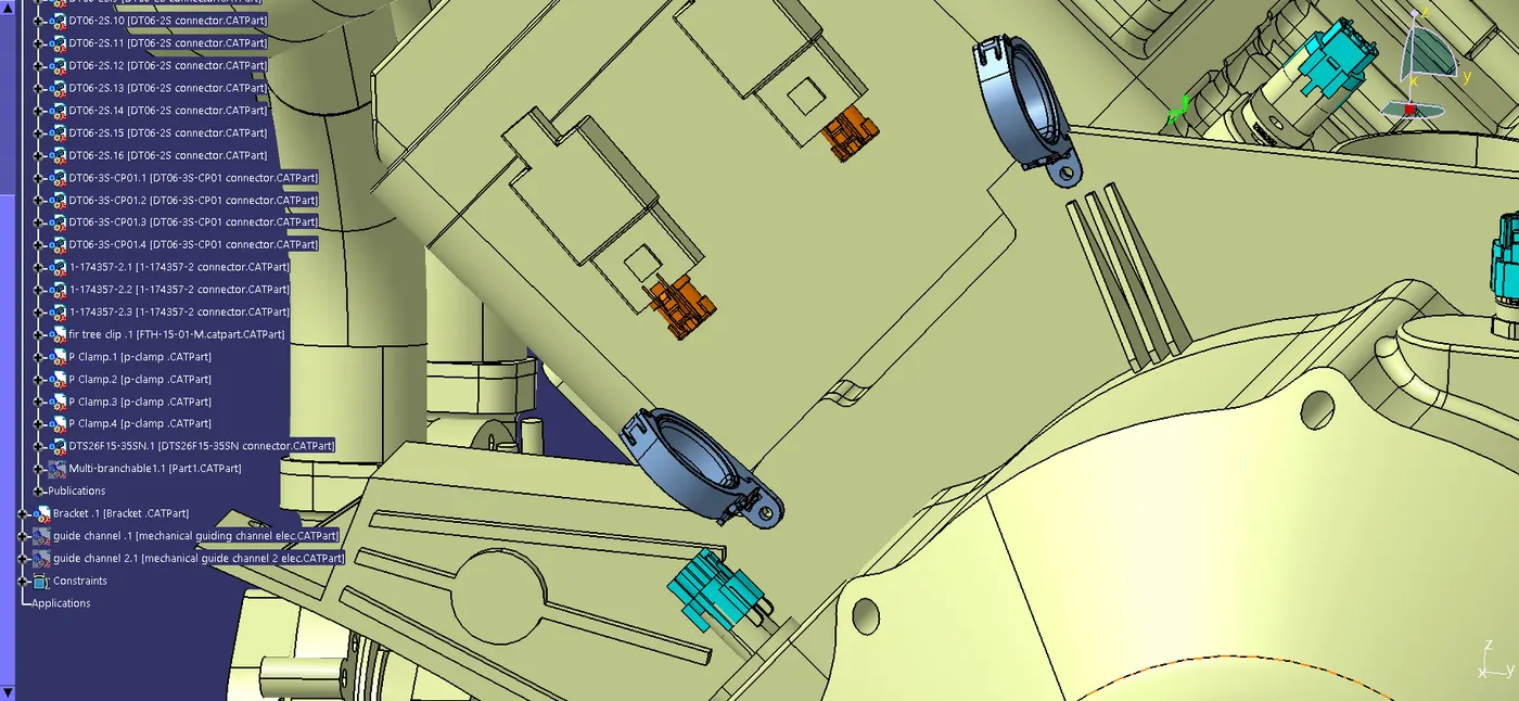
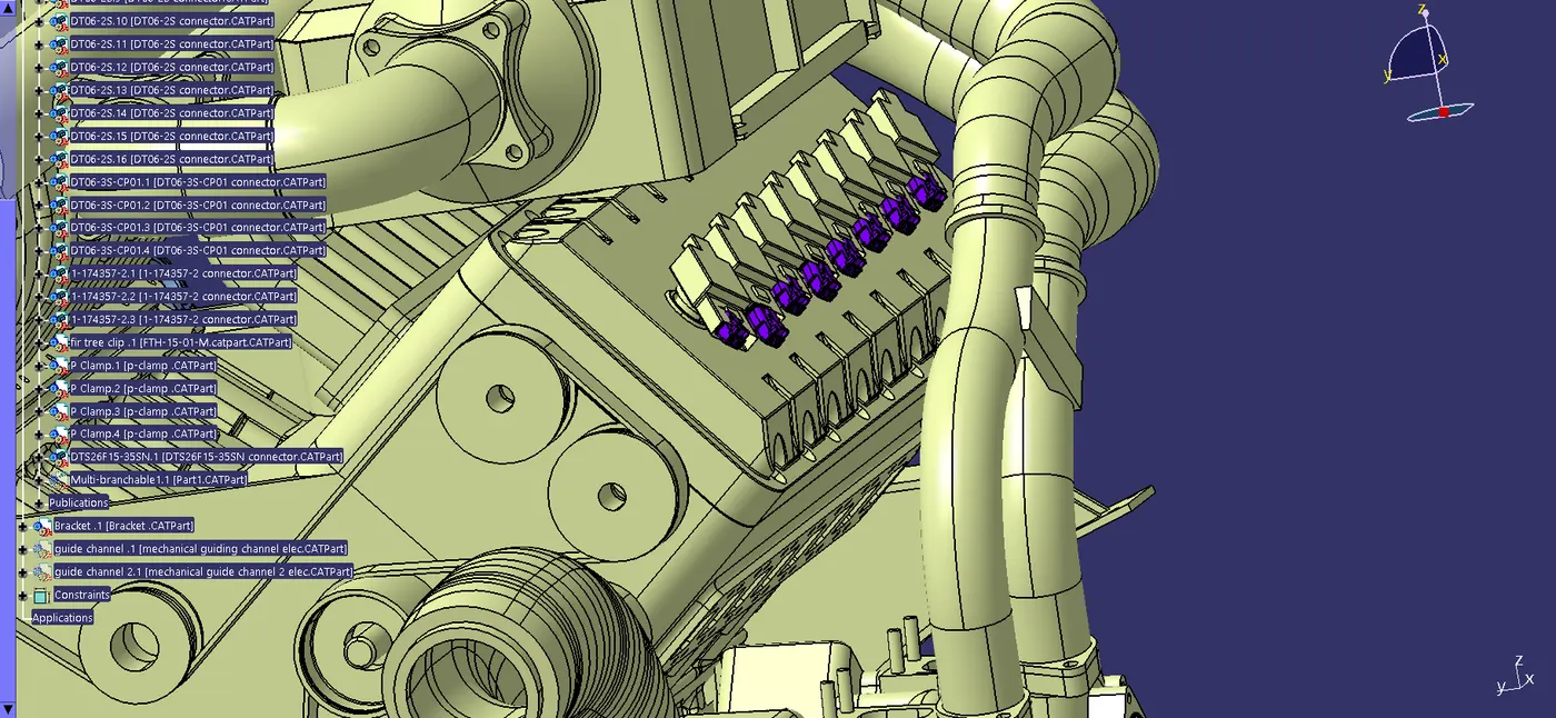
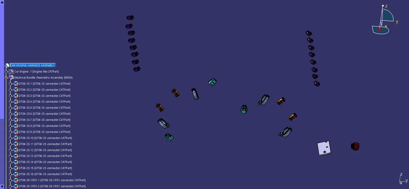
The connectors, p clamps and additional brackets if needed are placed in required positions for routing of the harness. Once the components are placed in the respective positions wiring harness routing can be started. before starting ensuring all the components are electrically defined inside the geometric bundle assembly.
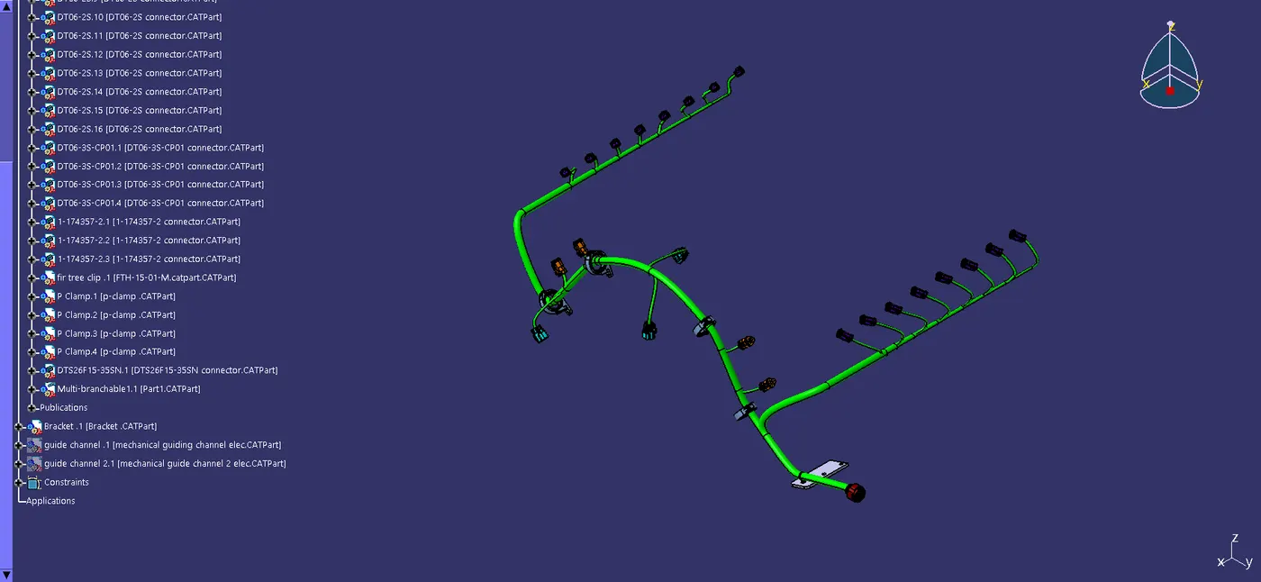
The routing is done and then checked for any incomplete bundle segment connections.
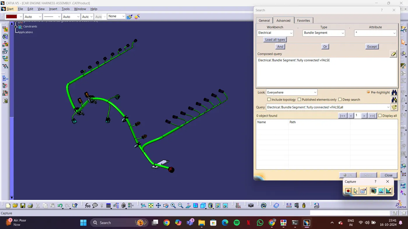
Once the bundles are all connected completely together, we can procced with the flattening of the multi branchable. if not we will be facing issues while flattening.
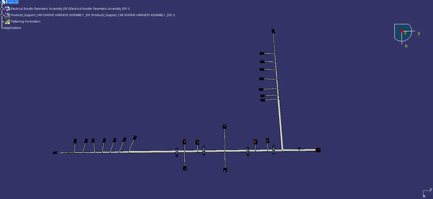
Once the flattening is done we can arrange the branches as per our feasibility. Once the branches are arranged drawing is done.
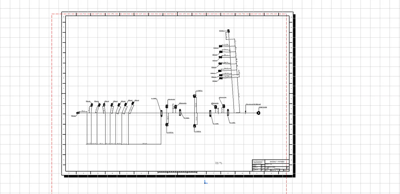
The parts and connectors are named using the annotation command. dimensions for the branches are also defined. Finally the drawing is saved as pdf and as drawing file
SIDE DOOR PANEL:
The given side door panel is studied to plan the wiring harness routing initially. The required connectors and other electrical components and supports are mapped. The Initial input given is the part of the side door panel assembly.
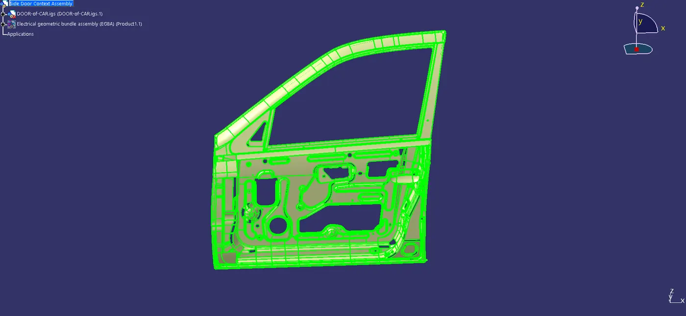
The harness is developed on top of this part provided.
connectors are placed in the respective positions as shown in the image below to the respective sensors.
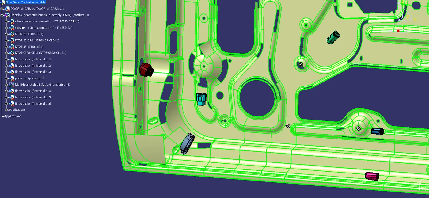
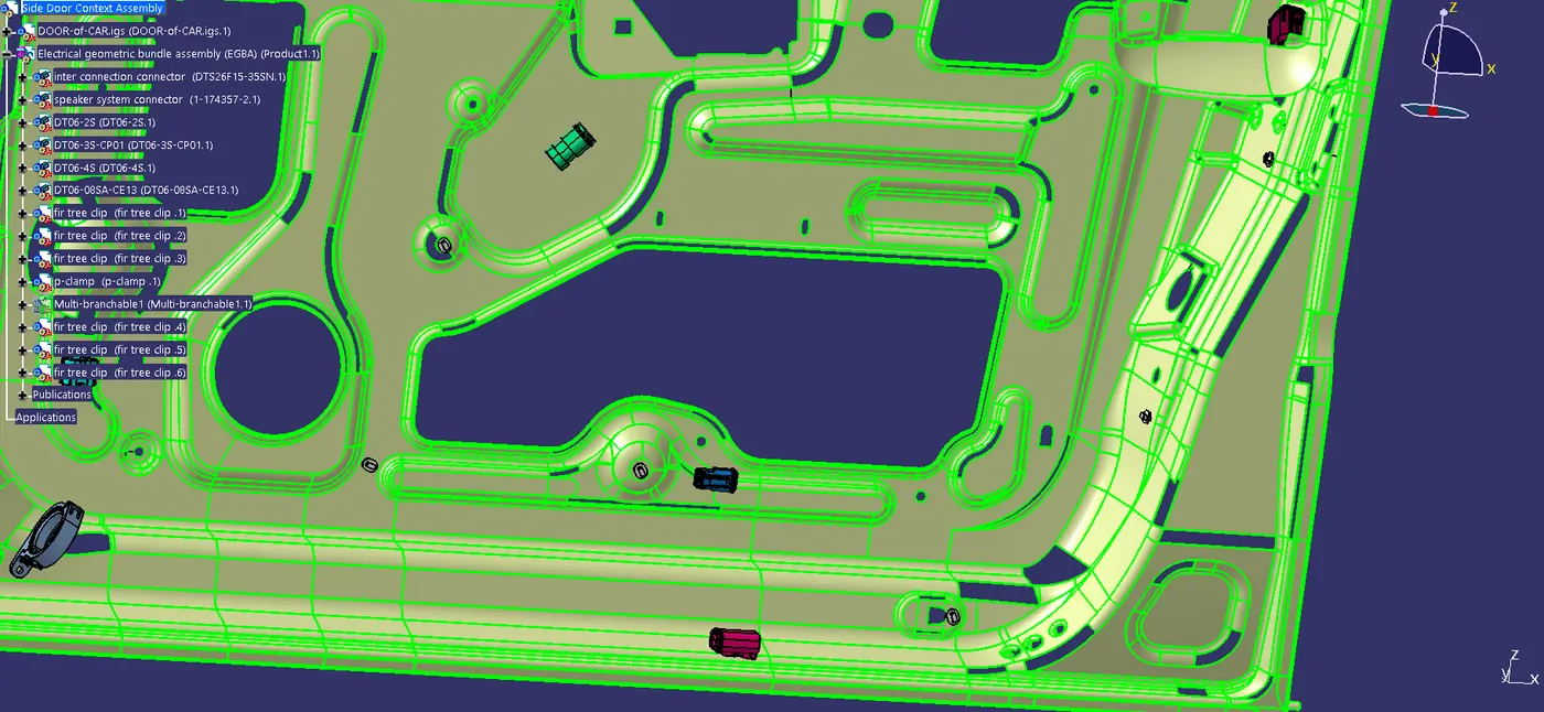
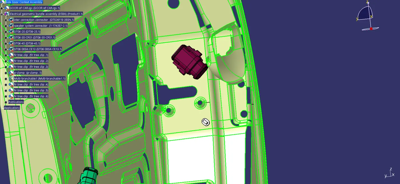
The connectors, p clamps and additional brackets if needed are placed in required positions for routing of the harness. Once the components are placed in the respective positions wiring harness routing can be started. before starting ensuring all the components are electrically defined inside the geometric bundle assembly.
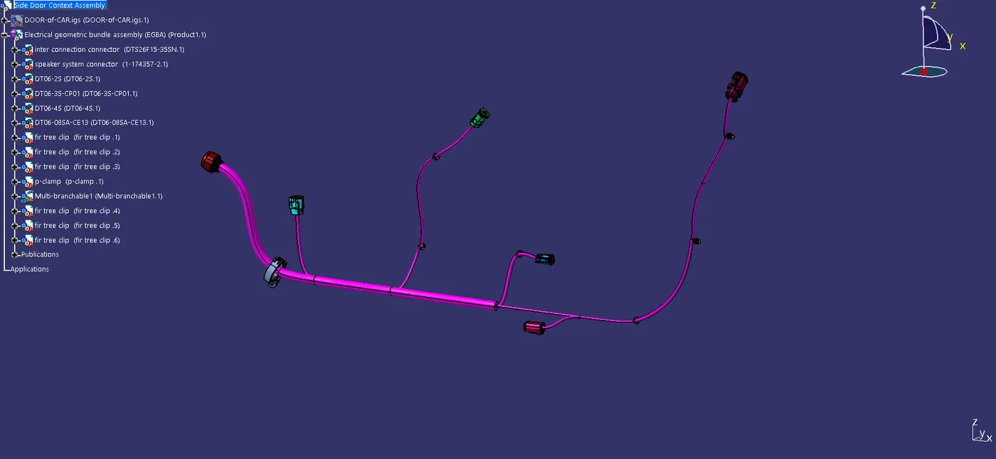
The routing is done and then checked for any incomplete bundle segment connections.
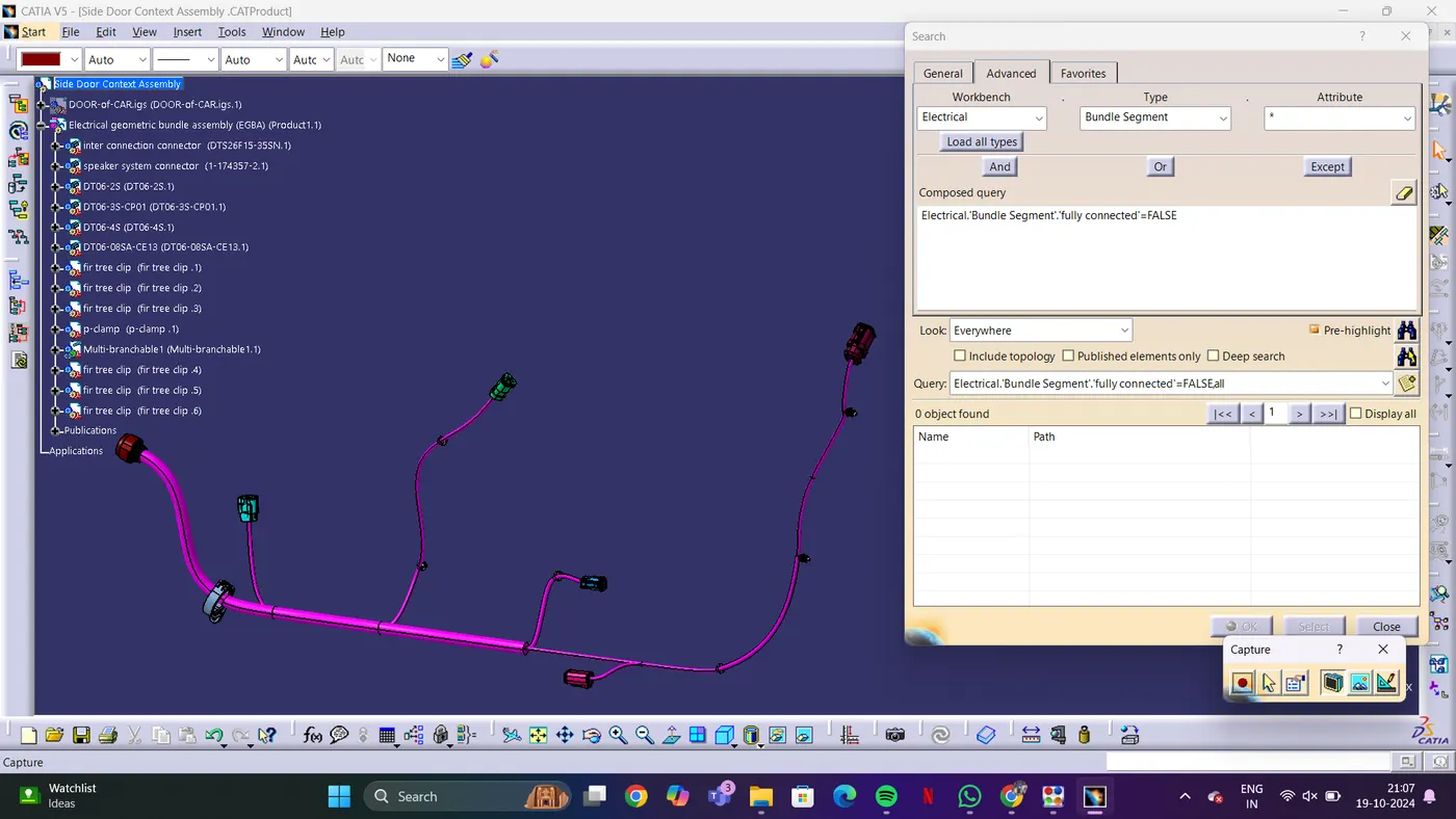
Once the bundles are all connected completely together, we can procced with the flattening of the multi branchable. if not we will be facing issues while flattening.
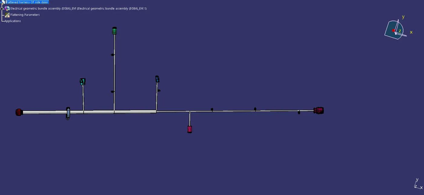
Once the flattening is done we can arrange the branches as per our feasibility. Once the branches are arranged drawing is done.
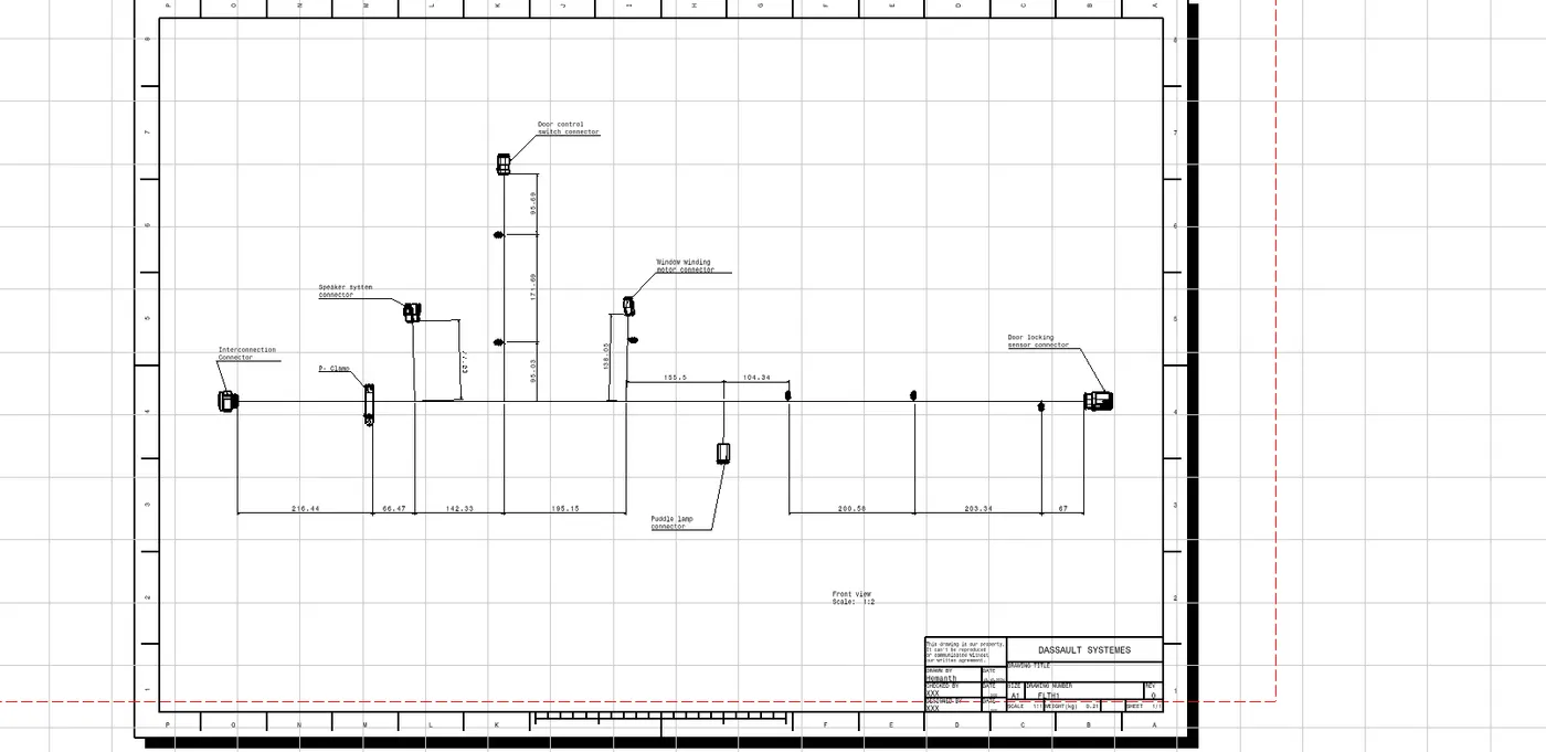
The parts and connectors are named using the annotation command. dimensions for the branches are also defined. Finally the drawing is saved as pdf and as drawing file
The parts file link is attached below as file size is larger than 20 mb.
Link:
https://drive.google.com/drive/folders/1hKXa5ARnkRinqXza_5duzoJAybcwsT-w?usp=sharing