Project 1
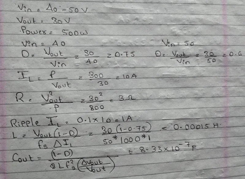
buck converter operating at input voltage 40v-50v with output voltage at 30v with 500watt
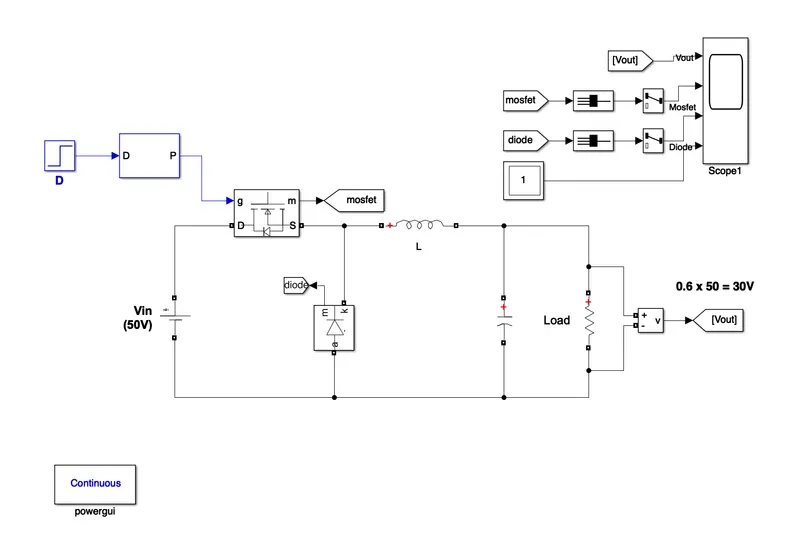
The basic operation of the buck converter has the current in an inductor controlled by two switches (usually a transistor and a diode). In the transistor is shown as a simple switch.
Given those assumptions, the conceptual model of the buck converter is best understood in terms of the relation between current and voltage of the inductor. Beginning with the switch open (off-state), the current in the circuit is zero. When the switch is first closed (on-state), the current will begin to increase, and the inductor will produce an opposing voltage across its terminals in response to the changing current. This voltage drop counteracts the voltage of the source and therefore reduces the net voltage across the load. Over time, the rate of change of current decreases, and the voltage across the inductor also then decreases, increasing the voltage at the load. During this time, the inductor stores energy in the form
Boost converter:
The boost converter is the step up DC-DC converter. The output capacitor is the one that filters the pulsating current and allows DC current to flow through the output.
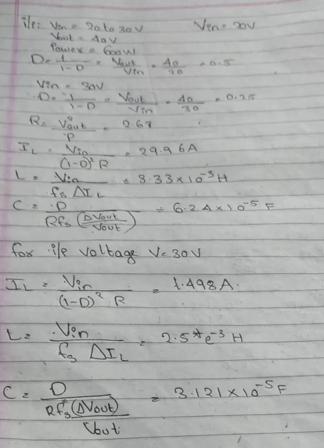
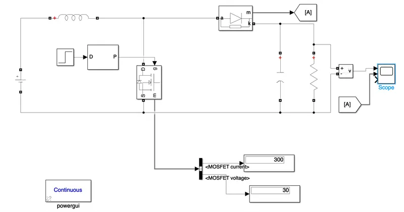
In continous conduction mode, the inductor current flows continously during the operation of the converter.The two semiconductors during the operation of the converter. The two semi conductors switches in operation are diode and Mosfet which operate with the PWM pulses. MOSFET is a switch whose gate pulses are given by the PWM pulse generator based on the duty requried to the switch.
It is considered that the frequency is considered as 30KHZ.
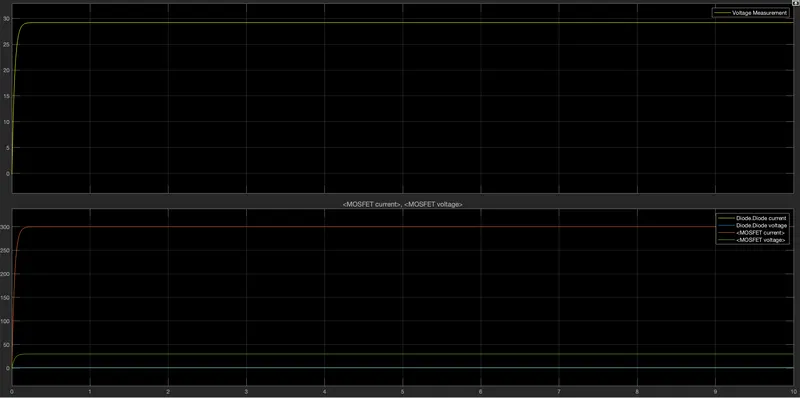
The schematic of Boost converter is as shown below.
SEPIC:
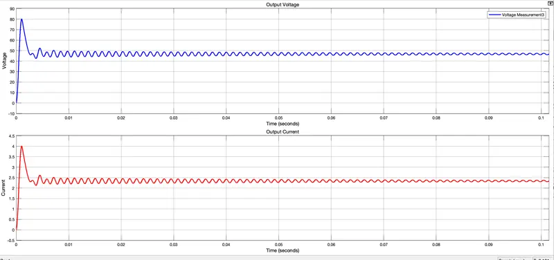
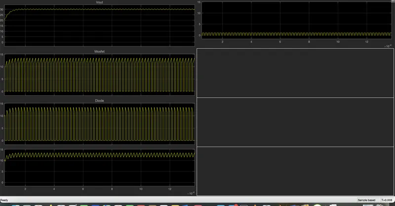
Results: