Project 1
# AIM
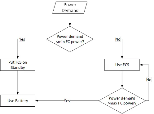
Create a Stateflow or Simulink model for the following flowchart.
Load the .mat file into the workspace.
The input to the model would be the power demand.
The output should be:
- Fuel cell power
- Battery power
- FC Operating state (running, standby)
Create plot of these outputs against time.
# THEORY
Energy storage technologies could be mainly categorized into four types: electrochemical devices (e.g., batteries, fuel cells), electrostatic devices (eg, supercapacitors), and electro-mechanical devices (e.g., flywheels), and electromagnetic devices (e.g., superconducting magnetic energy storage (SMES) systems). The energy density and power density are the two key features that could be used to characterize an energy storage system. The energy density is defined as the energy stored per-unit weight, hence energy density signifies the relative size of the storage system. The power density is defined as the amount of power that could be obtained for a per-unit weight. Figure below illustrates the power and energy density characteristics of different energy storage technologies suitable for ship microgrids.
Battery Energy Storage Systems (Lead-acid, li-ion, NiMH or NiCad)
The lead-acid, Li-ion, NiCad and NIMH are the most commonly used battery types in battery energy storage systems. However, lead-acid batteries are rarely being used in energy storage system applications mainly due to their low energy density and low power density. Similarly, NiCad batteries also have low energy density and low power density and thus rarely being used in battery energy storage systems.
The most commonly used battery technology is the Li-lon technology, which has high power density and high energy density in comparison to the other battery technologies available in the market. The Li-Ion batteries are maintenance-free and also have the highest lifetime (at 80% depth-of-discharge (DOD)) over other battery types available in the market.
Supercapacitors:
Supercapacitors (also known as ultracapacitors) have the capability to release or absorb a large amount of power instantaneously than battery energy storage systems. In supercapacitors, energy is stored in an electrostatic field and hence the charging and discharging cycles can be repeated without any limit and also it could be charged within a very short time span as opposed to batteries. The supercapacitor structure is different to a conventional capacitor due to its electrostatic double-layer and thinner carbon electrodes. These properties increase the capacitance of supercapacitors compared to the conventional capacitor.
Fuel cell
Fuel cell stores high energy because it uses fuel to produce electricity. Fuel cells work like batteries, but they do not run down or need recharging. They produce electricity and heat as long as fuel is supplied. A fuel cell consists of two electrodes-a negative electrodes (or anode) and a positive electrode (or cathode)-sandwiched around an electrolyte. A fuel, such as a hydrogen, is fed to the anode, and air is fed to the cathode. In a hydrogen fuel cell, a catalyst at the anode separates hydrogen molecules into protons and electrons, which take different paths to the cathode. The electrons go through an external circuit, creating a flow of electricity. The protons migrate through the electrolyte to the cathode, where they unite with oxygen and the electrons to produce water and heat.
As shown in the above flowchart, there are two power sources mentioned as Fuel Cell (FC) and Battery.
The logic which is been told to develop in this is that if the Power demand from the vehicle is less than the minimum FC power than the FC must go on standby and the power should be supplied from the battery storage system and if the power demand is greater than the min FC power than the FC should be used and if the power demand of vehicle is fore than the max power of FC than the Battery should supply the power.
The Simulink model is been developed for this as shown below,
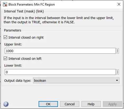
- For this, the min FC power is kept between 0 to 1000w
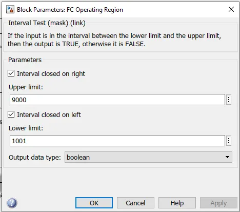
- The operating region of FC is 1001w to 9000w
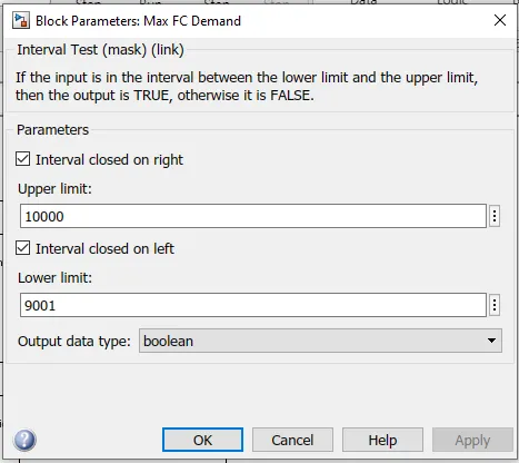
- And max power demand is set till 9001w to 10000w.
# SIMULATION
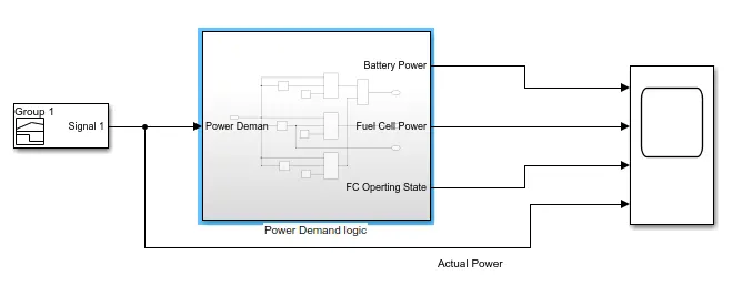
- The signal Builder block is used as the input to give the power demand required by the vehicle
- The simulation is been run for 200 sec and the output such as FC Power, Battery Power, and FC status are been studied by connecting it to the scope.
* If we look inside the logic block of the Simulink the model is as shown below:-
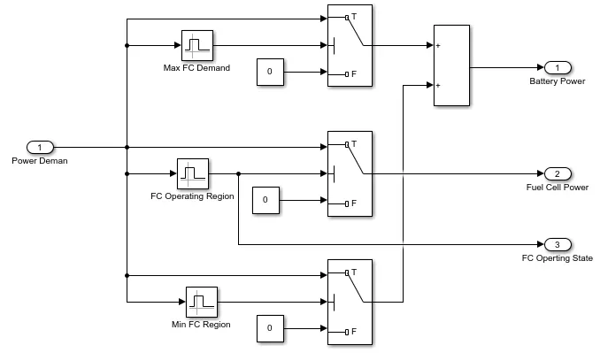
- The interval test block are used for setting the limits of the FC minimum, maximum, and operation region
- The limits are been set as discussed above. Then as per logic, the switch block is been set and the output is been connected to FC or battery as mentioned in the flowchart.
FC Operation Region Interval Test
Battery Operation Interval Test
* Signal Builder profile is as shown below:-
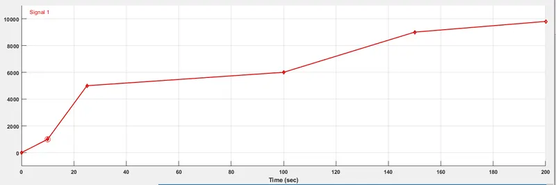
- As in signal builder for 0 to 10 sec the power demand is between 0-1000w (Battery power)
- From 10-25sec the power demand is between 1001-5000w (Fuel Cell Power)
- From 25-100sec the power demand is between 5000-6000w (Fuel Cell Power)
- From 100-150sec the power demand is between 6000-9000w (Fuel Cell Power)
- From 150-200sec the power demand is between 9000-9800w (Battery power)
- When the battery provides the power at the same time the FC should be on standby
- when the power demand is greater than min FC power then FC should be used
- If the power demand exceeds max FC power then the battery should be switched back.
# SIMULATION RESULTS
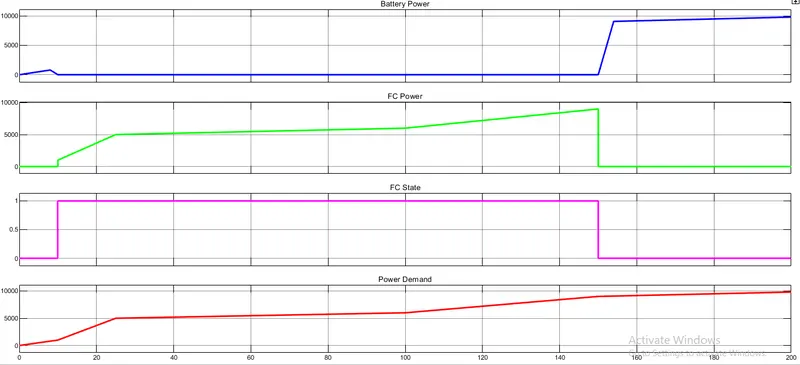
- From the graph, it's clear that When the battery provides the power then the Fuel Cell is on standby
- when the Battery is in operation, the FC status is been shown as 0.
- When the Fuel Cell provides the power then the Battery is on standby
- We can see that when the Fuel Cell is in operation, the FC status is been shown as 1.
- From the results, it's clear that the logic which is been developed is fully proven and working properly as per the logic defined.
- From 0 to 10 sec the power demand is between 0-1000w then the Battery power the vehicle
- From 10-25sec the power demand is between 1001-5000w then Fuel Cell Power the vehicle
- From 25-100sec the power demand is between 5000-6000w then Fuel Cell Power the vehicle
- From 100-150sec the power demand is between 6000-9000w then Fuel Cell Powerthe vehicle
- From 150-200sec the power demand is between 9000-9800w then the Battery power the vehicle
# CONCLUSION
Created a Simulink model with input to the model is power demand, the output is Fuel cell power, Battery power, and FC Operating state (running, standby).