Project 1
Project 1
- AIM AND OBJECTIVE OF METRO RAIL
THE OBJECTIVE IS TO PROVIDE SOCIO- ECONOMIC BENEFITS AND EQUAL OPPORTUNITIES IN PUBLIC SPACE TO ALL CITIZEN
THE TICKET PRICING IS AFFORDABLE
THE JOURNEY TIME REDUCE AND POLLUTION IS ADDRESSED BY WAY OF DESIGN.
IT IS ALSO CONVENIENT THAT YOU CAN REACH YOUR DESTINATION ON TIME AND WITHOUT ANY PROBLEM.
1. Mention the need for a metro rail in a developing economy.
- The Metro Rail System has proven to be most efficient in terms of energy consumption, space occupancy and numbers transported.
- High-capacity carriers – very high volumes of peak hour peak direction trips.
- Eco-friendly – causes no air pollution, much less sound pollution.
- Low energy consumption – 20% per passenger km in comparison to road-based systems.
- Greater traffic capacity – carries as much traffic as 7 lanes of bus traffic or 24 lanes of car traffic (either way).
- Very low ground space occupation – 2 meter width only for elevated rail.
- Faster – reduces journey time by 50% to 75%.
2. Perform longitudinal analysis of 3 x 25m prestressed I-girder for metro viaduct in STAAD by creating the nodes, beams, and supports being assigned to those nodes for a slab and girder that has been presented in the videos.
AIM OF I GIRDER IN BRIDGE OF METRO RAIL.
Girder bridge are the simplest bridge type in structure and consist of steel beams shaped to an I section
girder bridge are comprised of deck slabs on which vechicle and people pass and main girder supporting the deck.
This girder is almost used in the large construction of structure
AIM OF DECK SLAB
Transition between a roadway pavement and bridge.Road level-level of road to which the level of bridge is adjoined by the approach slabBack wall-vertical wall at the end of the bridge supporting the expansion joints & extend up from abutment seat.Wing wall-adjacent to the abutments and act as retaining walls, provided at the both end to retain soil of earth filling for approach slab.Deck slab-a slab of concrete used to make the base for the roadway, railway, pedestrian walkaway, etc. on the bridge.
ANS- I am submitting the whole solution by screenshot whatever challenges is given in it .
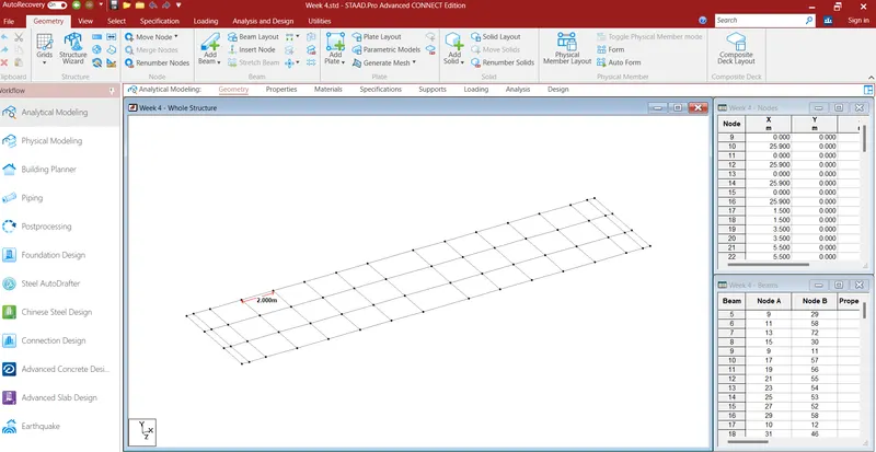
STEP 1 - CREATE THE LONGITUDINAL AND TARVERSE LINE BY PUT THE NODE VALE
IN FIG MENTION THE ALL NODE VALE .
-
STEP 2- GO TO SUPPORT AND CREATE THE SUPPORT OF BEAM STRUCTRURE
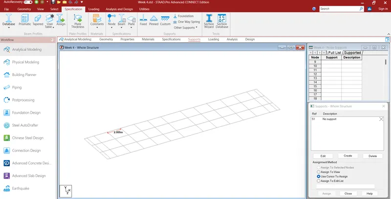
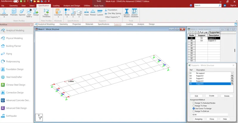
STEP 3 SUPPORT PROVIDE THE ROLLER SUPPORT TO BEAM SELECT THE BEAM ALL AND ASSIGN TO SELECTED BEAM
STEP 4 GO TO THE PROPERTY
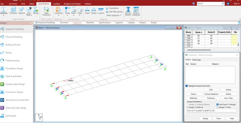
STEP 5 THEN GO DEFINE AND GO GENERAL FOR PUT THE MOMENT LOAD OF COORDINATE
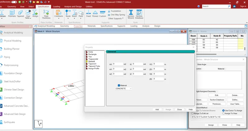
STEP 6 THEN PUT ALL VALUE Ax Ix Iy Iz
1.75808 0.1818 0.6802 0.285
1.41702 0.07 0.625 0.26
1.59 0.126 0.652 0.272
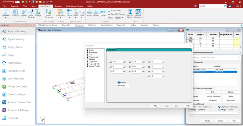
STEP 7 GO DEFINE AND CLICK ON RECTANGLE AND CREATE THE THICKNESS OF BEAM DUMMY
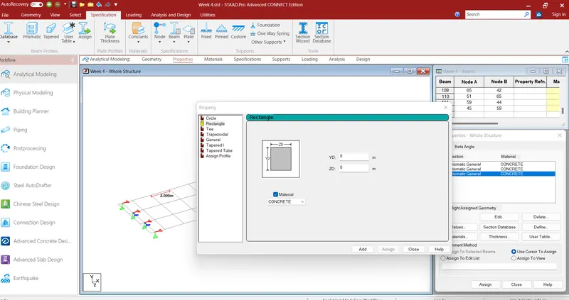
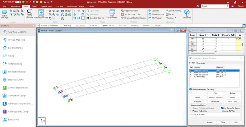
STEP 8 CREATE ALL SECTION BEAM WITH MATERIAL
STEP- 9 CLICK ON LOADING AND GO TO VECHICLE DEFINITION AND PUT THE LOAD AND DIST
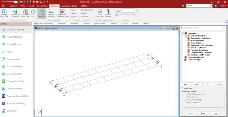
STEP 10 GO TO LOAD CASE DETAILE
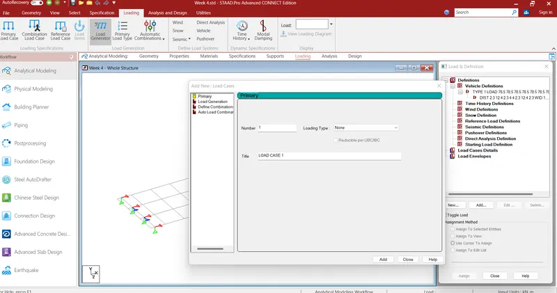
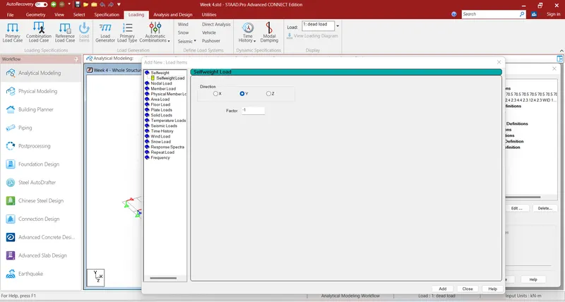
STEP 11 IN DEAD LOAD FOR SELFWEIGHT PUT -1 IN GOLOBAL Y DIRECTION
STEP 12 GO TO SIDL LOAD AND CLICK ADD THEN GO TO MEMEBER LOAD AND CLICK UNIFORM
FOR FIND DIRECTION OF LOAD IN GOLOBAL DIRECTION DEAD LOAD SIDL LOAD ETC.
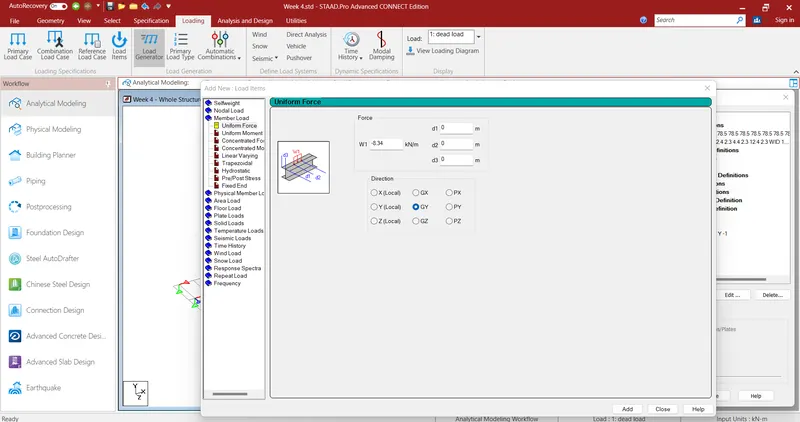
STEP 13 APPLIED ALL LOAD ON BEAM LIKE SIDL DEAD LOAD .

STEP 14 AFTER LOAD APPLIED THIS ISOMETRIC VIEW I GIRDER
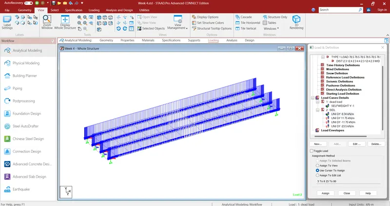
STEP 15 LOAD APPLIED UNIFORM -23.5 OF I GIRDER THIS VIEW
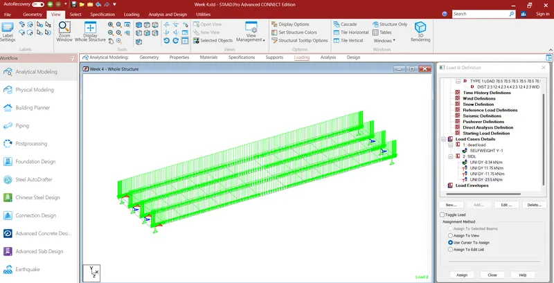
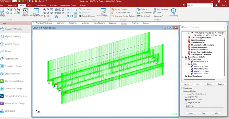
STEP 16 LOAD APPLIED ON I GIRDER VERTICAL OF THIS VIEW
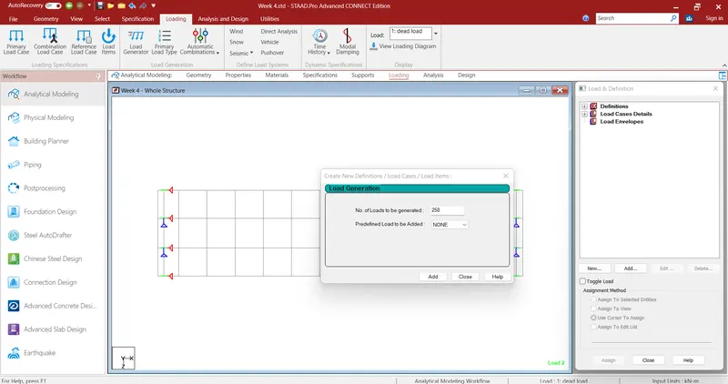
STEP 17 GO TO LOADING AND CLICK LOAD GENERATION AND PUT THE LOAD VALUE AFTER FIND THE METRO VIADUCT
STEP 18 GO ANALYSIS AND DESIGN AND CLICK ON RUN ANALYSIS
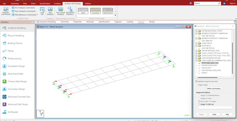
STEP 19 THEN GO TO POSTPROCESSING AND CLICK ON APPLY THEN CLICK OK FOR CHEAK LOAD
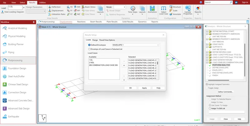
STEP 20 AFTER THIS VIEW IN THIS WE KNOW MAXIMAM AND MINIMUM LOAD WHERE
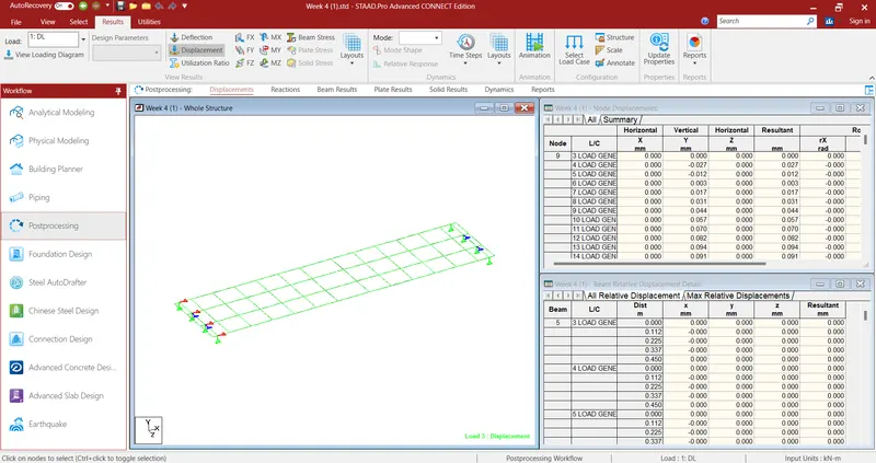
STEP 21 IN THIS VIEW AFTER ALL LOAD APPLIED WE THE BENDING MOMENT OF THIS STRUCTURE
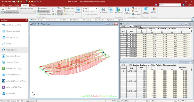
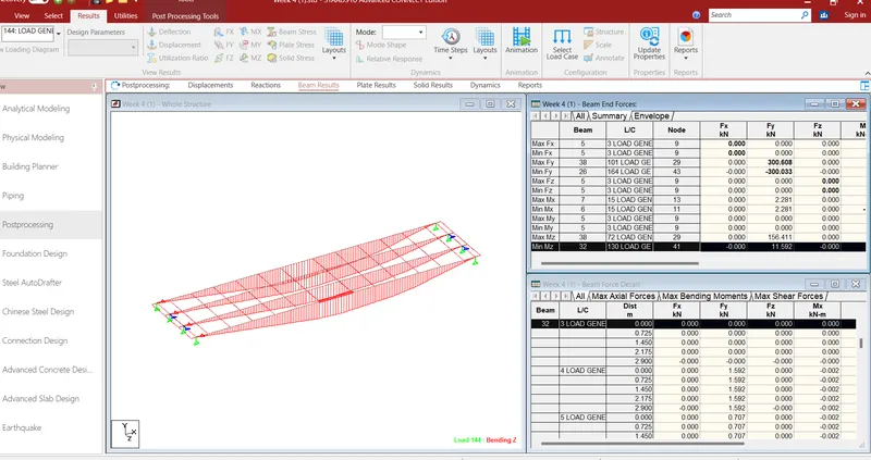
STEP 22 GO TO SUMMARY AND CLICK SELECT LOAD AND THEN GO TO LOAD GENERATION AND CHEAK WHERE
SIDL AND DEAD LOAD MAXIMUM AND MINIMUM
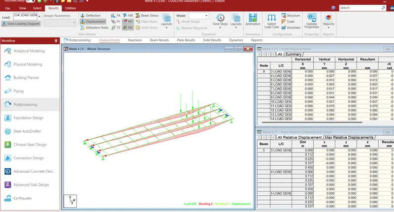
STEP23 CHEAK MAXIMUM AND MINIMUM LOAD APPLIED WHICH NUMBER OF BEAM CHEAK
3. Prepare a transverse STAAD model of U-girder with the following specifications:
- Finite element model of U-girder with a span length of 30m.
- Having supports at 0.7m from both ends.
- Having the following geometrical properties:
- Thickness of bottom slab – 300mm
- Thickness of top web (both sides) – 240mm
- Thickness of slant web - varying from 300mm to 240mm
- Concrete grade M55.
- Reference inputs can be taken from the relevant video sessions if needed.
SOLUTION- THIS PROCEDURE IS DOING BY STAAD SOFTWARE
STEP1- NODE VALUE PUT.
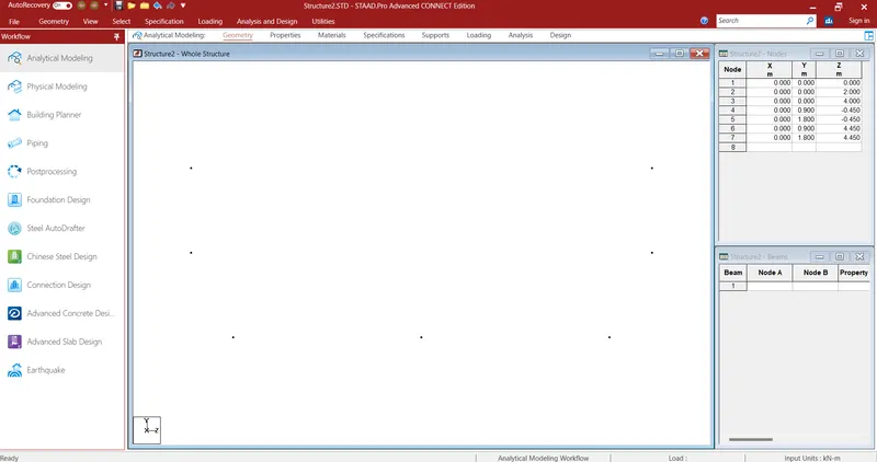
STEP 2 AFTER PUTING NODE VALUE
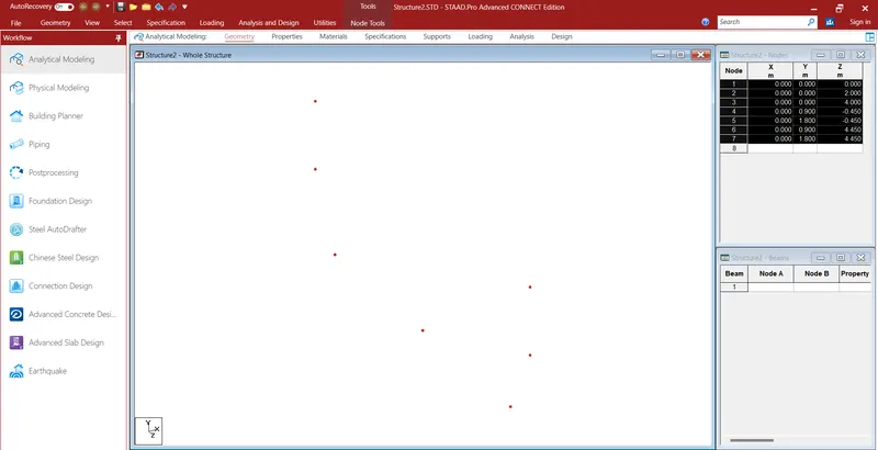
STEP 3 GO TO GEOMETRY
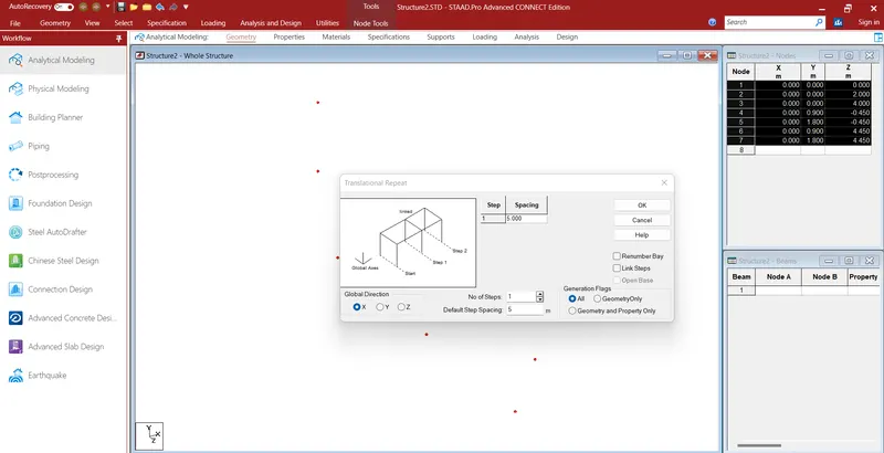
STEP 4 IN STEP SET THE SAPACING OF NODE
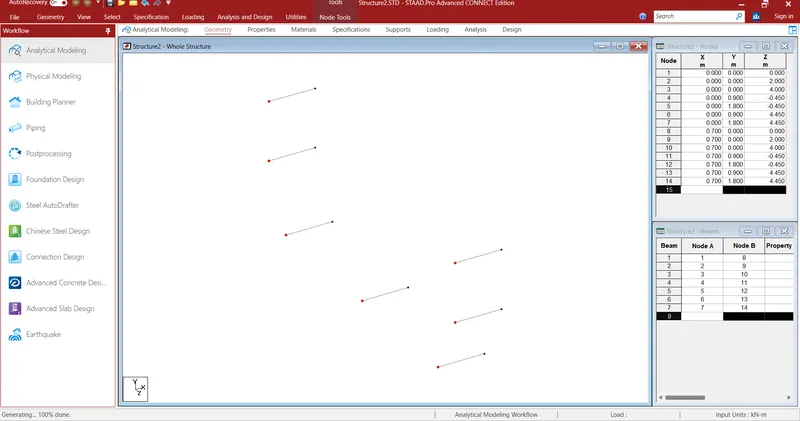
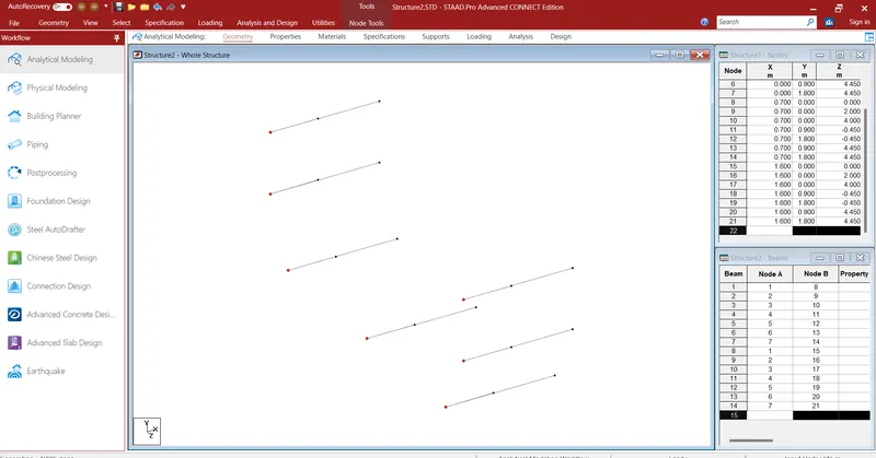
STEP5 CONNECT THE NODE TOGETHER
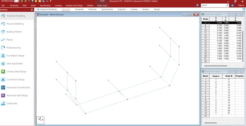
STEP 6 CLICK ON ISOMETRIC VIEW
STEP 7 GO TO PLATE CURSIER
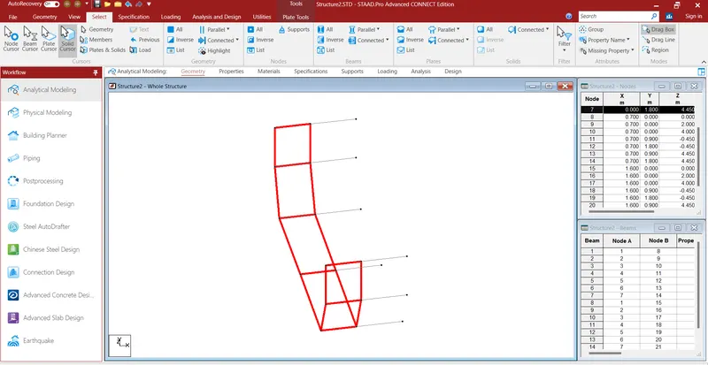
STEP 8 ALL NODE CONNECT AFTER THIS VIEW
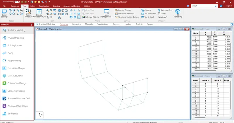
STEP 9 GO TO TOP VIEW
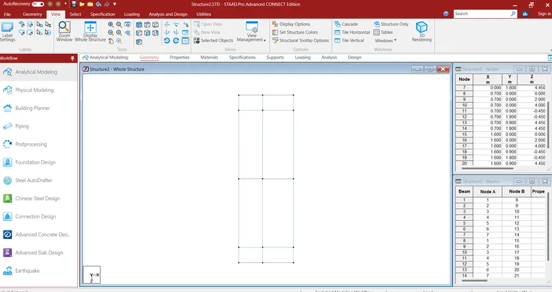
STEP 10 SLECT PLATE CURSIER
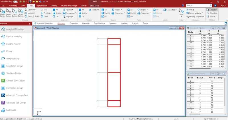
STEP 11 GO GEOMETRY
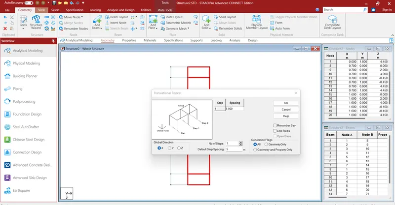
STEP12 THIS VIEW IS TOP
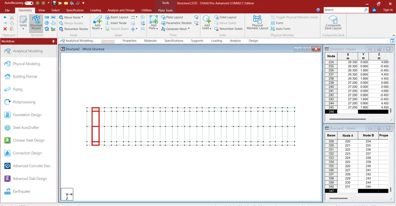
STEP 13
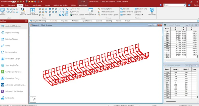
STEP 14 MAKE BEAM
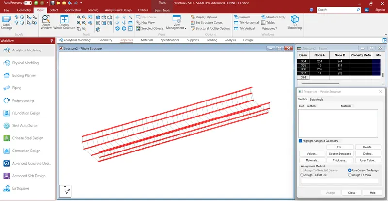
STEP 15 CHEAK THICKNESS
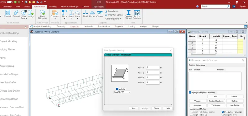
STEP 16 AFTER THE PUTING THIKNESS CLICK ISOMETRIC VIEW
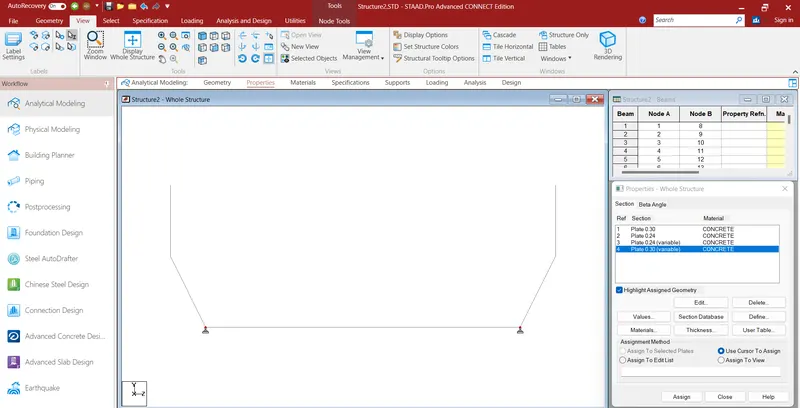
STEP 17 ASSIGN THE PLATE
17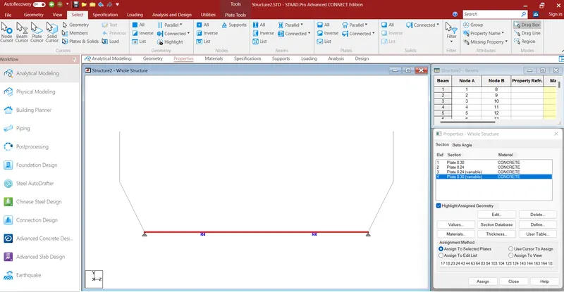
STEP 18
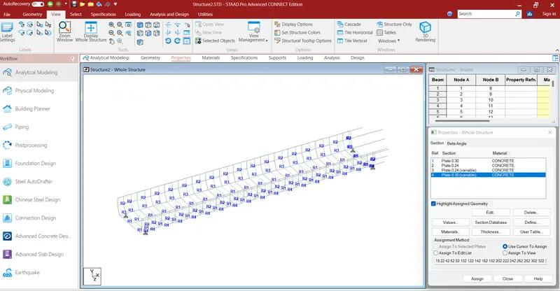
STEP 19 ASSIGN THE CONCTRETE
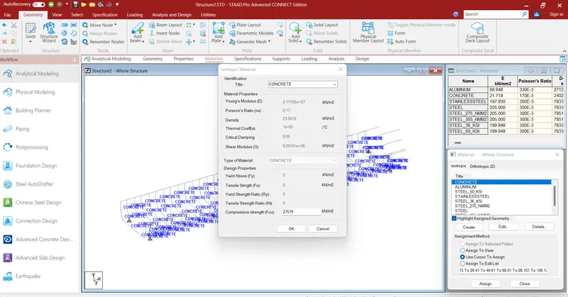
STEP20 LOADING VIEW
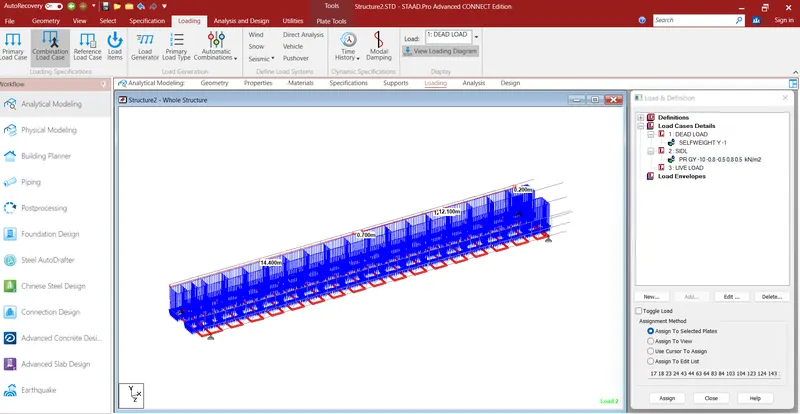
STEP 21 LOADING PART POINT
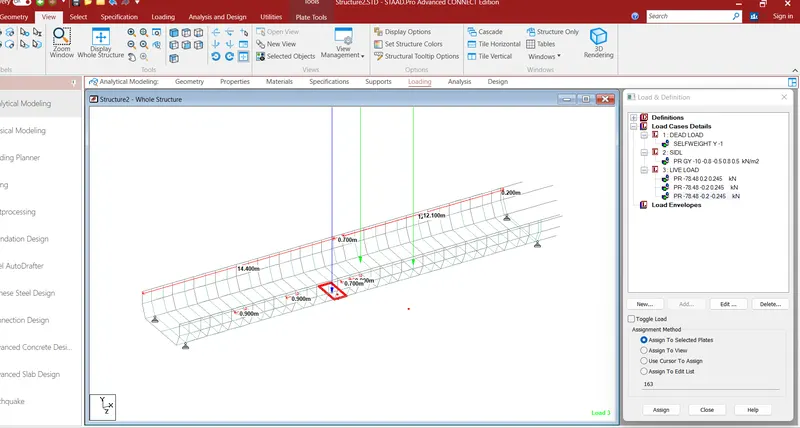
NOW ANSWER IS OVER.I FALLOW ALL STEP THAT IS AVAILVAL IN LECTURE .
4. For a prestressed U girder, calculate the following with the given data,
- Area = 2.1735m2
- I = 0.74035m4
- Calculate Prestressing force considering 76.5% jacking stress with 72 no. of strands.
- Calculate Section Modulus of U-girder considering ybot = 0.594m
- Calculate eccentricity of Prestress tendons from CG of section considering ybot = 0.594m and cg of PT cables = 0.140m from soffit level.
- Calculate Stress at bottom of U-girder considering M=10628.58kN-m and details mentioned previously.
ans - Elastic shortening fy=mfc
where fy= drop in prestress
m= modular ratio
fc= stress in concrete
In a girder creep loss and shrinkage loss anchorage loss etc.
creep loss = fp=Ep ecr, ult
shrinkage loss=Fp=Ep esh
where
fp= loss in prestress
Ep= modulos of prestressing steel
Ecr,ult= ultimate creep strain
Esh=ultimate shrinkage strain
no of strands used (n)= 72
prestressing force applied=p
0.765fpu*As*n*(1-loss)/1000 kn
=(1422.9*140*72*82.5%)/1000kn= 11832.8 kn
sectional modulus(Z)=I/Y
for cheaking stress at bottom
Ybot=0.594m
Z=(0.74035/0.594 metre cube=1.2464
stress at bottom= p/a+P*e/z-m/z
(11832.8/2.1735)+11832.8*0.494/1.2464)-10628.58/1.2464)
= 544.12+4689.83-8527.42 kn/metre square= 1.607 N/mm square