Project 1
The selected three topologies are
1) Buck converter in Continuous Conduction Mode(CCM)
2) Boost converter in Continuous Conduction Mode(CCM)
3) Inverting Buck-Boost converter in Continuous Conduction Mode(CCM)
Design

------------------------------------------------------------------------------------------------------------------
Simulation
BUCK CONVERTER
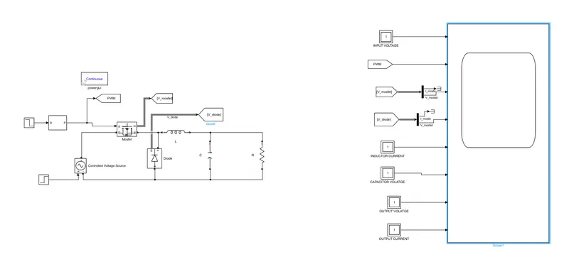
As the input voltage is varying the step function is used to vary the input from 40 V to 50 V at t=0.0025 sec
Duty ratio D= 0.75 to 0.6 at t=0.0025 sec and generating accordingly the pulses to turn ON and OFF the MOSFET and thus to maintain the output voltage constant at Vo=30 V.
Results:
1.Output voltage and current waveforms:
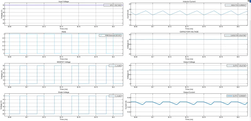
- From the above waveforms we can see the output voltage almost 30 V , And at t=0.0025 sec we can observe small overshoot during transient and settles down in the steadystate.
- At t=2.5 msec , the input voltage is varied from 40 to 50 V. Here, the input current is pulsating DC waveform.
- According to design requirement the inductor current ripple is maitained below 25% of Average inductor current and it is in Continuous conduction mode(CCM).
- From the above waveforms we can observe that the maximum breakdown voltage of devices.
----------------------------------------------------------------------------------------------------------------------------------------------------------------
BOOST CONVERTER
ZOOMED IN
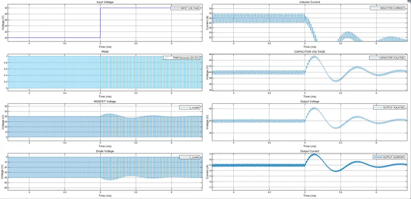
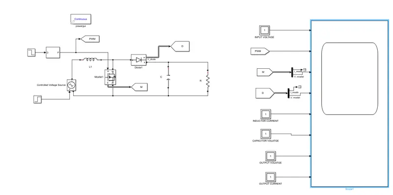
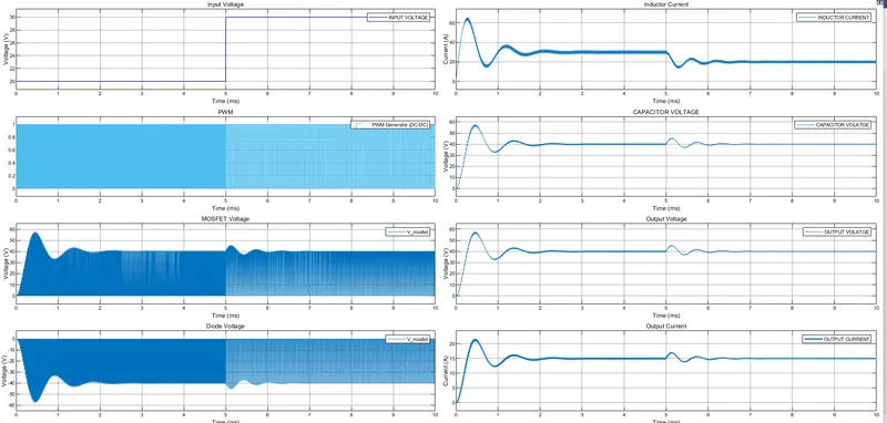
- From the above , the output voltage is almost 40 V , at t=5 msec we can observe small overshoot during transient and settles down in the steadystate.
- At t=5 msec , the input voltage is varied from 20 to 30 V.
- According to design requirement the inductor current ripple is maitained below 25% of Average inductor current and it is in Continuous conduction mode(CCM).
- Here, the devices breakdown voltages are same and it doesnot depend on the duty ratio, it depends on the output voltage i.e., 40 V.
----------------------------------------------------------------------------------------------------------------------------------------------------------
BUCK BOOST
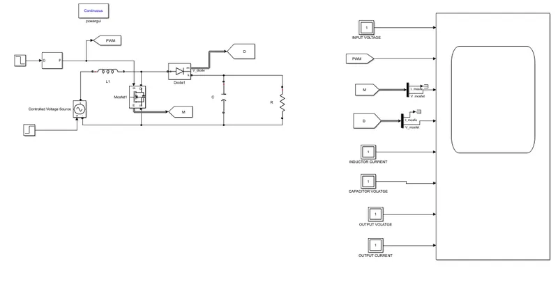
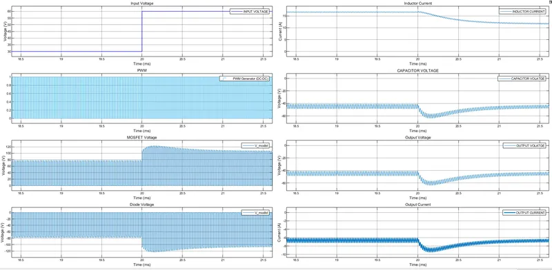
- The output voltage almost -45 V . At t=20 msec we can observe small overshoot during transient and settles down in the steadystate.
- At t=20 msec , the input voltage is varied from 30 to 60 V.Here, the input current is pulsating DC waveform. Hence, to make input a pure DC value we need to add the input filter.
- According to design requirement the inductor current ripple is maitained below 10% of Average inductor current and it is in Continuous conduction mode(CCM).
- with variation also, the output is almost constant with very small variation