Project 1
Aim and Introduction:-
- The aim of this challenge is to determine the impact on the structure due to application of loads like dead loads, live load due to metro train ,earth pressure load, wind load and seismic load for the bridge structure at Ahmedabad and to calculate the effect of the loads on the structure as various forces like shear force, bending moment etc using staad Pro.
- So first of all the details components for calculating the magnitude of the load as per the given data is to be determined with reference to the concern IRC codes.
- Then the model will be analyzed in Staad pro., load is applied on the the structure as different load cases and the reactions, stresses and bending moments due to the loading is being analyzed for the structure as given.
Data Given:-
- Unit wt. of the soil - 18KN/m3
- Location of bridge - Ahmedabad
The Cross-Sections of the metro project

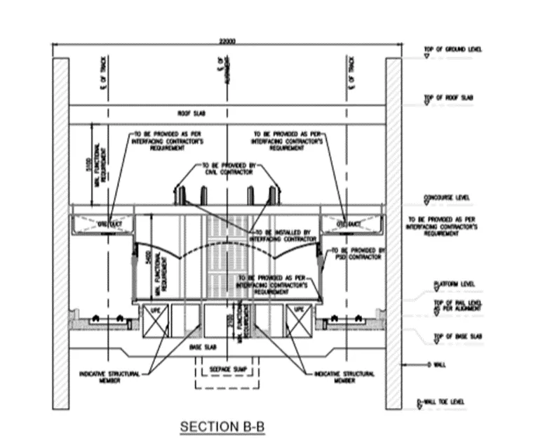
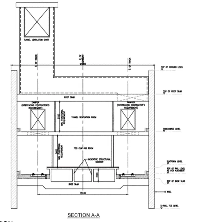
STAAD Model-
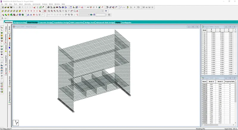
- The model of the metro rail project.
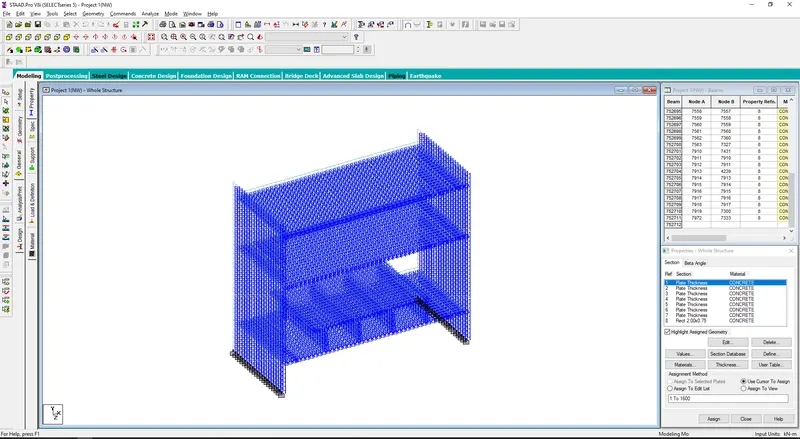
- The properties for different sections for the structure is defined for the structure.
Load & Definations:-
- Seismic Load-
Seismic Force = Ah x W
Where, Ah = design horizontal co-ifficient
W = Seismic weight of the building
- The seismic criteria as given is defined and the details has been generated in the STAAD model.
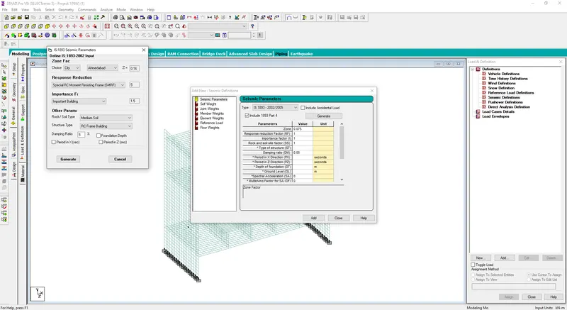
- In this metro rail project the seismic force will be acted only in X direction in +ve x and -ve x direction.
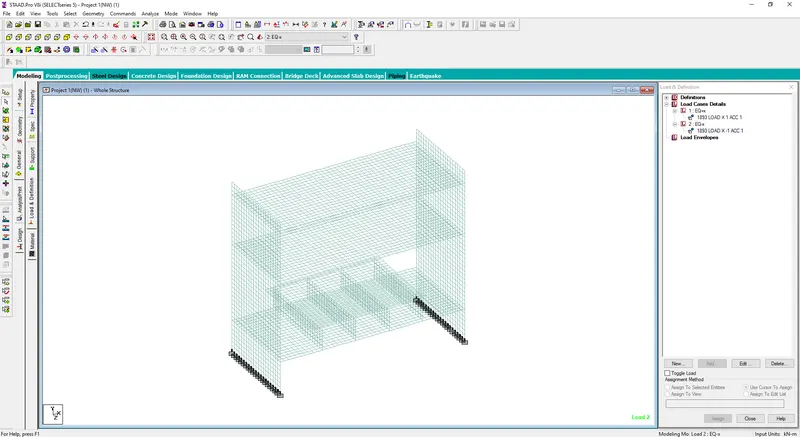
- The seismic for in both the direction in X has been assigned.
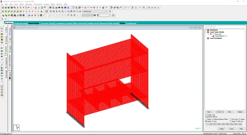
- Dead Load -The structure is a underground structure with two storey. The structure is made up of concrete. So the dead load for the whole structure is applied to the structure in the model.
- Live Load- The IRS loading for the metro rail is to be applied on the track of the model. The load with configuration for the metro train has been defined.
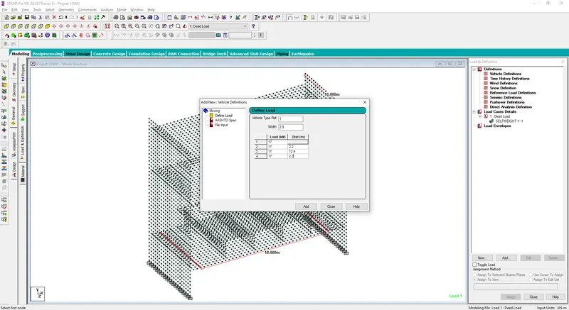
- The load cases has been generated for two trains in both the tracks for the metro bridge project.
- Wind Load- The wind load doesn't affect the structure as it is a underground project. So the application of wind load is not required for this structure.
- Earth Pressure Load-
Length of Wall =10 m (as per the given Section)
Ht. of back fill = 20m
GL. Level = 20m
Water Level at = 3m
Wall Width =0.75 m
Unit Wt. of Soil = 18 KN/m3
Unit Wt. of Concrete = 25 KN/m3
Consider ϕ = 30
Active earth pressure
Constant = Ka = (1-Sinϕ)/ (1+Sinϕ)
= (1-Sin30)/ (1+Sin30)
= 1/3
i.e., Active Earth Pressure = Ka x γ x H
= 1/3 x 18 x 20
= 120 KN/m2
Passive earth pressure
Constant = Kp = (1+Sinϕ)/ (1-Sinϕ)
= (1+Sin30)/ (1-Sin30)
= 3
i.e., Passive Earth Pressure = Kp x γ x H
= 3 x 18 x 20
= 1080 KN/m2
Considering the backfill soil acts as active earth pressure.
- The earth pressure for the wall of the project has been defined as per the calculated data and has been assigned in the model.
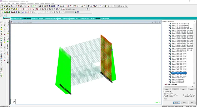
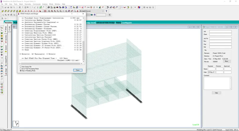
All the type of loading that has been applied on the structure as given. The analysis after applying all the kinds of load has been resulted with 0 error.
Results:-
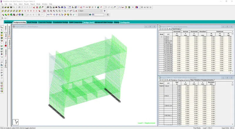
- Deflection due to seismic force in x-direction
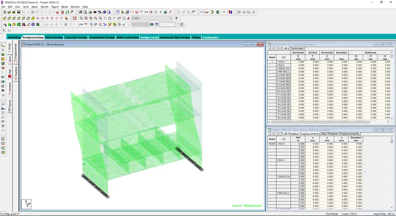
- Deflection due to seismic force in -ve x-direction
- Deflection of the structure due to application of dead load.
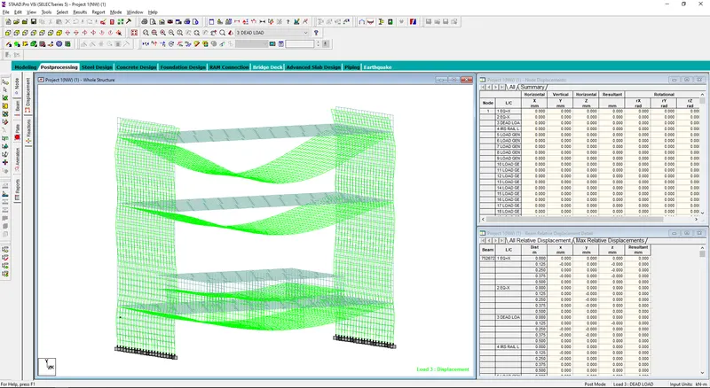
- Deflection due to application of earth pressure load on the structure.
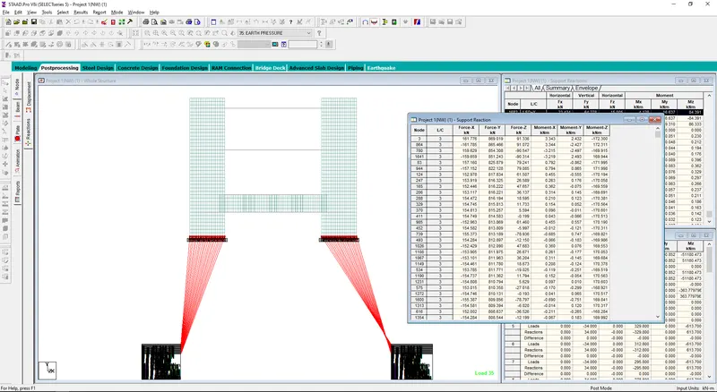
- The maximum vertical force among all the type of forces is due to the application of dead load and the magnitude of the forces has been given i.e. 869.019 KN.
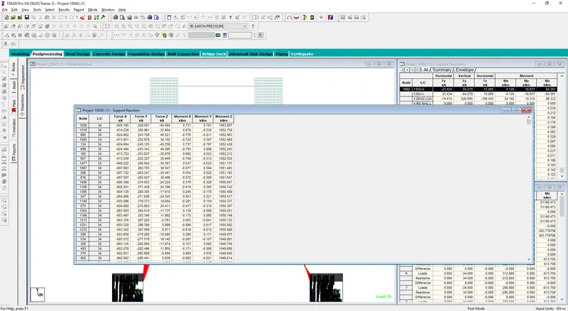
- The maximum moment in Z direction has been generated by the report in the structure.
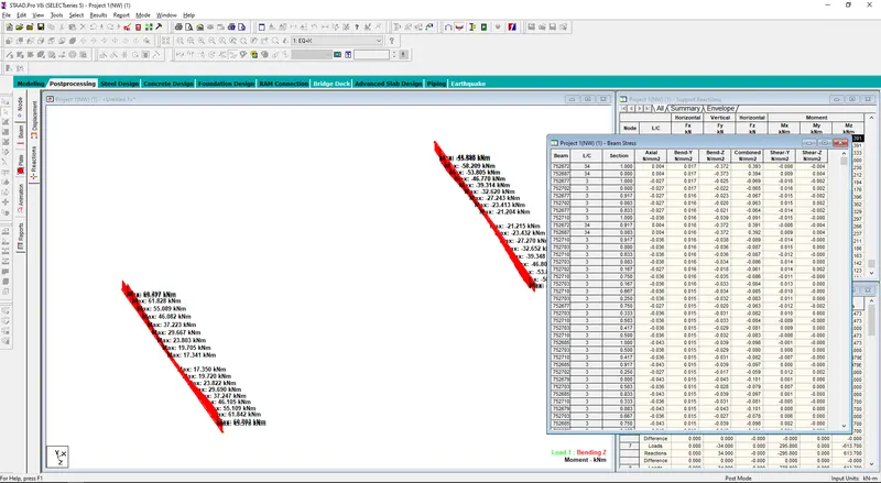
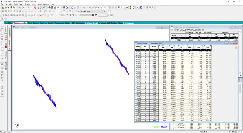
- The maximum stress in the beams of rail track has been generated and it is concluded that the maximum stress on the beams is coming due to the load case no-34.
- The maximum shear force in Y direction in the beams of rail track has been generated and it is concluded that the maximum force in y direction on the beams is coming due to the load case no-34.
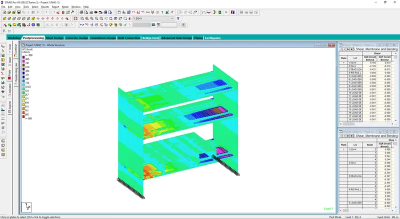
- The plate stress due to seismic load in X direction.
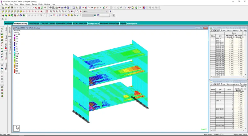
- The plate stress due to seismic load in -ve X direction.
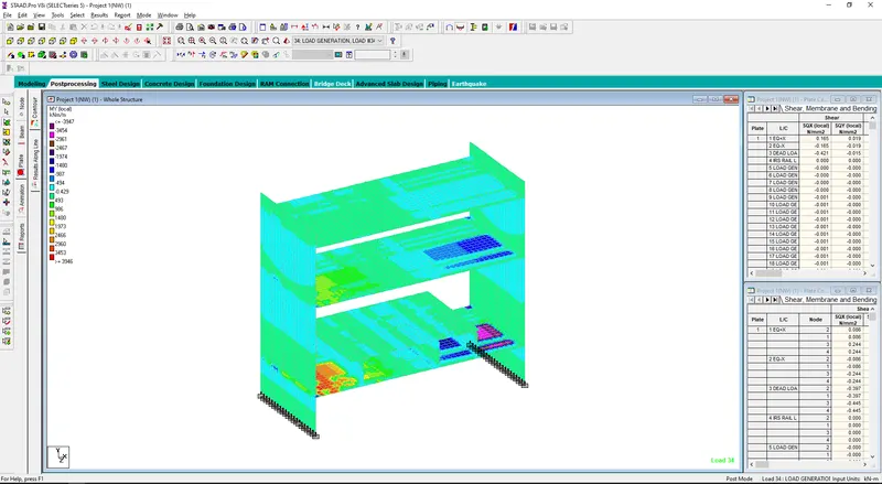
- The plate stress due to IRS load case no 34.
- The Plate stress due to earth pressure on the side walls of the structure.
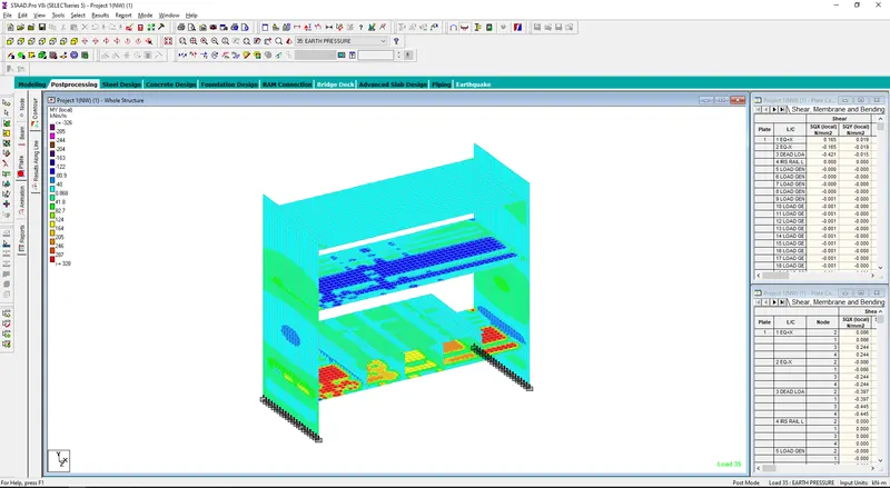
- The absolute maximum plate stress in the structure.
The reports for the maximum or minimum bending moment, shear forces or axial load stresses can be generated by generating the report from the Staad Pro. model for diffrent load cases.