Project 1
Mold Design for Table Fan Base
1. The first step is to look for tooling direction, do draft analysis along tooling direction, and look for undercuts so that we decide where to use sliders.
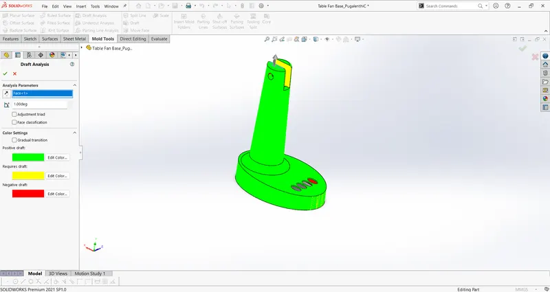
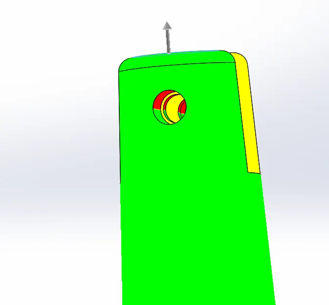
As these undercuts in the hole cannot be cleared along the tooling direction, we need sliders on both sides. And the draft on the yellow regions has to be improved for better ejection.
Scale the geometry for compensate the shrinkage of the material, shrinkage of the material in this case is 0.6%.
2. To determine the parting surface, along with which the core and cavity split.
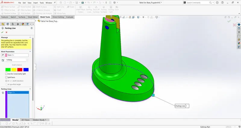
As the value of the draft changes from positive to negative along this line and hence it is the right edge for the parting line.
3. The parting surface is flat and trimmed with the parting line.
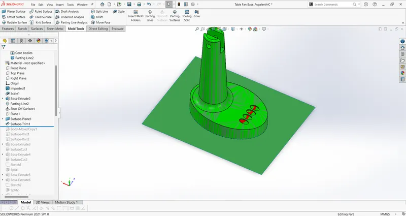
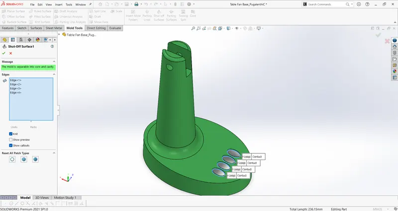
4. Shut off surfaces, as there are cuts between core and cavity sides these holes need to be closed with shut off surfaces considering the draft analysis.
shut off surfaces come along the core side considering the draft analysis along the tooling direction.
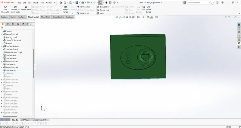
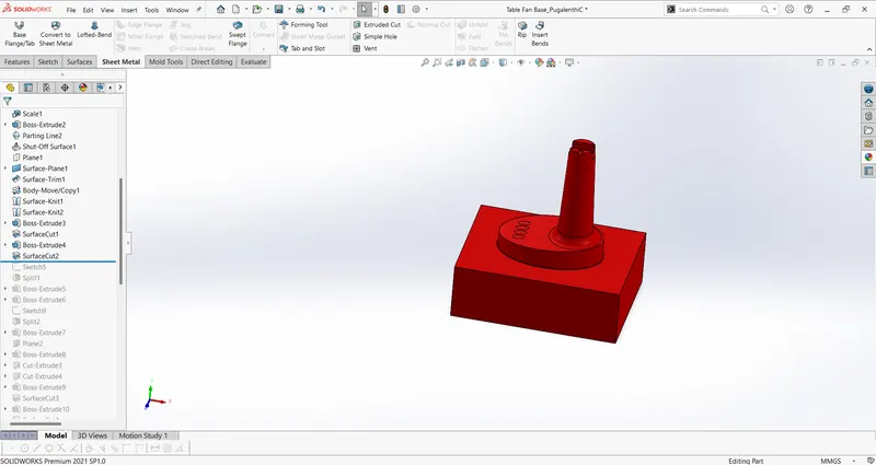
5. Core and cavity side surfaces:
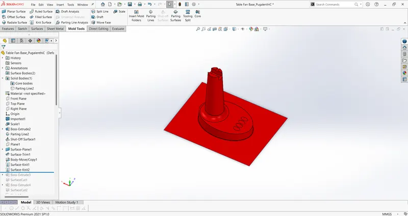
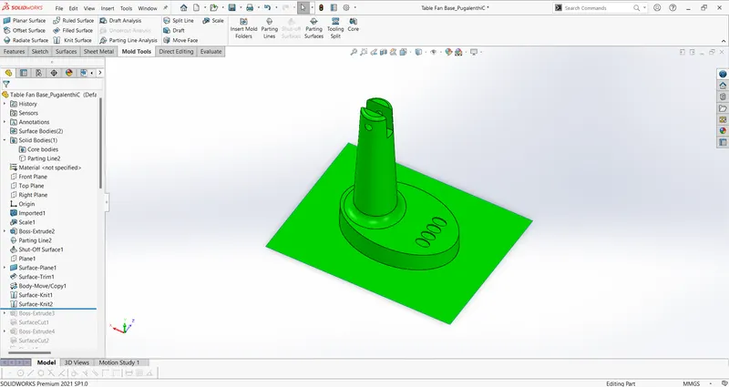
Creating core and cavity blocks:
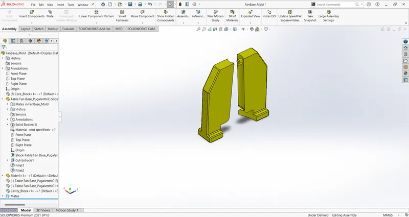
Slider creation:
Holding Mechanism for slider:
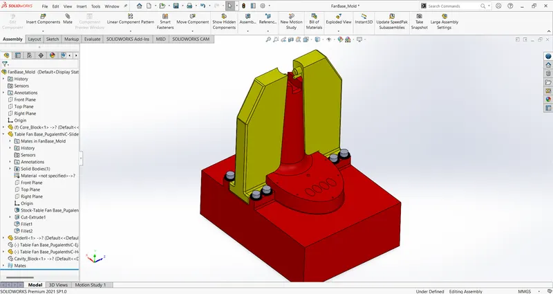
Locking Mechanism:
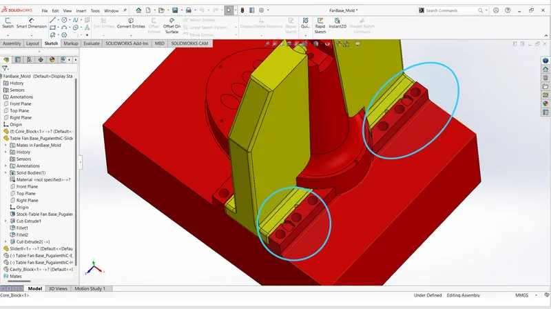
The slider has to travel atmost of 20mm to get out from the part so the locking mechanism is designed for 25mm.
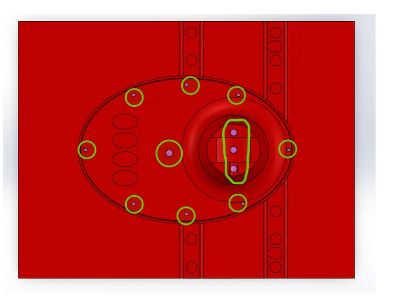
Ejector Pins:
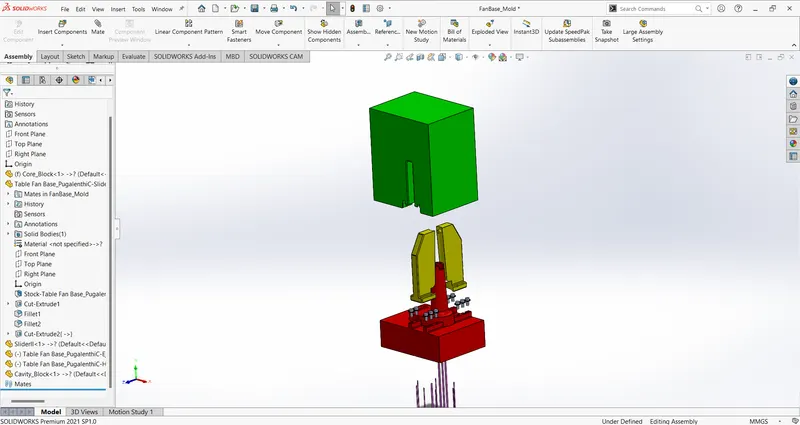
Complete assembly in exploded view: