Project 1
AIM & INTRODUCTION :- Main frame with Lean (Grid-2) & Gable frame without Lean (Grid-15) of Proposed Coil center is to be modeled and designed with given inputs-
Given Inputs- Building Width = 30 m out to out of steel
Building Length = 140 m c/c of column
Roof Slope = 1 in 10
Cear ht of Bldg = 11.10 m ( from FFL)
Bay spacing = 10 m
Column Base = Fixed
Dead Load = 0.14 KN/sqm
Live Load = 0.75 KN/sqm
Colateral Load = 0.15 KN/sqm
Purlin Load = 8.77 Kg/m = 0.0877 KN/m
PROCEDURE IN DETAIL:-
Model is prepared with given Inputs as print screen is attached below-
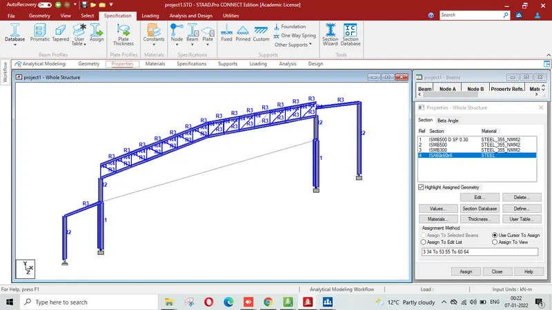
Calculation of Dead load on rafter & column= 0.14 KN/m2
= 0.14x10 =1.4 KN/m
Purlin Load = 8.77Kg/m = 87.7 N/m
= 87.7x10 N = 877 N
= 0.877 KN
Assuming Wt of Roof Sheeting (0.55 mm Galvanized sheet)
= 5 Kg/m2 = 0.05x10 =0.5 KN/m
Assuming wt of sag rod, Bracings, Clips etc. =5.75 Kg/m2=0.0575x10=0.575 KN/m
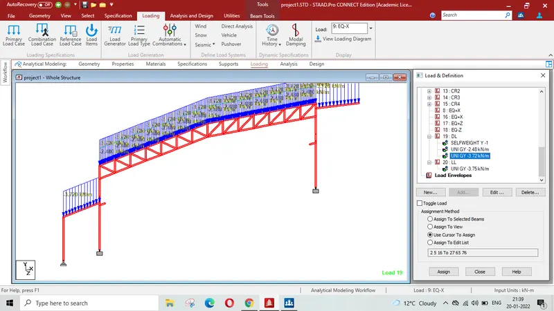
Total Dead Load = 1.4+0.5+ 0.575 = 2.475 KN/m
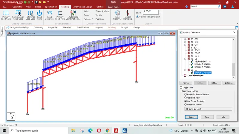
Live Load = 0.75 KN/m2x 10 = 7.5 KN/m
Colateral Load 0.15 KN/m2 x 10 = 1.5 KN/m
Total Dead Load on Lean to= 2.475/2+ 1.5 KN/m = 2.736 KN/m
( As bay spacing=5 m & colateral load 1.5 KN/m)
Live Load on Lean to = 3.75 KN/m ( As bay spacing=5 m)
Steps of Seismic Loading-
In the Loadong option we choose-------Seismic defination then defining Seismic parameters as follows- First selecting IS 1893-2002/2005
For Chennai , zone factor (Z) = 0.16 for zone-3
Response Reduction factorReduction factor =5 for SMRF ;
Importance factor =1 ( For general Building) ;
Soil type =2 ( Cosidering soil as medium soil)
Structure type =1 ; Damping Ratio =0.05
Click on Genrate Button, all parameters are available in print screen attached below-
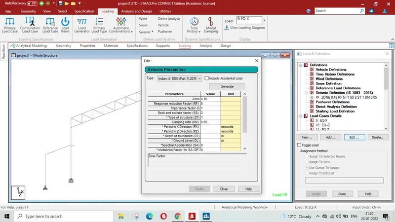
Dead load and live load as per IS 1893
Dead load is applied 100%
Live load 50% in case it is more than 3 KN
Live load on roof is considered as 0 ( In oue case 50% of LL is applied as a conservative approach as ther building is not divided inti various satory
Few print screens of seismic loading are attached below-
CRANE LOAD-
Crane capacity : 30 MT ( EOT Creane)
c/c of crane rail : 27.41 m
Crane height : 7.5 m
Crane wt including hoist : 35 MT
Gantary Girder wt : 158.24 Kg/m
Rail wt : 53 Kg/m
No of Wheels : 4
Wheel Base : 5.8 m
Bumper Distance : 6.2 m
Maximum wheel Load : 262.00 KN
Vertical impact : 25% As per IS 875
Lateral impact : 20% As per IS 875
Longitudinal impact : 10% As per IS 875
Max. wheel load ( Vertical) = [ 35/2 + 30]/2 =23.75 MT = 237.5 KN
Dead load of Rail and Gantry Girder = (158.24 + 53 )Kg/m =211.24 Kg/m
= 2.11 KN/m = 2.112x10 = 21.12 KN
Vertical load on each Bracket = 10.56 KN
Max Reaction on Crane Bracket `R_max` with Dead load of Rail & Gantry girder
= 237.5+ 10.56 = 248.06 KN
Min. Reaction on the Bracket `R_min`= 0.4x 248.06= 99 KN
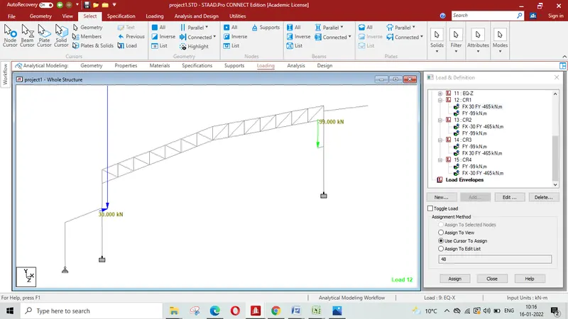
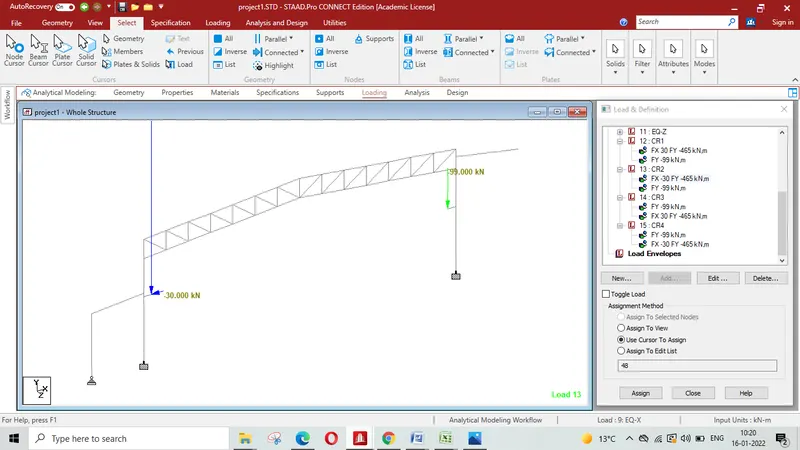
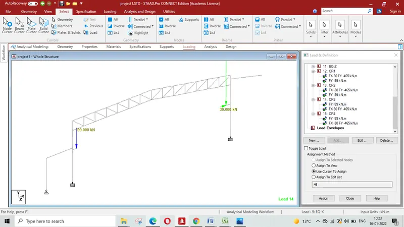
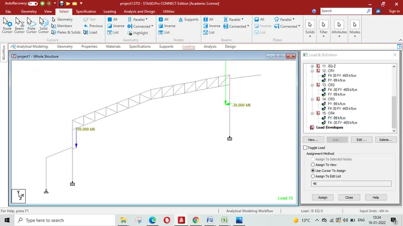
Horizontal wheel load transverse to rails = 0.2x30/2 = 3 MT = 30 KN
( 20% As per give n input but as per IS 875 PART2 Clause 6.3.2 it is 10%)
Max Reaction on the Bracket with Impact of 25% as per IS 875/ Part-2,clause 6.3
`R_max` = 1.25x 248.06 KN = 310.075 KN
Design vertical load with F.S = 310.075x 1.5 = 465 KN
`R_min`= 99 KN
Total cases-
1) `R_max` on left Bracket , +H on Left Bracket , `R_min`on Right Bracket
2) `R_max` on left Bracket , -H on Left , `R_min`on Right Bracket
3) `R_min` on left Bracket, +H on Right Bracket , `R_max`on Right Bracket
4 ) `R_min` on left Bracket, -H on Right Bracket , `R_max`on Right Bracket
Print Screen of all the above cases are shown below-
case-1 (CR1)
case-2 ( CR2)
case-3( CR3)
case-3 (CR4)
Horizontal traction force along the rails = 0.1 (262.5+262.5) = 52.5 KN
( 10% As per give n input but as per IS 875 PART2 Clause 6.3.2 it is 5%)
CALCULATION OF WIND PRESSURE:-
Basic wind speed`V_b`=180 KMPH = 50 m/s
`K_1`= 1.0 ( General Bldg as per Table-1 of IS:875,Part-3)
`K_2`=0.94 ( For Terrain category 3)
``K_3`= 1.00`( Upwind slope is less than 3 degree`)
``K_4`=1.15` ( IS 875 Cyclone Zone)
Design wind speed `V_z`= `K_1xxK_2xxK_3xxK_4xxV_b`
= 1x0.94x1.0x1.15x50 = 51.75 m/s
Wind Pressure `P_z`= 0.6x `V_z^2` = 1606.84 N/sqm = 1.61 KN/sqm
Design wnd pressure `P_d= K_d xxK_axxK_c xxP_z`
`K_d`=0.9 ( Directionality factor)
`K_a`= 0.9 ( Area averaging factor)
`K_c`= 0.9 (Roof is subjected to pressure & suction)
`P_d`= 0.9x0.9x0.9x 1.61 = 1.17 KN/sq`
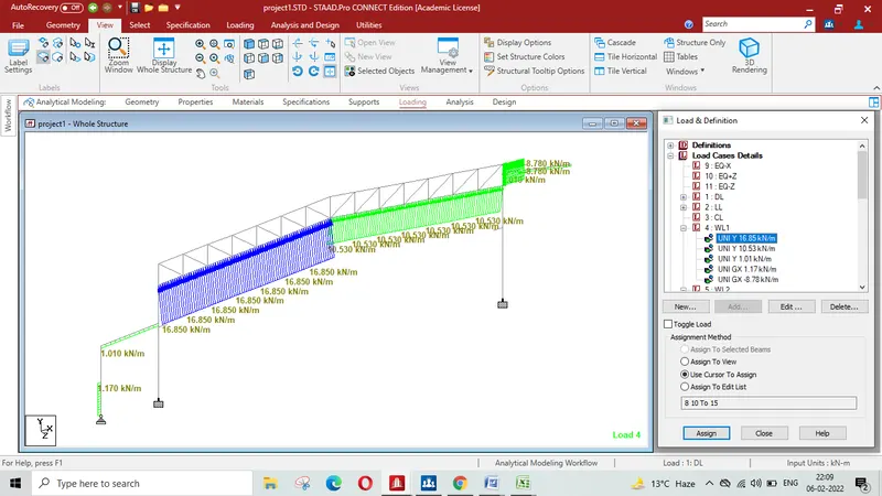
WIND LOAD CASE-1 : wind across the Ride ( 0 degree) with +v e `C_(p i)`
Roof angle `alpha = 5.71^0`
| Surface | `C_(pe)` | `C_(p i)` | `C_p=( C_(pe-C_(p i) ))` | wind load on frame`F = C_pxxAxxP_d` |
| A | 0.7 | 0.5 | 0.2 | 1.17 |
| EF | -0.94 | 0.5 | -1.44 | -16.85 |
| GH | -0.4 | 0.5 | -0.9 | -10.53 |
| B | -0.25 | 0.5 | -0.75 | -8.78 |
| C | -0.6 | 0.5 | -1.1 | -3.2175 |
| D | -0.6 | 0.5 | -1.1 | -22.5225 |
| 0.41 | 0.5 | -0.09 | -0.5 | |
| Lean to | 0.41 | 0.5 | -0.09 | -0.5 |
NOTE- `C_(pe)` for EF & GH are found by Interpolation
| `alpha` in Degree` | EF | GH |
| 5 | -0.9 | 0.4 |
| 10 | -1.2 | 0.4 |
Print screen of Load case-1
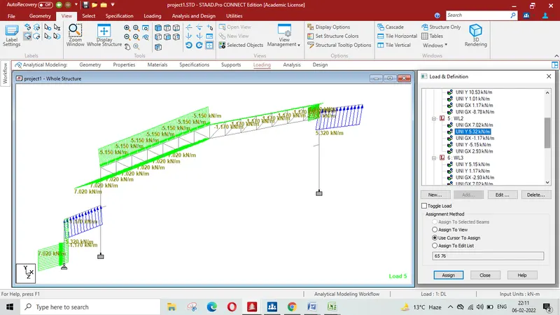
WIND LOAD CASE-2 : wind across the Ride ( 0 degree) with -v e `C_(p i)`
Roof angle `alpha = 5.71^0`
| Surface | `C_(pe)` | `C_(p i)` | `C_p=( C_(pe-C_(p i) ))` | wind load on frame`F = C_pxxAxxP_d` |
| A | 0.7 | -0.5 | 1.2 | 7.02 |
| EF | -0.94 | -0.5 | -0.44 | -5.15 |
| GH | -0.4 | -0.5 | 0.1 | -1.17 |
| B | -0.25 | -0.5 | 0.25 | 2.93 |
| C | -0.6 | -0.5 | -0.1 | -0.2925 |
| D | -0.6 | -0.5 | -0.1 | -2.0475 |
| Lean to | 0.41 | -0.5 | 0.91 | 5.32 |
| Extended roof | 0.41 | -0.5 | 0.91 | 5.32 |
Print screen of Loa case-2
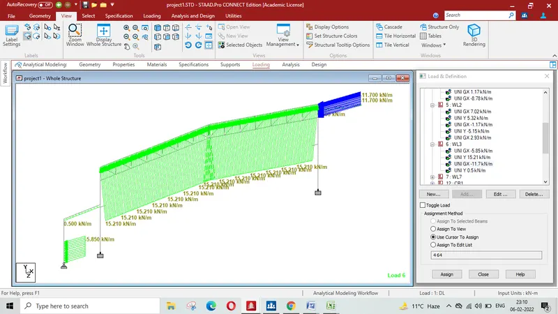
WIND LOAD CASE-3 : wind parallel the Ride ( 90 degree) with +v e `C_(p i)`
Roof angle `alpha = 5.71^0`
| Surface | `C_(pe)` | `C_(p i)` | `C_p=( C_(pe-C_(p i) ))` | wind load on frame`F = C_pxxAxxP_d` |
| A | -0.5 | 0.5 | -1.0 | -5.85 |
| EF | -0.8 | 0.5 | -1.3 | -15.21 |
| GH | -0.8 | 0.5 | -1.3 | -15.21 |
| B | -0.5 | 0.5 | -1.0 | -11.7 |
| C | -0.7 | 0.5 | -1.1 | -3.2175 |
| D | -0.1 | 0.5 | -1.1 | -22.5225 |
| Lean to | 0.41 | 0.5 | -0.09 | -0.5 |
| Extended roof | 0.41 | 0.5 | -0.09 | -0.5 |
Print screen of Load case-3
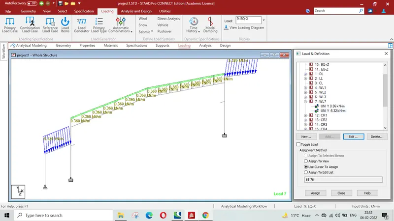
WIND LOAD CASE-4 : wind parallel the Ride ( 90 degree) with -v e `C_(p i)`
Roof angle `alpha = 5.71^0`
| Surface | `C_(pe)` | `C_(p i)` | `C_p=( C_(pe-C_(p i) ))` | wind load on frame`F = C_pxxAxxP_d` |
| A | -0.5 | -0.5 | 0.0 | 0.0 |
| EF | -0.8 | -0.5 | -0.3 | -0.36 |
| GH | -0.8 | -0.5 | -0.3 | -0.36 |
| B | -0.5 | -0.5 | 0.0 | 0.0 |
| C | -0.7 | -0.5 | -1.1 | -3.275 |
| D | -0.1 | -0.5 | -1.1 | -22.5225 |
| Lean to | 0.41 | -0.5 | 0.91 | 5.32 |
| Extended roof | 0.41 | -0.5 | 0.91 | 5.32 |
print screen of Load case-4
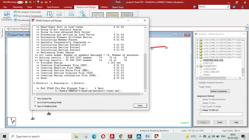
Print Screen showing Main frame in which Run Analysis command is performed successfully without any Error
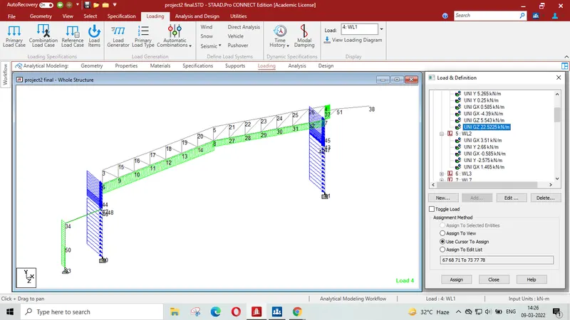
Gable frame is also analysed with load intensity 50% ( Dead load, live load and wind load only)of Main frame
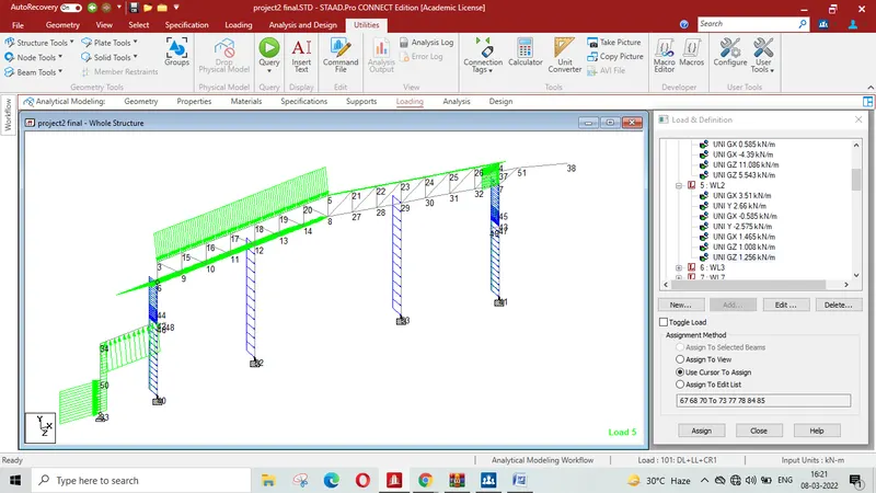
Print screen showing Wind load in Z direction due to gable frame
Print Screen showing Gable frame in which Run Analysis command is performed successfully without any Error
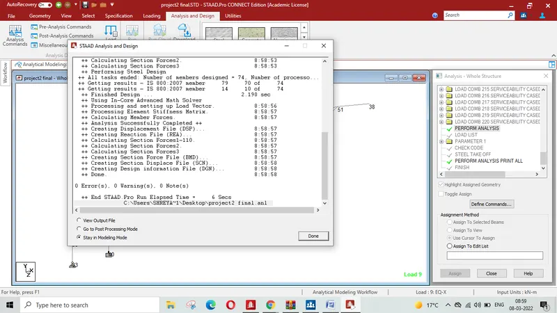
RESULT: Models is prepared with given inputs such as load, support condition, design parameters etc. and on postprocessing after Run Analysis, no error has been reported. Utilization Ratio is less than 1 for all the members. Slenderness Ratio, forces, moments are with in permissible limit. All the members are safe. Staad pro files for main and Gable frame is attached.