Project 1 - 2D meshing on the instrumental Panel
2D MESHING ON THE INSTRUMENTAL PANEL
AIM :
To check for the geometrical errors and mesh with the given element Quality criteria. After meshing the component the thickness has to be assigned.
PROCEDURE :
- Initially the given coponent is imported in the ANSA window as in the given format.
- Then the component is performed for topo such that the nearby cons get attched to one another and the this makes the process of attaching the surfaces easier.
- Next to topo the given component is checked for geometrical errors using the geometry check manager and the errors are listed down in the manager. Autofix of the errors is performed and still the errors which occur are fixed manually by suitable method.
- Now the component is free from geometrical errors and the perimeter and macro length are given in the perimeter option in the macros section.
- The component is made ready for midsurfacing and here the midsurfacing is done both manually and automidsurface. Automidsurface is performed for the surfaces except the doghouses and the ribs. As the other surfaces are of uniform thickness, skin offset in the automidsurface has created a perfect midsurface.
- The doghouses and ribs midsurface are created by either formig the middle curves of the geometry and the curve is projected on the below surface. Then on creating new surface with the created curves and cons will created the surface required.
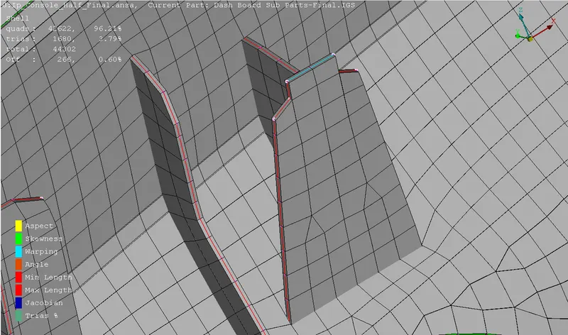
- The other way for creating midsurface of the above are using offset option in which the distance and directionfor offset is given and midsurface id formed. Middle surface option can also be used for creating midusrface of the above.
- After the midsurface is formed, it is checked for the attachment to skin offset surface. If the midsurfaces are not attached then the surfaces are extended towards the other surfaces such that a triple con is created at the region of attachment.
- Now the midsurface is formed and the quality critera and mesh parameters are given as input for meshing. Now the meshing has to be done for the surfaces.
- To make meshing easier and of proper mesh flow, the 2D meshing has to be started from complex regions and then towards the free edge/simple regions.
- Here the 2D mesh is performed using the best mesh option and remesh is done by reconstruct mesh option then the mesh is smoothened for better quality. Element nodes can also be moved for fixing quality issues using the move option in the macros.
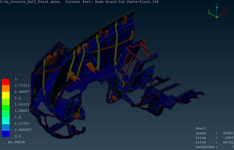
- Therefore the midsurface and mesh for the given component is performed and the thickness is also assigned to the 2D mesh by measuing the thickness of the parent component. For visual representation of the thickness, draw shell as solid option is switched on such that the thickness applied is visually conformed.
CAD MODEL IMAGES :
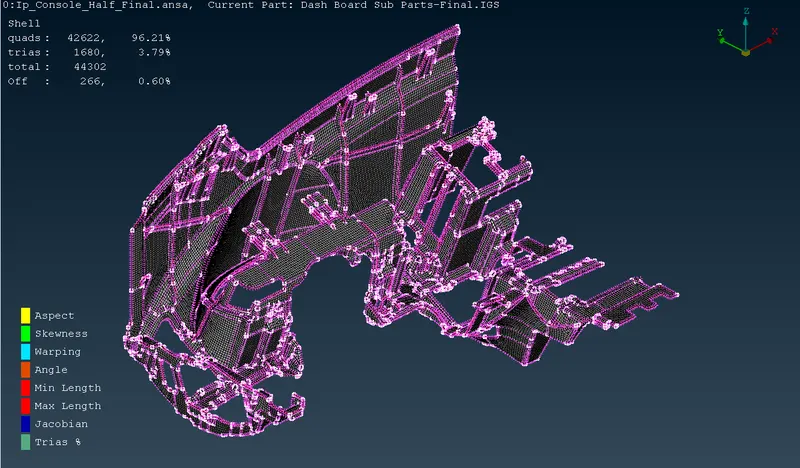
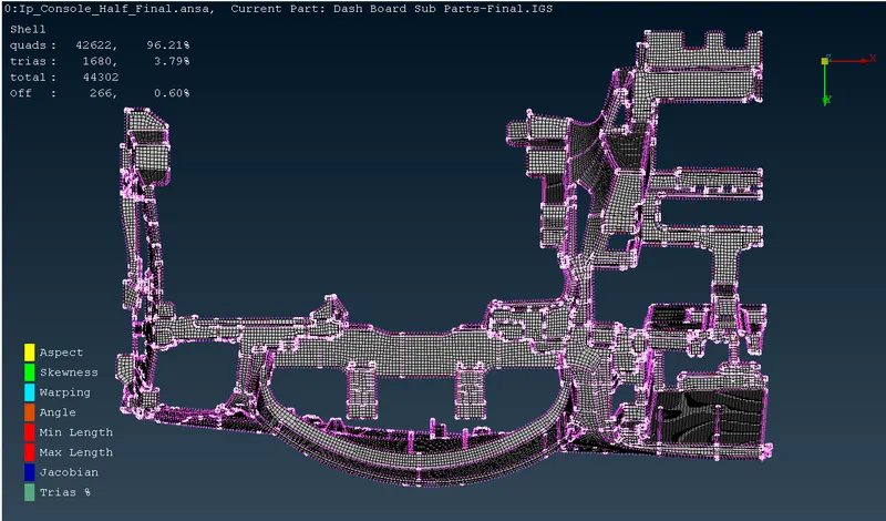
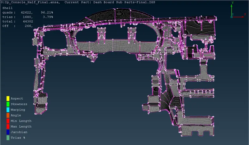
CONCLUSION :
Thus the geometrical errors and mesh with the given element Quality criteria is performed on the given component. After meshing the component the thickness is also assigned to the component successfully.