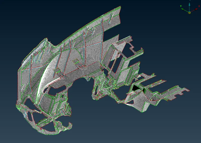
Project 1 - 2D meshing on the instrumental Panel
Question - For the given component, check for the geometrical errors and mesh with the given element Quality criteria. After meshing the component the thickness has to be assigned.
Objective - Write a detailed report on your meshing process and also mention which method you used to extract the mid-surface along with the reason.
IMPORTED MODEL:
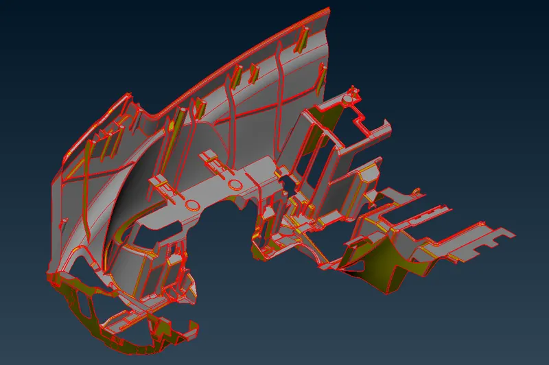
Step 1 - Geometry Cleanup:
- Gave topo to whole model.
- Correct the orientation in Entity Mode. By giving orient – Visible command.
- Open Property manager and rename each Property as per requirement.
- Select any one property & do show only command.
- Give show only to Selected part –
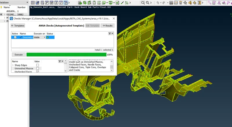
- Go to check manager. Check for Geometry.
- Triple cons error is showing in bulk.
- Give show only to Selected part –
- Select all triple cons error & give autofix command. Ansa will automatically fix the possible errors.
- Still some triple cons are showing.
- To remove select & show each triple cons. Use 1st neighbor command to show cons connected to this triple cons. Then release the cons connected to this triple cons.
- Now use delete hotspot command to delete extra hotpoints. Then add required hotspots & Give topo command.
- The triple cons will be removed.
GEOMETRY CHECK:
Step 2 – Midsurfacing:
Method 1 : Auto Midsurfacing commmand can be used with casting option. But as per complexity of the model this command distorts some features & areas of the model.
Method 2 : Manual Midsurfacing:
- Select and do show only on the part to be mid surfaced in Property manager.
- Now measure the thickness of part node to node of opposite faces using measure command. Now store the measured part through store command in measure dialog box.
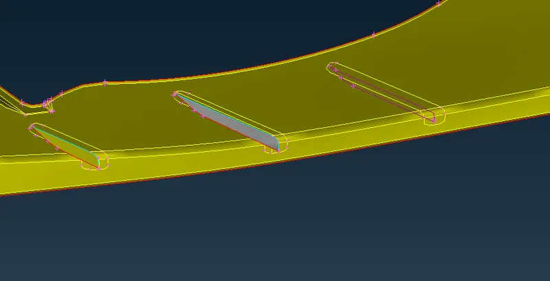
- Start manual midsurfacing with ribs first.
- Use offset command with value half of actual thickness. Try to offset all the ribs one by one.
RIBS MIDSURFACING:
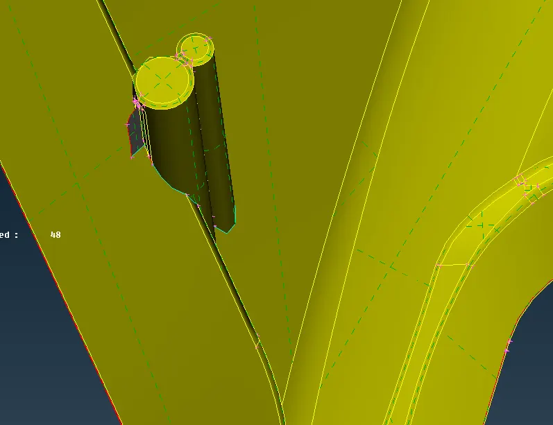
5. After Midsurfacing of ribs try to midsurface the dog houses in the model.
MIDSURFACING OF DOG HOUSES:
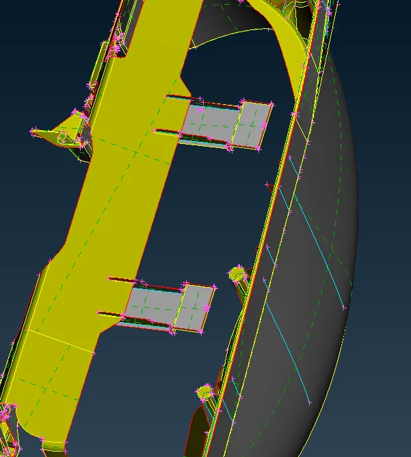
6. Afterwards take offset of remaining flat portions & hide the outer portion except the midsurfaced portion using I-Not command.
REMAINING PORTION MID SURFACING:
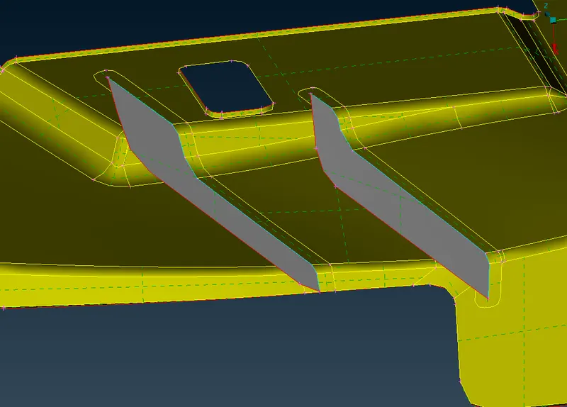
7. Now after getting all the midsurfaces. Use Extend command to Extend & Intersect the faces of ribs & body to each other.
8. Use Face>New>Coons to form faces which deleted or not availble during midsurfacing.
9. If ribs surfaces extrudes beyond the body surface give intersect command and select both intersecting faces. Then use delete command for extra extruded surfaces.
EXTENDING RIBS TO INTERSECT:
10. Assigning thickness to midsurfaced model. Select whole midsurfaced model and Use set PID command.
11. Go to Set Mesh Module>PID>New>PShell Then give value of thickness as per requirement>OK.
12. Now select the newly formed PID and select apply command.
Step 3 - Meshing :
- Now go to mesh module. Check the single element length using measure command & set the length required asper quality criteria using Length command.
- Check any inconsistency of length at the edges & curved parts. If found remove hot points to maintain the element length to required length.
- Set Quality criterias using F11 key to open quality criteria window.
- Set Criteria as per requirements. In presentation parameters > Graphics > Tick Element %. Also slide the point of Detail on demand effect to All details. Then Apply > OK
- Go to Mesh parameters tab and set target length as per requirement.
- Now start meshing parts which is more critical Feature first.
- To mesh use best command and select the areas to be meshed.
- After meshing open hidden view mode so that any quality criteria not fulfilled shall be visible.
- Correct the mesh pattern manually or using reconstruct command (Automatic) and fulfill the quality criteria. There shouldn’t be any trias at the perimeter of the geometry as well as no two trias opposite to each other.
- Some Off elements can't be resolved due to uneven triple coons formation due to intersection of parts. Leave it as it is.
- The macros should be bound to each other. There shouldn’t be any gap between mesh macros we have to paste the gaps. We can check this using bound option in drawing style tab. The bounding lines between two surfaces should be yellow.
- Always remember to keep the finite element & CAD to be bound.
- Now check for all quality criteria if showing no error then the model meshing is completed.
MESHING:
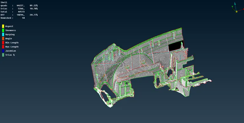
SPOT MESH AT UNMESHED AREAS:
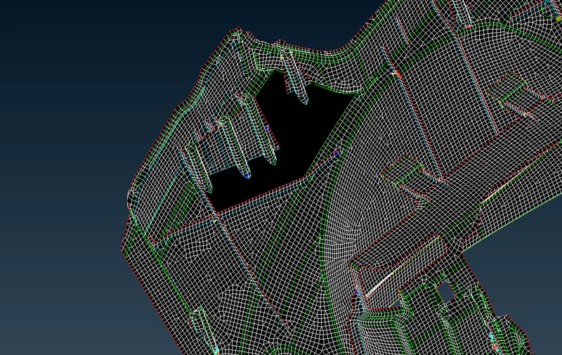
FINISHED MODEL :