Project 1 - 2D meshing on the instrumental Panel
Aim:
To perform geometry clean-up, mid-surface extraction, and mesh generation on the half part of the Instrument Panel of a four-wheeler vehicle adhering to the following quality criteria:
|
S.No |
Quality Criteria |
Value |
|
1 |
Target/Average length |
4 |
|
2 |
Minimum Length |
2 |
|
3 |
Maximum Length |
6 |
|
4 |
Aspect |
3 |
|
5 |
Warpage |
15 |
|
6 |
Skewness |
45 |
|
7 |
Jacobian |
0.7 |
|
8 |
Minimum Quad Angle |
45 |
|
9 |
Maximum Quad Angle |
135 |
|
10 |
Minimum Tria Angle |
30 |
|
11 |
Maximum Tria Angle |
120 |
|
10 |
Tria Percentage |
15 |
Procedure:
- Performing Topo / Geometry clean-up on the given model:
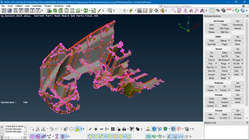
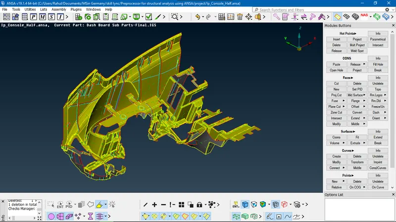
- The image shows the isometric view of half portion of Intrument Panel
- The resolution of the part is defined by the distance between the adjacent hot points on the perimeter and macros. The resolution is low by default. To get a refined view of the part, resolution is increased using MESH > Perimeters > Lenght function. In selection window, Perimeters and Macros are selected one by one and in the length field the value is set to 1 mm.
- When the adjacent faces are not connected to each other, edges of the face are represented by single cons (red lines). The surfaces are connected using TOPO > Faces > Topo function and selecting the whole part. On confirmation, doubles cons (yellow lines) are formed and faces get attached.
- Geometry is checked using Menu bar > Tools > Checks > Geometry. In the template, all the geometric failures are ticked and the check is executed. The check manager shows all the encountered errors:
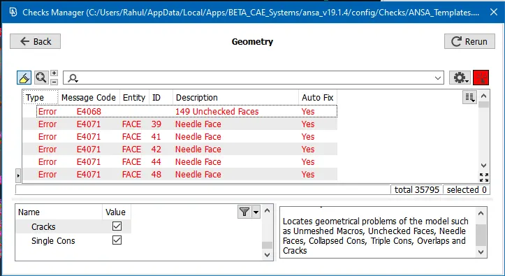
- All the errors are selected and fixed automatically using right-click > Fix function
- The checks manager is rerun and unchecked faces and collapsed cons appear as errors. Since these errors were not fixed automatically, they are fixed manually. The errors are found by using right-click > Show only. The neighbouring entities are made visible using Menu bar > Focus > Neighb
- All the unchecked faces are deleted and recontructed using TOPO > Faces > New function.
- After manually clearing out the geometrical issues, the following result is obtained:
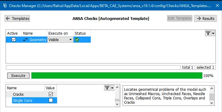
- The status signifies that the geometry is good to go.
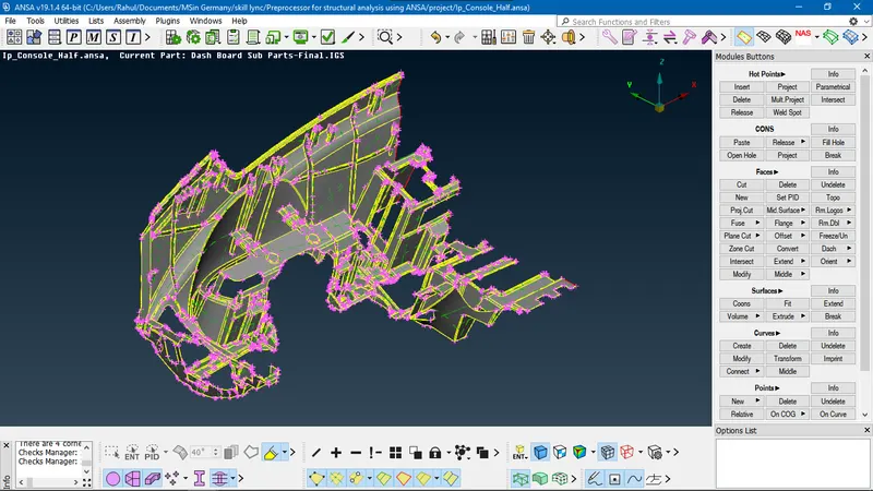
- This shows the clean geometry
- Extracting Mid-surface:
- Mid-surface is the representation of the whole CAD model without the thickness. It captures the whole component with all the features on it in a single layer surface.
- The mid-surface can be automatically generated in a go using Skin and Casting option available in TOPO > Faces > Mid. Surface
- Skin method is used for the whole component and following result appears:
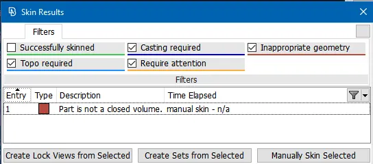
- It shows that ANSA could not skin and it suggests Casting method. It says that geometry is inappropriate since the part is not closed volume. As the part is cut in half, it is not a closed volume, hence it cannot be skinned.
- The casting method suits best for plastic parts (having variable thickness). Since the part has complicated geometry (having ribs, fillets and dog houses) Casting function is not preferred. Casting method fails to capture the complicated geometry and generates a lot of failed elements.
- Hence the manual method is prefferred. Manual mid-surfacing is done using TOPO > Faces > Offset. The bottom side of Substrate of the Instrument Panel is selected using feature angle selection tool.
- Offset function replicates the selected faces by regenerating the same at an offset distance. In the Offset window, offset value is set to -0.3 mm. Since the thickness of the substrate is 0.6 mm, mid-surface is generated in the middle of both sides of geometry.
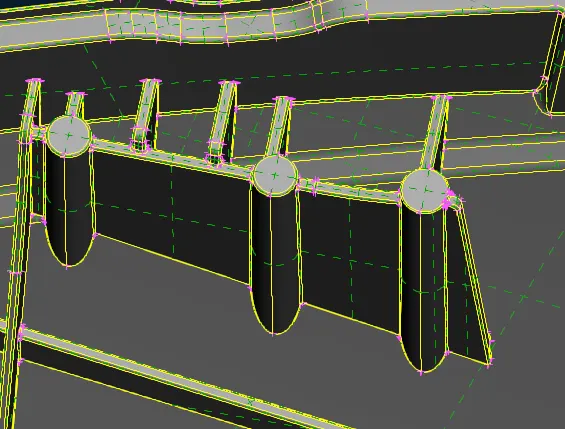
- This shows the dog houses and ribs on the top portion of substrate.
- The midsurface of the ribs is captured using TOPO > Faces > Middle function. Both sides of the faces are selected (neglecting the thickness) and a new face is generated in between both the selected faces.
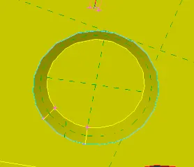
- The dog house are hollow cylindrical structures. So the mid-surface is captured by cross faces. Cross faces are created by creating curves using TOPO > Curves > Create. The curves are used to create new faces of the width same as diameter of the dog houses.
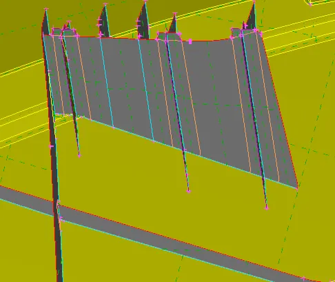
- These surfaces are connected to the substrate mid-surface using TOPO > Faces > Extend function. The single cons are selected that are supposed to be extended and a face is selected to which the entity needs to be connected. On connection, single cons convert to triple cons (cyan lines) as shown below:
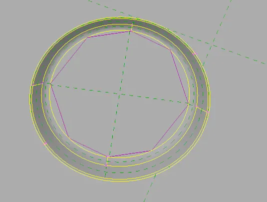
- This feature is extracted by converting the inner circle into a curve using TOPO > Curve > Cons2Curves.
- The outer circle is projected to the substrate mid-surface using TOPO > Cons > Project function. The circular con is selected first and then the face is selected for projecting
- Both: the projected con and curve is used to create a new face using Faces > New > Coons function as shown below:
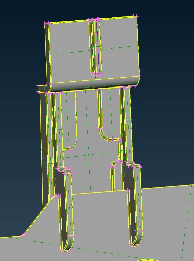
- The extending are recreated using Faces > Offset function and feeding the offset value as half the thickness.
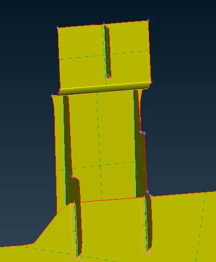
- The side ribs are recreated using Faces > Middle function
- The ribs are extending to connect with both mid surfaces as shown below:
- The image shows the mid-surface of the whole part
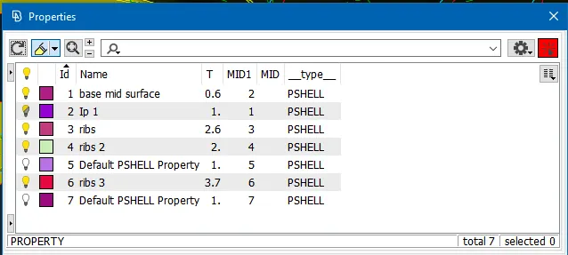
- Thickness is assigned to each face using Faces > Set PID. New Part ID is created by right-click > New > PSHELL in Menu bar > Lists > Property. The thickness of the parent geometry is measured and using Utilities > Measure function and fed into the property card.
- Setting the quality criteria:
- Quality setting is done in Menu bar > Utilities > Quality criteria:
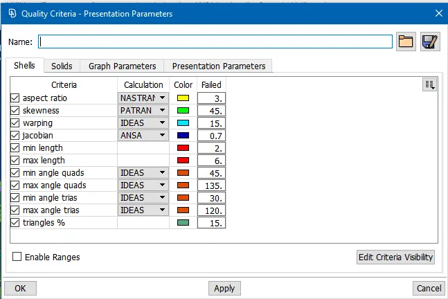
- These parameters are the minimum and maximum requirement for the size of finite elements.
- Aspect ratio demands that the ratio of maximum length to minimum length of an element should be less than or equal to 3
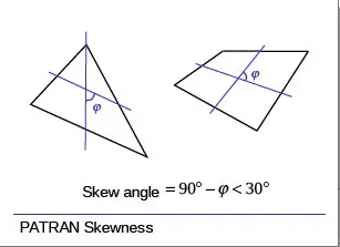
- Skewness demands that skew angle to be less than 45 degrees
-
- Warping is for the quad elements that bend into two planes. Warping angle is the angle made by the normals of two planes of quad and it should be less than 15 degrees.
- Jacobian defines the shape of finite elements. Ideally shaped element has jacobian of 1. The minimum requirement is 0.7.
- The side length of any element can only be in the range of 2 to 6 mm.
- Quad angles are the angles made by the intersecting median lines
- Tria angles are the angles made by median line and a line between a vertex and opposite median.
- The trias can only be 15 % of the total finite elements
- The mesh parameters are also set in Menu bar > Utilities:
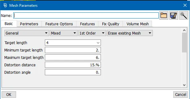
- The ideal length of element is set to 4 mm
- Type of mesh elements is set to mixed: consisting of quads and trias.
- Quality setting is done in Menu bar > Utilities > Quality criteria:
- Generating mesh:
- Geometry checks is performed on the mid-surface and issues are cleared out
- Since the required mesh element size is 4 mm, the perimeter and macro nodal length is changed from 1 mm to 4 mm using MESH > Perimeters > Length function
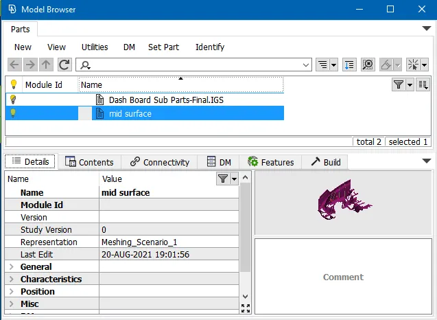
- New Part is set for the mid-surface using Menu bar > Model browser > Set Part and selecting the whole mid-surface only
- Mesh is automatically generated for the whole mid-surface using Menu bar > Tools > Batch Mesh
- Batch mesh method is preferred since the component is large with higher surface area

- In the Batch Mesh Manager window, Meshing Scenario is created in New
- The content for mesh is set in Contents. In Contents window, mid-surface model is selected and added to mesh scenario using the green arrow
- The manager window also asks for Quality criteria and Mesh parameters that are previously set.
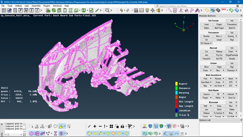
- The Batch Mesh gives the above shown result.
- The Off elements are the elements that are failing for the quality criteria
- These elements are manually tried to be fixed using functions like MESH > Shell Mesh > Reconstruct and Smooth
- The trias formed on the free edges and feature lines are removed using MESH > Elements > Split function.
- The opposite trias, the rotating quads and the adjacent trias are eliminated using Split function and/or Paste function in MESH > Grids
- The quality failures that cannot be cleared using above mentioned functions, are tried using Grids > Move function. this function displaces the grid on the same surface in any direction as cursor movement.
Conclusion:
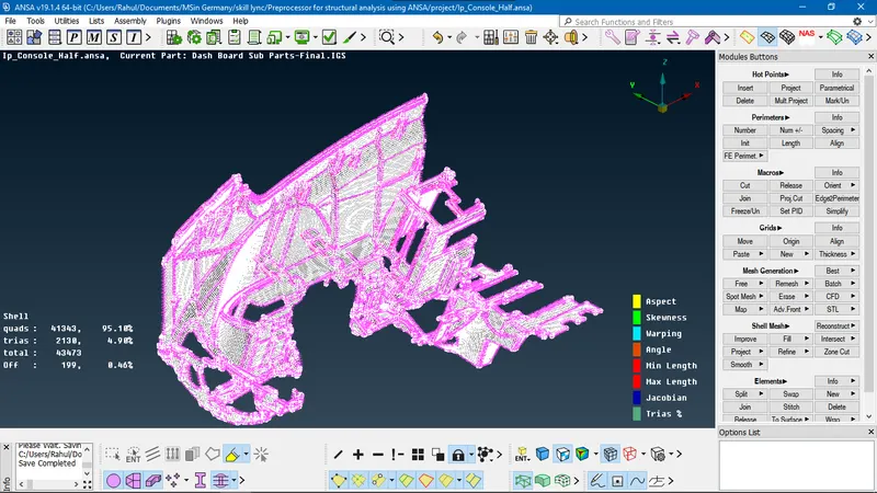
The quality failures are reduced from 442 to 199. The off elements could not be removed completely due to the close-lying triple cons and single cons. The triangle percentage is 4.9 % which is well below the permissible limit. The thickness is enabled for mid-surface FE by enabling Draw Shell as Solid in Quality Criteria > Presentation Parameters.
Learning outcomes:
- Batch Mesh is a great tool for meshing large and complicated geometry. It automatically defeatures by suppressing the cons in the tight regions where element failures occur.
- When a new face is created using COONs, the adjacent faces do not merge into a single face after suppressing the connecting double con. Whereas when new face is created using Existing Surf method, on suppressing the double con, faces merge.
- Unchecked faces are usually invisible. Its presence can be determined by turning on the Cross Hatches in Menu bar > Faces Draw. Unchecked faces are eliminated by deleting them and recreating new faces.
DRIVE LINK:
https://drive.google.com/file/d/1tXyH7ogTY4qzyj3oGllEa48Bw09WT3Gn/view?usp=sharing