Project 1 - 2D meshing on the instrumental Panel
Project-1 2D Meshing of Instrumental Panel Console
AIM:
To generate a 2D mesh for the given Instrumental Panel Console model by taking Mid Surface for each component present in the model after clearing the geometrical errors present in the model followed by meshing with the given Quality Criteria.
PROCEDURE:
The following diagram provides the flow chart of the work being progressed for meshing the given IP Console model.
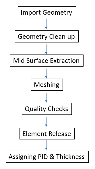
Fig.1 Flow Chart
Geometry Import: First the Instrumental Panel Console model has been imported to the Ansa software and preliminary checks on the geometry have been carried out. The preliminary checks include the geometry error checks. If any errors present in the model were cleared later. Figure 2 provides the topological/geometrical model imported into ANSA.
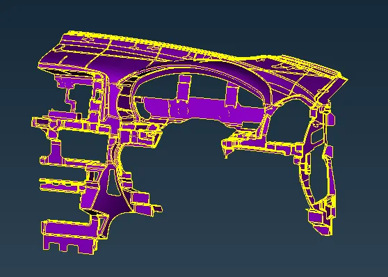
Fig. 2 The IP Console imported into ANSA Software
Geometry Clean-up: The geometrical errors present in the model have been cleared and the below figure provides a visual aid for the cleared geometry.
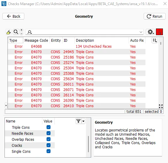
Fig. 3 Geometrical Error Check made on the model.
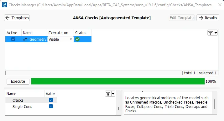
Fig. 4 Geometry Errors cleared.
The model has been checked and cleared for geometrical errors. Figure 4 shows that the given model is free from geometrical errors. After that orientation of the model has also been carried out.
Mid Surface Extraction: After the model has been cleared for the geometrical errors, the Mid Surface of each component has been extracted by splitting into many parts for easy extraction and meshing followed by assigning a separate PID for each. For easy Mid Surface Extraction, the model has been separated into many parts as shown in figure 5. Figure 6 shows the mid surface of the entire model and figure 7 provides details of the PID assigned respectively.
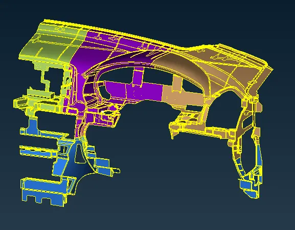
Fig. 5 Split Up Portion of the Given Model.
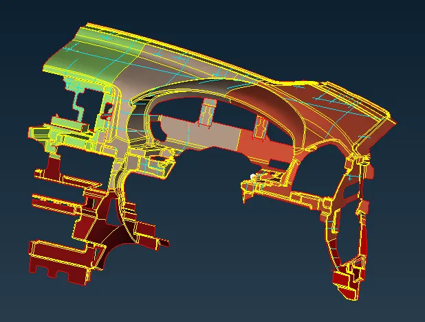
Fig. 6 Mid Surface Extracted for each Component.
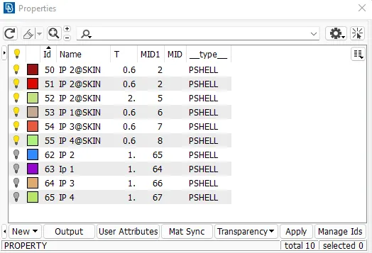
Fig. 7 Separate PIDs assigned for each component with respective thickness.
Meshing: After mid-surface extraction, meshing has been carried out on the mid-surface with the following mesh parameters shown in figure 8.
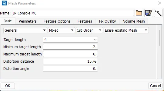
Fig. 8 Mesh Parameters.
Figure 9 shows the mesh created on the mid-surface extracted.
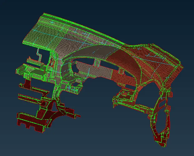
Fig. 9 Mid Surface Meshed.
Quality Checks: After mid-surface meshed, quality checks have to be performed and the mesh should be free from quality errors. Figure 10 shows the Quality Criteria set for the given model.
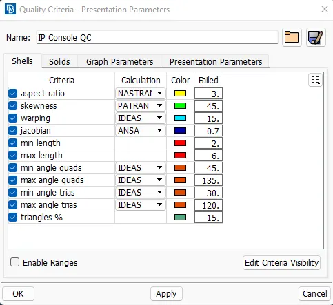
Fig.10 Quality Criteria Check.
The quality check was performed and quality errors were cleared. The mesh model free from quality error is shown the figure 11.
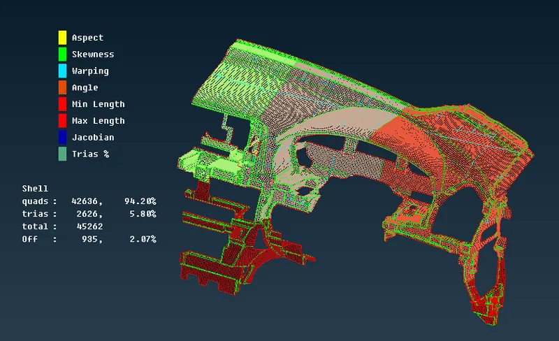
Fig. 11 Quality Checks performed on the mesh.
Element Release: After the quality checks, the mesh elements were released from the mid surface and assigned to a separate PID. Figures 12 and 13 show only the model's mesh model and PID data.
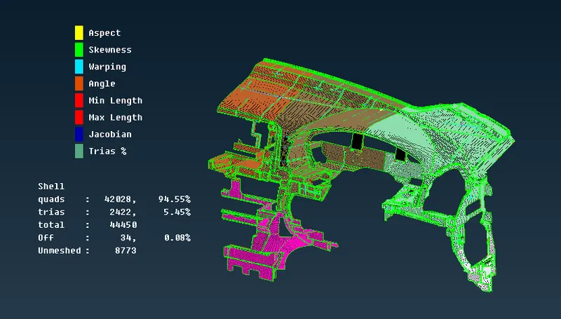
Fig. 12 Mesh-only Model.
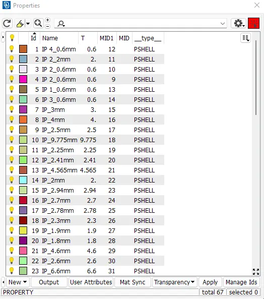
Fig. 13 Mesh PID Details.
Assigning Thickness: The model has been provided with properties namely Thickness, Material, Name, and Ids. Finally, the elements were drawn as solids. Figure 13 shows that thickness has been assigned to each component and figure 14 & 15 shows the mesh elements of the entire model drawn as solids to reflect the actual CAD geometry.
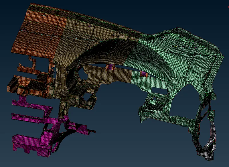
Fig. 14 Elements drawn as solids.
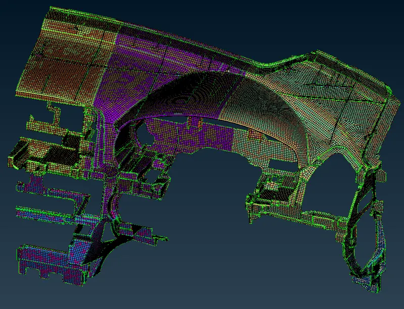
Fig. 15 Elements drawn as solids of meshed model and original CAD model.
LEARNING OUTCOMES:
- Mid Surface Extraction for any complicated geometry.
- Easy meshing with different mesh options.
- Meshing of complex structure/components by splitting into many parts/cut portions.
- Good mesh flows throughout the model.
- Assigning appropriate thickness for each component.
CONCLUSION:
The Shell Mesh with thickness is only the thing that represents the CAD Geometry model in the software, as software only can understand the shell nodes with their node id and location, So, a good mesh will always reflect the Cad model originally in software language, therefore, reduces the time during simulation or analysis. Hence proper pre-processing will aid in getting better results and also as it reflects the original CAD, it helps to understand the model properly to ensure better use of the model.