Project 1 - 2D meshing on the instrumental Panel
Project 1: 2D MESHING ON THE CARS INSTRUMENTAL PANEL
Objective: The Main Objective of this Project 1 is to Mesh the Instrumental Panel as per the given Quality Criteria and Assign the Thickness.
Quality Criteria: Quality Criteria shown in table no. 1
Table 1. Quality Criteria Table
|
Sr. No. |
Quality Criteria |
Value |
|
1. |
Target/Average Length |
4 |
|
2. |
Minimum Length |
2 |
|
3. |
Maximum Length |
6 |
|
4. |
Aspect |
3 |
|
5. |
Warpage |
15 |
|
6. |
Skewness |
45 |
|
7. |
Jacobian |
0.7 |
|
8. |
Minimum Quad Angle |
45 |
|
9. |
Maximum Quad Angle |
135 |
|
10. |
Minimum Tria Angle |
30 |
|
11. |
Maximum Tria Angle |
120 |
|
12. |
Tria Percentage |
15 |
Procedure:
- Import Cad Geometry = File - Open - Select Geometry.
- The given CAD Geometry imported in ANSA workbench and orientation checked.
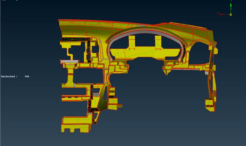
- Image 1: Imported CAD Model (Instrument Panel)
- Geometry Clean-UP = Tools - Checks - Geometry. Errors are resolved automatically by using fix command in geometry.
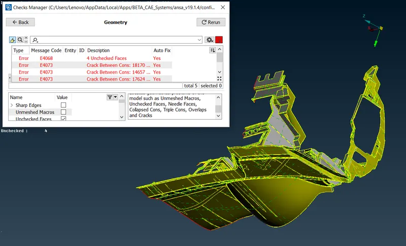
- Image 2: Before Geometry Clean-up
- Topo - Faces - Topo Command used to clear issues with the orientation
- All geometrical errors are cleared using auto FIX option.
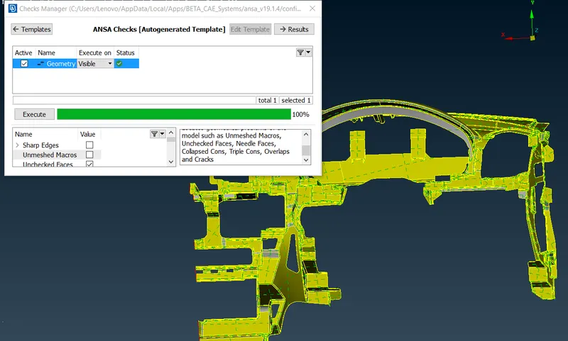
- Image 3: After Geometry Clean-up
- Thickness Measurement : Thickness measured using Utilities - Measure. As this is a Plastic Component (Instrumental Panel) It has a same thickness throughout the model as shown in Image 4.
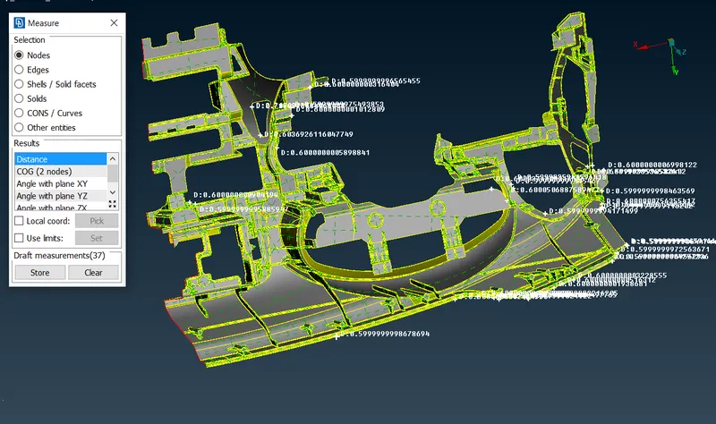
- Image 4: Thickness Measurements
- PID Creation: Separate Property ID Created for all different part IDs.
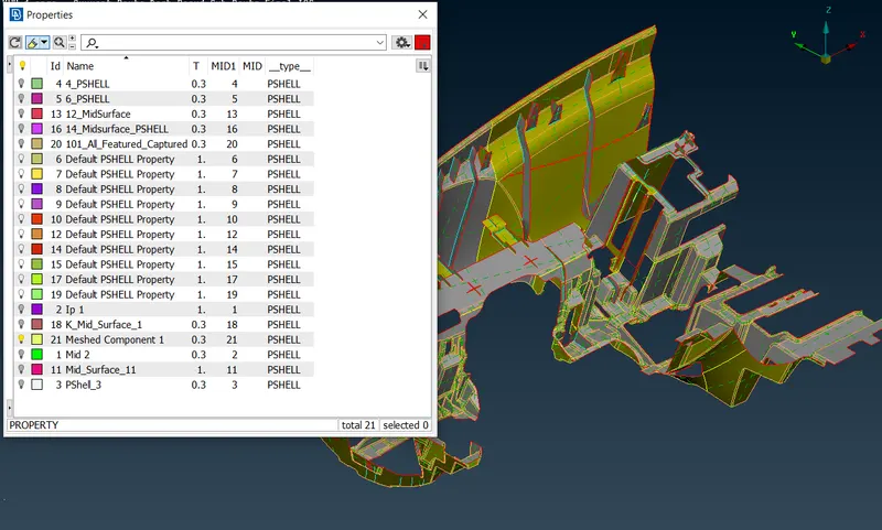
- Image 5: PID Creation
- Mid Surface Generation:
- The resolution of CONS improved using Mesh - Length - Perimeters - Macros.
- Topo - Faces - Offset, Topo - Faces - Middle used to find the mid surface.
- Also, Topo - Faces - New / Cut, Topo - Cons - Project, Transform - Copy - Rotate Commands used to find the mid surface.
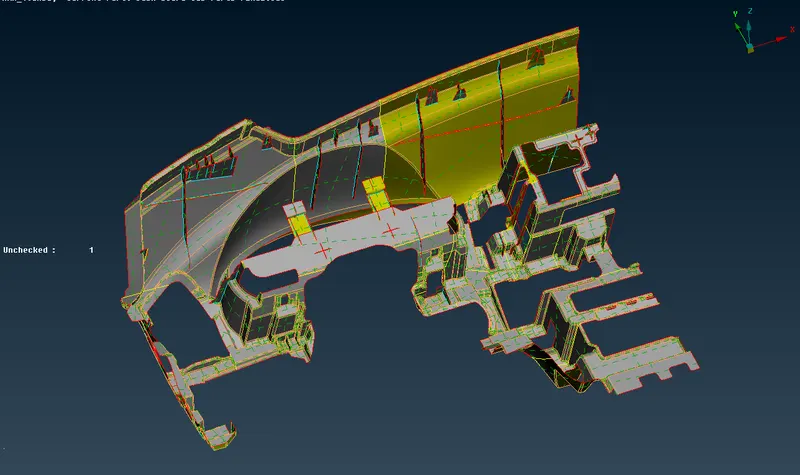
- Image 6: Mid Surface
- Mesh Generation : The perimeter elemental length is set using Mesh - Perimeter - Length, Mesh - Perimeter - Macro option.
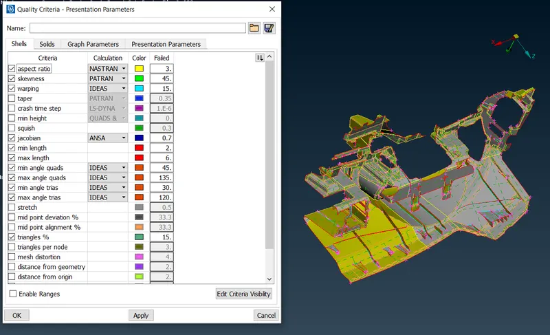
- Image 7: Quality Criteria - Presentation Parameters
- The Quality Criteria Shown in table no. 1 are applied to the model using utilities - Quality Criteria
- Mesh Parameters are applied using Utilities - Mesh Parameters.
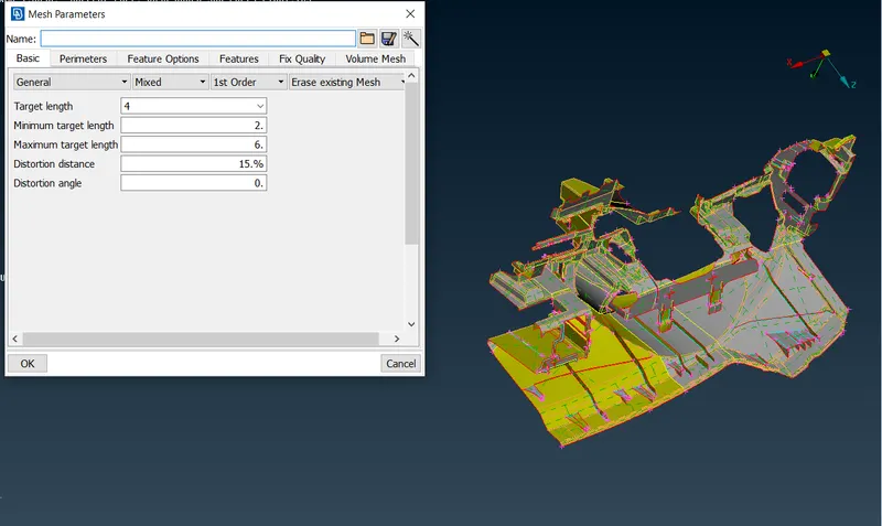
- Image 8: Mesh Parameters
- F11 Function Key is a shortcut for Quality Criteria - Presentation Parameters.
- Mesh is done using Mesh - Mesh Generation - Spot Mesh.
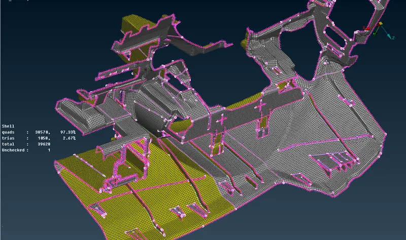
- Image 9: Mesh Generated
- For better results of mesh Mesh - Shell Mesh - Reconstruction used.
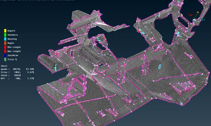
- Image 10: Mesh Generated as per Quality Criteria
- Mesh Improvement is done using Reconstruct, Smooth, Split, Swap, Paste, Cut, Join etc under Mesh tab.
- The surfaces are split to get better mesh flow using Mesh -Macros -Cut.
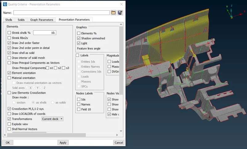
- Image 11: Draw Shell as a Solid Command
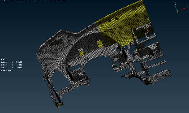
- Image 12: Thickness Assign to the Meshed Component
- Result : The given Instrumental Panel is meshed as per the given quality criteria. The thickness assigned to the meshed Instrument Panel.
- Conclusion : From this challenge I learned about Instrument Panel CAD model import, Geometry clean-up, New PID creation, Mid surface extraction, setting up Quality Criteria, Mesh generation, Reconstruction of mesh using quality criteria, Assigning Thickness to Meshed Model.