Project 1 - 2D meshing on the instrumental Panel
Aim: For the given component checking the geometrical errors and mesh the model with given quality criteria. After meshing thickness as to be assigned.
|
S.No |
Quality Criteria |
Value |
|
1 |
Target/Average length |
4 |
|
2 |
Minimum Length |
2 |
|
3 |
Maximum Length |
6 |
|
4 |
Aspect |
3 |
|
5 |
Warpage |
15 |
|
6 |
Skewness |
45 |
|
7 |
Jacobian |
0.7 |
|
8 |
Minimum Quad Angle |
45 |
|
9 |
Maximum Quad Angle |
135 |
|
10 |
Minimum Tria Angle |
30 |
|
11 |
Maximum Tria Angle |
120 |
|
10 |
Tria Percentage |
15 |
Procedure:
- Importing the given file. As the given model is an instrument panel i.e, plastic component it can be meshed using the 2D shell elements, before meshing the geometry clean up is to be done and then mid surface extraction is done.
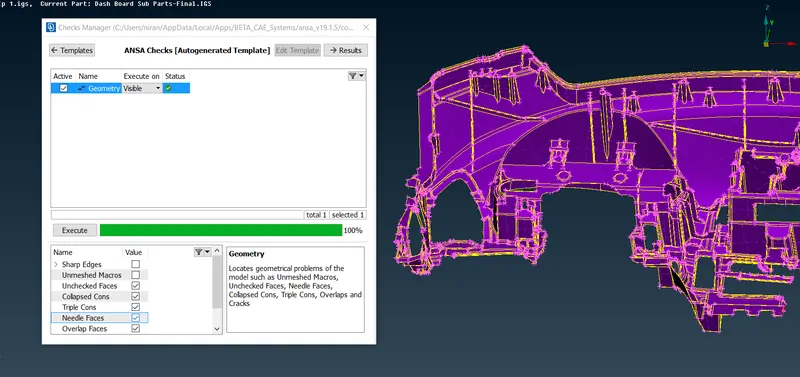
- First, the geometry checks have been done using tools > checks > Geometry, and clicking on the geometrical problems of the model such as Unchecked Faces, Needle Faces, Collapsed Cons, Triple Cons, Overlaps, Single cons and Cracks. Clicking on the execute option and finding the errors in the surfaces. If any errors are found that has been cleared using the automatic fix option or manually cleared using the topo options.
3. After clearing the geometrical errors thickness measurement has been taken randomly as it is different thickness all over the component so the mid surface is extracted using Topo > faces > offset > faces. Selecting the faces on any one side and giving the offset value of exact middle and creating the mid surface or by creating the curves on the middle surfaces and creating the new surfaces using that curves and extending to the surface.
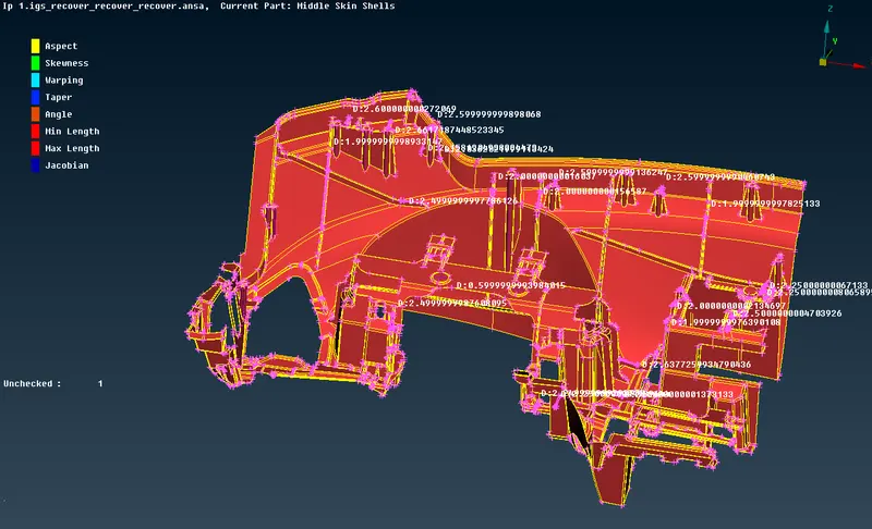
4. After creating the mid surface selecting the whole mid surface and store the mid surface using the Lock > store lock option.
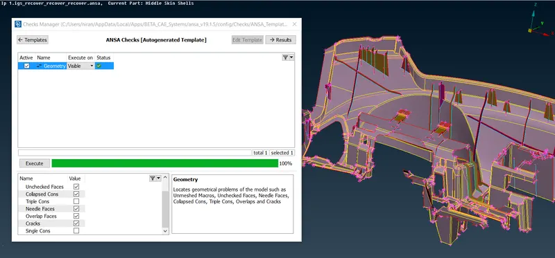
5. Again the geometrical errors as been checked for mid surface using the tools > checks > Geometry, and clicking on the geometrical problems of the model such as Unchecked Faces, Needle Faces, Collapsed Cons, Triple Cons, Overlaps and Cracks. Clicking on the execute option and finding the errors in the surfaces. If any errors are found that has been cleared using the automatic fix option or manually cleared using the topo options.
- After clearing the mid surface errors the given quality criteria values as been assigned using the quality criteria option selecting whichever criteria needed and adding the values to it and in mesh parameters giving target length, min length and max length values.
- Using mesh options mesh generation > best > select, options mesh as been created on the surfaces one by one and for proper mesh using mesh > mesh generation > reconstruct > select, options are used for good mesh and get the mesh to flow good smooth option is used.
- While meshing, these are the things I followed, there should be zero elements failure according to the given quality criteria, feature capturing, mesh flow.
- Other than the above criteria the main thing is the management of trias like no tria should be on the corner or edges of geometry, no opposite trias, no back to back trias, no rotational quads, no tria should share with any of the features etc.,
- After completing the mesh for assigning the thickness mesh > macros > set PID > selecting the faces > by clicking on the right click > new > Pshell > giving the thickness value > then press Ok
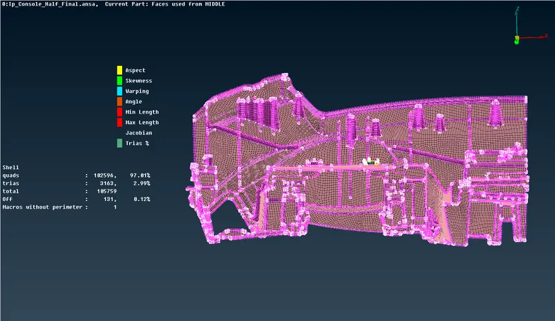
- Final Model with 2.99% Tria element and 0.12% off elements near triple cons.
Learning outcomes :
- Learnt the geometrical errors fixation for complex components.
- Learnt to extract the mid surface for complex components.
- Learnt to do the meshing in complex areas by creating the new lines for a closed set of lines where minimum element length going to fail.
Conclusion :
As per the given objective geometry clean up has been done and as per the given quality criteria the given model meshes accordingly and thickness is assigned for each part. Tools used are property, checks, mesh parameters, quality criteria, transform, measure. For selecting any surface or faces ENT, PID, Macro Area, feature options are used according to the requirement. For masking and unmasking the surfaces or, and, not, inot, all, invert, lock, neighbour options are used. In topo model insert, delete, weld spot, release, cut, delete, set PID, topo, Project cut, Rm Dbl, offset, orient, fine etc., In mesh module insert, delete, number, num+/-, length, slide, cut, edge2peri, move, best, remesh, batch, erase, map, smooth, reconstruct, split etc.