Project 1 - 2D meshing on the instrumental Panel
Aim
>> To extract the midsurface for the given plastic component and to mesh it according the below quality criteria.
|
S.No |
Quality Criteria |
Value |
|
1 |
Target/Average length |
4 |
|
2 |
Minimum Length |
2 |
|
3 |
Maximum Length |
6 |
|
4 |
Aspect |
3 |
|
5 |
Warpage |
15 |
|
6 |
Skewness |
45 |
|
7 |
Jacobian |
0.7 |
|
8 |
Minimum Quad Angle |
45 |
|
9 |
Maximum Quad Angle |
135 |
|
10 |
Minimum Tria Angle |
30 |
|
11 |
Maximum Tria Angle |
120 |
|
10 |
Tria Percentage |
15 |
Procedure
>> The given plastic component is imported into ANSA using File>Open function.
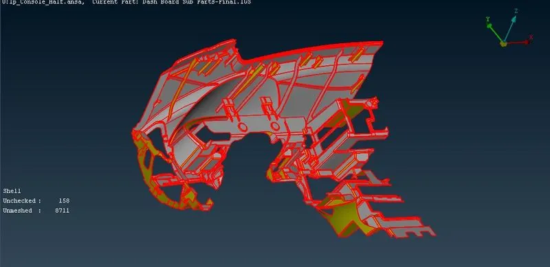
>>Topo function is performed on the model. The adjacent faces are joined to each other by this function as shown below.
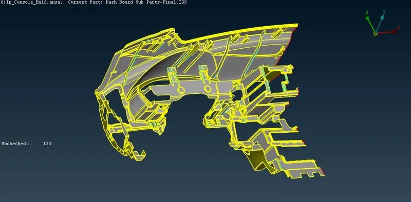
>> The face are oriented to the right direction via the Faces>Orient function in the Topo module.
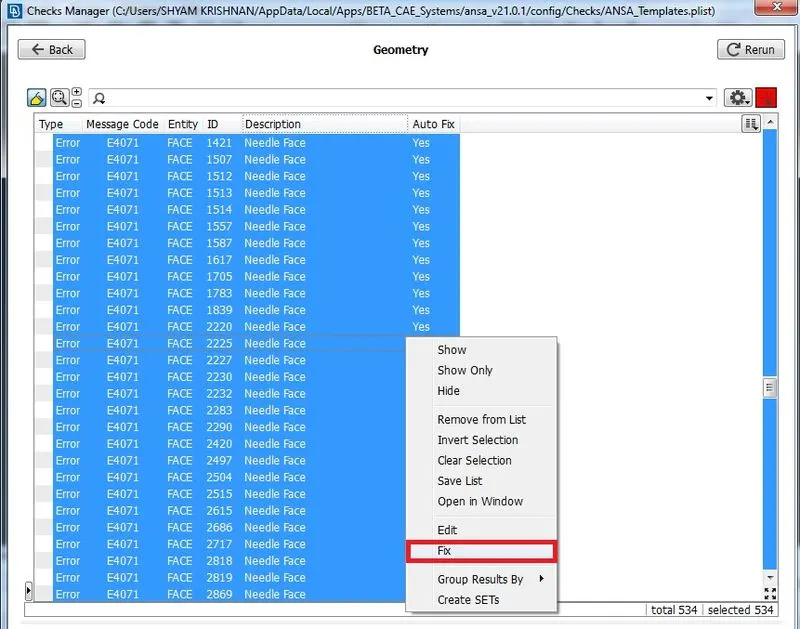
>> The various geometry checks are done using the checks manager in ANSA. Various problems such as needle face, cracks are found by the checks manager. Fix option is used to clear most of the problems.
>> The remaining areas where ANSA cannot fix automatically is checked and are repaired by deleting damaged face and creating new faces, releasing CONS and deleting unnecessary hot points and perfoming TOPO function on the released CONS.
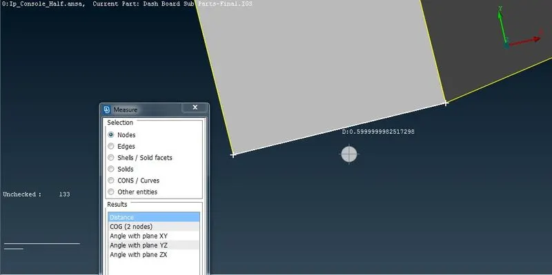
>> As this is a plastic component, the thickness is not uniform. so the thickness is measured at various places using the measure tool in Utilities>Measure and then selecting Nodes/Edges as shown below.
>>After measuring the thickness, the midsurface is extracted by using the middle and offset functions under the Faces section of the Topo module.
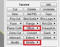
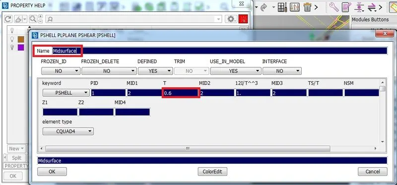
>>This process is repeated again and again until each part of the parent geometry is converted into a shell surface. For each surface with varying thickness a different PID is assigned and the measured thickness obtained from parent geometry is provided as the thickness input.
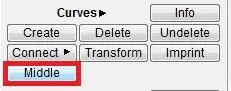
>> To take midsurface of surfaces with varying thickness, a middle curve is generated by executing the function 'Middle' under the curves group within the Topo Module. The generated middle curve is then converted into midsurface by creating new faces with the created curves as one of the face edges.
>> The different thickeness regions are sorted under different PID's and thickness is assigned accordingly.
>> To interconnect the ribs with the main body, the Faces>extend and the Faces>intersect function is used. Triple CONS are formed under such junctions.
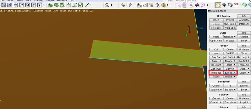
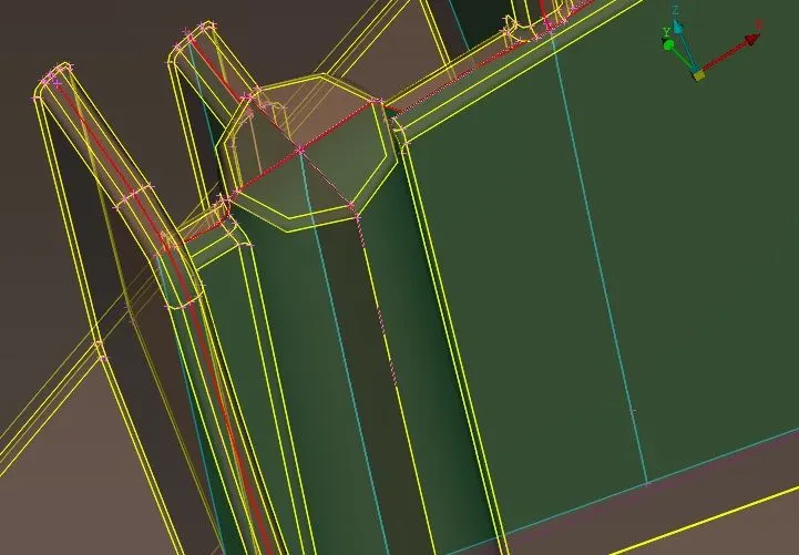
>>The midsurface of dog houses are created by making two surfaces crossing each other as shown below.
>> After inteconnecting the mid surface, the mid surface is checked for geometric problems using the checks manager.
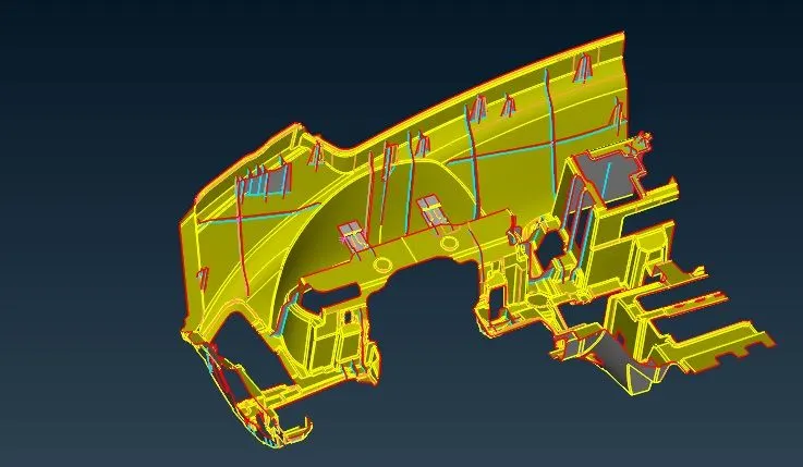
>> Geometry cleanup is done on the completely extracted midsurface by toggling the CONS in areas lesser than the minimum element length and also by re arranging the CONS. The midsurface after Geometry cleanup is shown below.
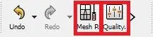
>> The meshing parameters and the quality criterira are entered as required in the question as shown below. Both these parameters are accessed from Menubar>Utilities
.
>> In meshing back to back trias, trias near edges, fillets, circular openings and tria concentration are avoided using various tools such as 'Swap', 'Split' and 'Join' functions under 'Elements' in Mesh module. Also the paste function under the 'Grids' is also used to combine adjacent nodes to move the trias away from each other.
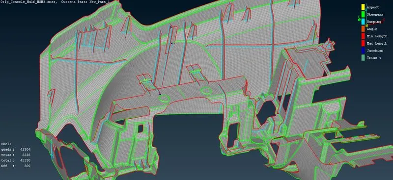
>> The final mesh obtained is shown below.There are some failed elements near to Triple CONS or at smaller regions which are bounded by two Triple CONS. Those OFF elements are kept as it is if not possible to solve them.
>> The FE elements are released from midsurface geometry using the Faces>Elements>Release function and thickness was given to elements in areas where different types of features are present on both side of the IP Console and those elements were sorted in seperate PID's. The 'draw shell as solid' option in the presentation parameters is enabled to visualize the thickness assigned of the elements.
Learning Outcomes
>>Acquired knowledge of taking midsurface for plastic component with different features on both sides of the surface.
>>Various problems occuring during extraction of midsurface of plastic component with various interconnections and jucntions was identified and its trouble shooting skill was acquired.
>>It was understood that small percentage of elements failing for quality is inevitable during meshing of plastic component with complex shapes along with triple cone boundaries.
Conclusion
>>The 2D meshing process of the IP console was completed using the required meshing parameters and quality criteria given in the question and an acceptable mesh was obtained.