Project 1 - 2D meshing on the instrumental Panel
Objective:-
2D meshing on the instrumental Panel
Solution Procedure:-
Solution Procedure:-
Step 1:-
- Read the CAD file Perform the topology using the topo option.
Step 2:-
- Perform the geometry cleanup and check the geometry.
Step 3:-
- Measurement and assessment of the thickness of different components were done.
Step 4:-
- Performing the Mesh generation by using different commands was done.
Step 5:-
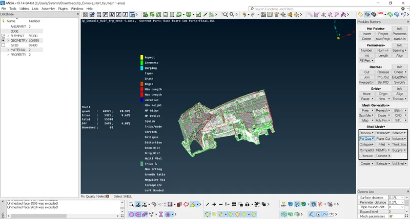
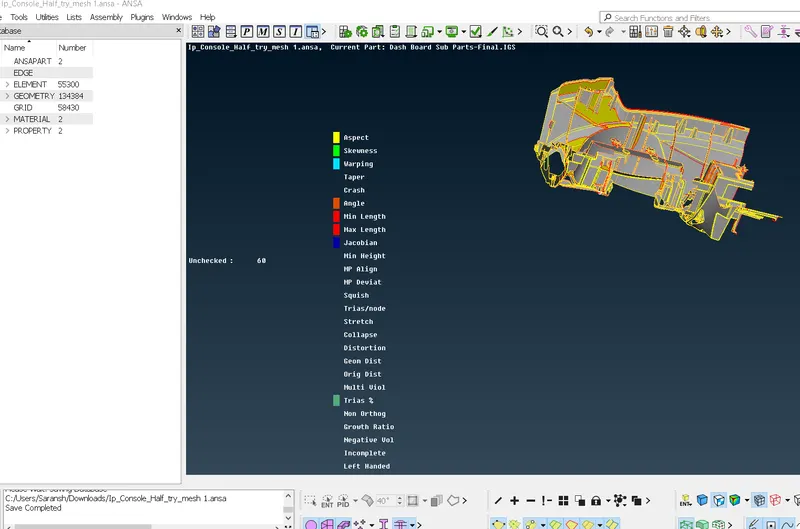
- A quality check was performed within assigned parameters and resolved using different tools.
____________________________________________________________________________________________
Topology and Geometry Cleanup:-
Importing CAD - The CAD geometry designed by a CAD/Design engineer can be imported into the ANSA software either as a .step or as a .iges format. These are the most popular CAD formats that ANSA recognizes.
It is recommended to set a specific limit on tolerance and resolution prior to importing the CAD.
There is a high chance that the imported CAD may face having some errors. These errors may include orientation issues, duplicate or missing surfaces, sharp edges (which could cause errors while meshing), etc. Initially, every model has to be checked for geometrical errors. Prior to this, it is best practice to perform a topology clear-up to make sure that continuity is maintained between every cons and that it doesn't display double cons as single cons.
This topology cleanup is performed on the model using the topo operation in the FACES block of the TOPO module.
ANSA can give a layout of all the geometrical errors from our component model.
- A target length (say 5mm) is set for the entire model in both the perimeter and the macro-region.
- Perform a topology cleanup using the Faces-> Topo.
- Do a geometry check for single, double, and triple cons and eliminate those that may cause geometrical errors.
In case the disorientation of cons is moderate then the ANSA Autofix option could eliminate certain errors. ANSA is also capable of clearing small geometrical errors if it's within its capability and based on the hardware memory allocated for it.
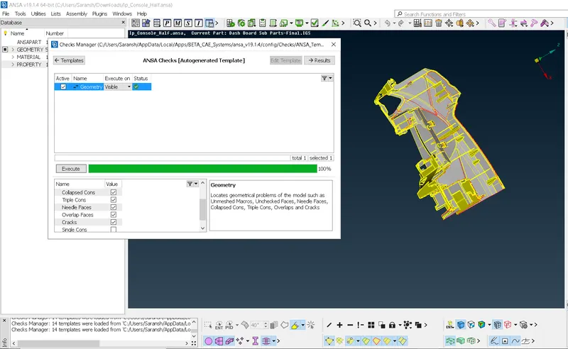
Finally, the model is checked for geometrical errors in the check manager. If any errors in triple/single cons arise, ANSA in most cases would be able to clear it using the FIX command. IF the model passes for topology cleanup the following image is displayed.
To perform geometric checks, Checks - Geometry - Select required params
Midsurface Extraction:-
Meshing:-
Meshing is a very integral part to construct the Finite element model. Meshing is the process of discretization of the CAD model into a so-called 'Finite-Element model or FE model'. Meshing is one of the core processes which makes the Finite element method possible, as it helps us convert a continuous problem with an infinite number of points into a discrete set of elements which then can be computed for the field variable and integrated over the whole domain.
A well-structured mesh affects the accuracy of your result, computational time, convergence. While a lot of commercial pre-processing and solver bundled CAE software packages do allow the users to tweak the type of mesh they require, yet they are limited. While a few others (like ANSA and HYPER MESH) are more flexible than they allow users to fully customize their meshed FE model while mitigating errors through a clean GUI.
structured mesh affects the accuracy of your result, computational time, convergence. While a lot of commercial pre-processing and solver bundled CAE software packages do allow the users to tweak the type of mesh they require, yet they are limited. While a few others (like ANSA and HYPER MESH) are more flexible than they allow users to fully customize their meshed FE model while mitigating errors through a clean GUI.
________________________________________________________________________________________________________________
MESH PARAMETERS AND QUALITY CRITERIA
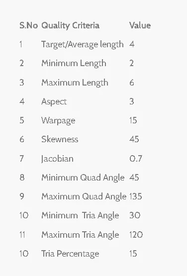
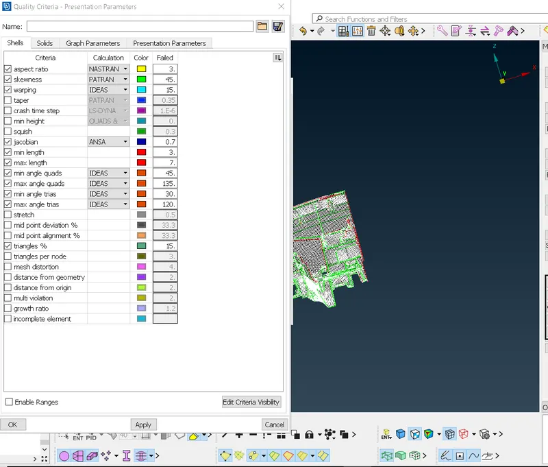
Prior to meshing the user has to define the required mesh parameters. ANSA tries to follow this input data to give a more precise mesh. In the mesh parameter popup box, the average length of each mesh element is specified along with the limits (i.e min and max target length).
Moreover, the type of mesh element (quad/tria/ortho tria) and the element order (1st/2nd order) can also be defined in the parameters tab. This can also be changed during any mesh generation command or even during the mesh refinement process.
Learning:-
- There were many errors faced during meshing and many times redone.
- After geometry cleanup performing meshing was a hard task, many times meshing was with a lot of OFF elements, and performing the quality criteria was a great task to learn different aspects of meshing.
- Performing meshing for different parts also made great advancements in learning new concepts of this preprocessor and also got to know new features.
Conclusion:-
- Geometry cleanup was performed.
- Thickness measurement was performed.
- Mid surface extraction was taken
- Meshing was performed with the use of different tools.
- A quality criteria check was performed and removal of off elements was done.
- Shell as solid
References:-
https://enterfinite.com/blog/f/a-beginners-guide-to-mesh-generation-using-ansa?blogcategory=General