Project 1 - 2D meshing on the instrumental Panel
AIM:
- To do a pre-processing on a given model using ANSA.
OBJECTIVE:
- To check the geometrical error on the given models.
- To extract a mid-surface of the given models.
- To generate 2D mesh on the components based on the quality criteria given.
- Assigning thickness to the components.
PROCEDURE:
IMPORTING THE CAD MODEL:
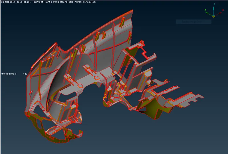
- The CAD model is imported into the workspace by using file > open and select the CAD model.
- The model will be imported into the workspace.
- In ANSA we can import all types of CAD software file formats.
GEOMETRY CLEANUP:
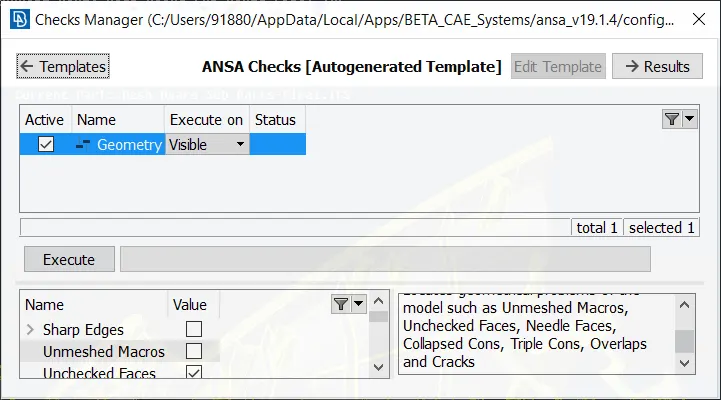
- Before working on the model we need to check whether the model has any geometrical errors.
- To check the geometrical errors go to check manager that is available at the tool bar.
- In the check manager select geometry and click execute.
- After clicking on the check geometry the geometrical errors will display.
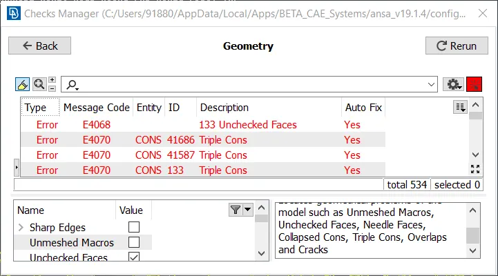
- The geometrical errors can be fixed manually or automatically.
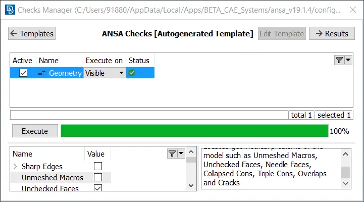
- In our case we fixed the error automatically by right clicking on the error and click fix.
- Once the model has no error it will show green status in the above image and we can proceed further.
MIDSURFACE GENERATION:
FOR BIGGER AREA:
- For extracting Mid surface various tools like Faces > offset, Faces > middle, Faces > mid surface > casting are used to create mid surface automatically and manually.
- The automatic mid surface extraction is not working in this case due to complex features present in the model.
- So in this case manual mid surface extracting tools like offset and middle is used.
- To extract mid manually go to faces > offset
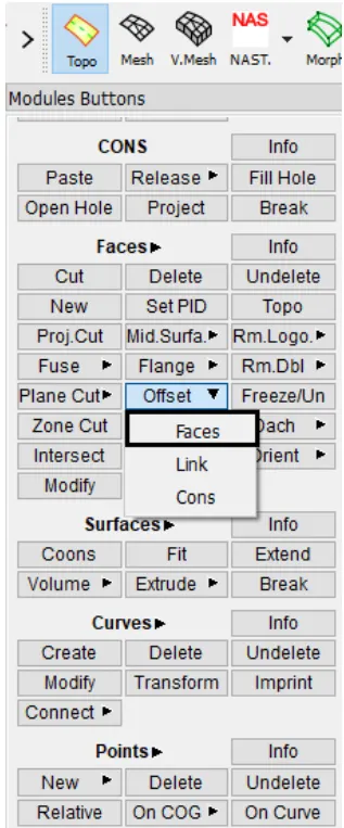
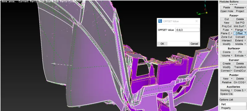
- Select the component faces and give the offset value and click middle mouse button.
- This will convert the solid model into a thin shell components.
- Then the mid surface is extracted by using AND and INOT tools available in ANSA
FOR SMALL RIBS:
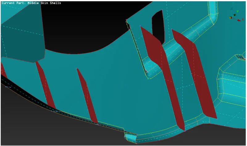
- The middle option is used on both sides of the rib. Then a midsurface will be formed.
FOR LONGER RIBS:
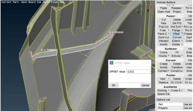
- The midsurface for longer ribs is generated using a faces > offset and the value is given in the desired direction.
- Then the midsurface of long rib is extend to the bigger mid surface.
FOR DOGHOUSE:
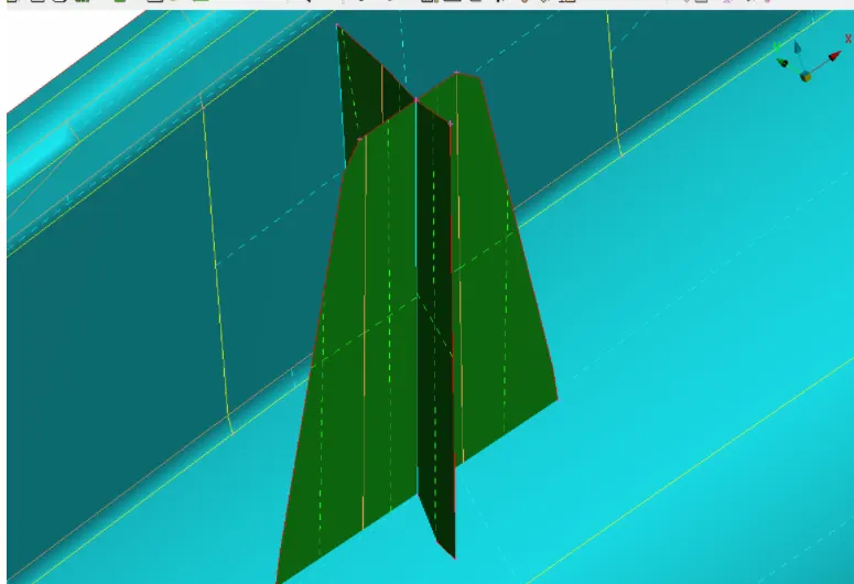
- The doghouses are captured as two intersecting rectangular ribs.
- Using cons2curve option the curve on the cylindrical feature of parent geometry and the rib is connected using faces > new > fitted surface option.
- Similarly create mid on other side. After creating surfaces on both sides extend all the required surfaces to the main mid surface and the intersect option is used to form triple con in the middle.
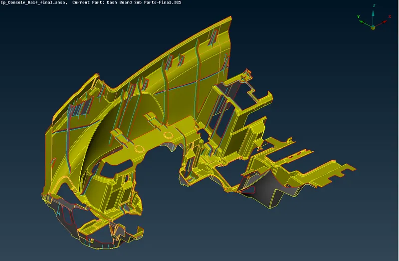
- The final midsurface model will be look like as shown below.
PROPERTY ID CREATION:
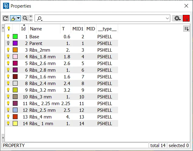
- Then the property id is created for the mid parts by going to set PID and select the surface and give the thickness value and click ok.
- Then go to property id manager and right click the PID and click apply.
2D MESHING:
QUALITY CRITERIA:
- Go to quality criteria that is available in tool bar.
- The criteria that is given in the question are selected and given the value and clicked apply and ok.
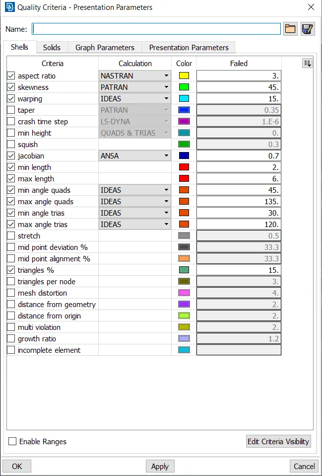
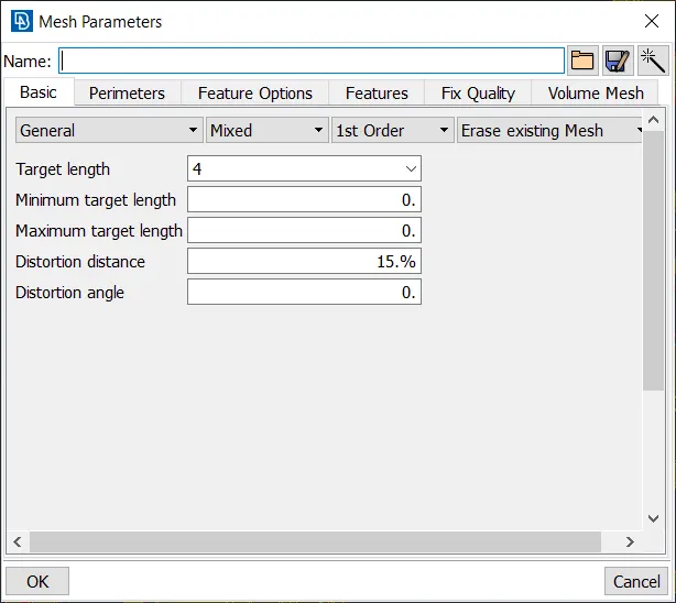
- Then the values of mesh parameters are entered.
- For that go to mesh parameter tool that is available in the tool bar of ANSA.
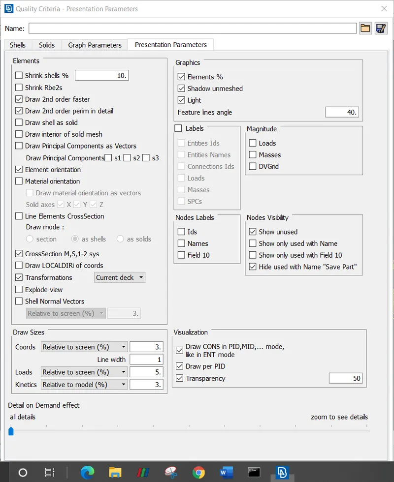
- To enable the total percentage of trias and the quality of the off elements we are selecting element percentage in presentation parameters. After that select all details and click apply to obtain the total values of elements and trias percentage of the total model.
- Then the meshing is done using mesh generation > spot mesh tool. This tool generates the mesh.
- Then the created mesh is refined using the shell mesh > improve > reconstruct, smooth, reshape tool in mesh module of ANSA.
- It is ensured that there are no rotating quads.
- The trias are kept as low as possible.
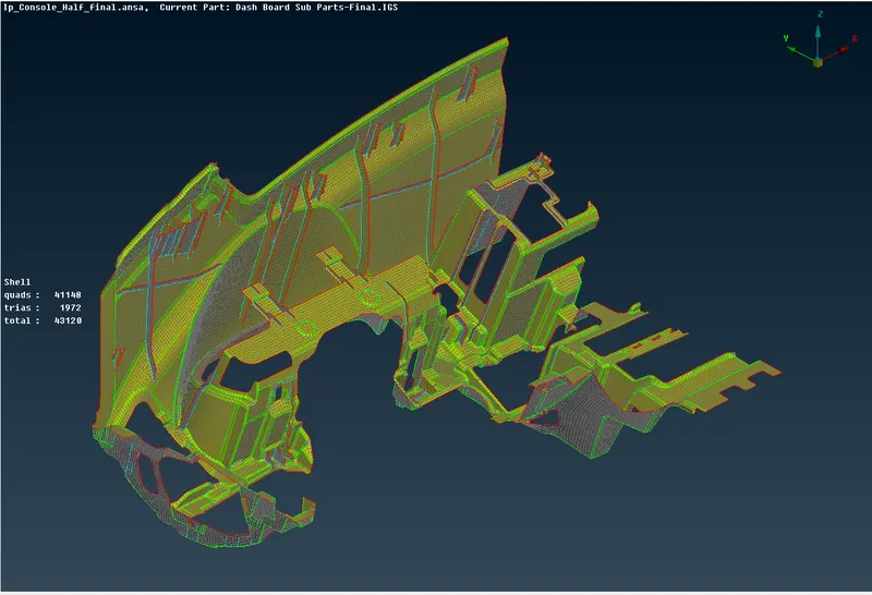
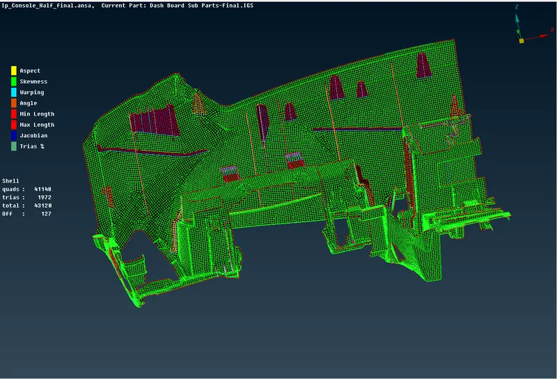
- Finally after creating the mesh and clearing the quality criteria the shell element representation is changed by going to utilities> quality criteria> presentation parameters and enabling the draw shell as solid.
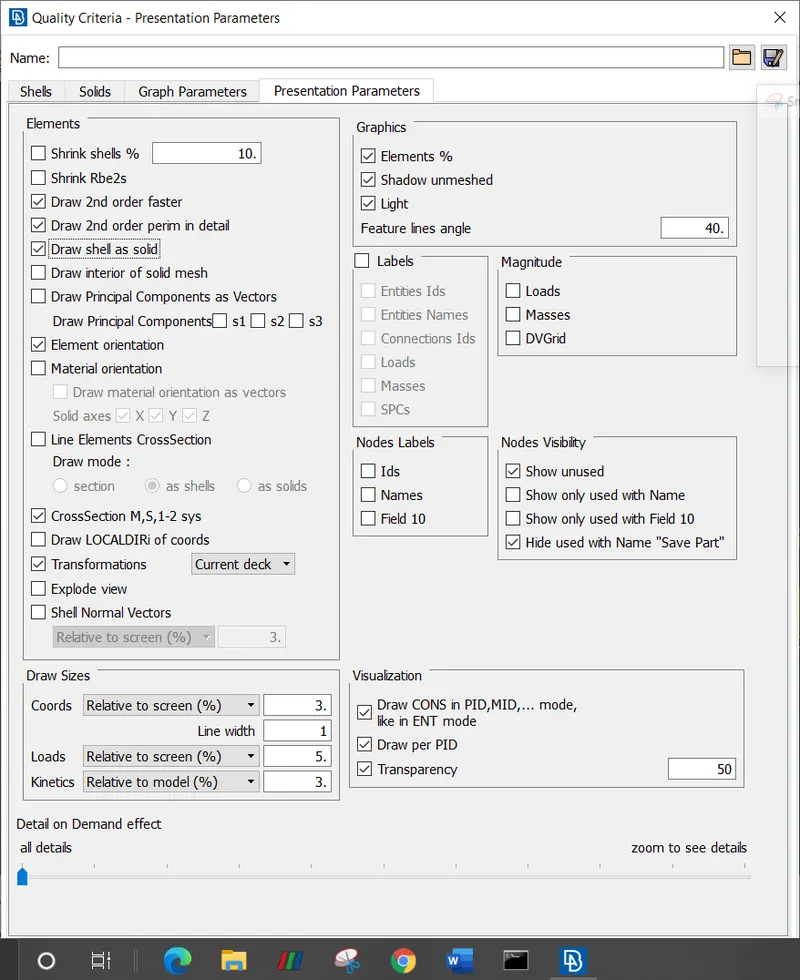
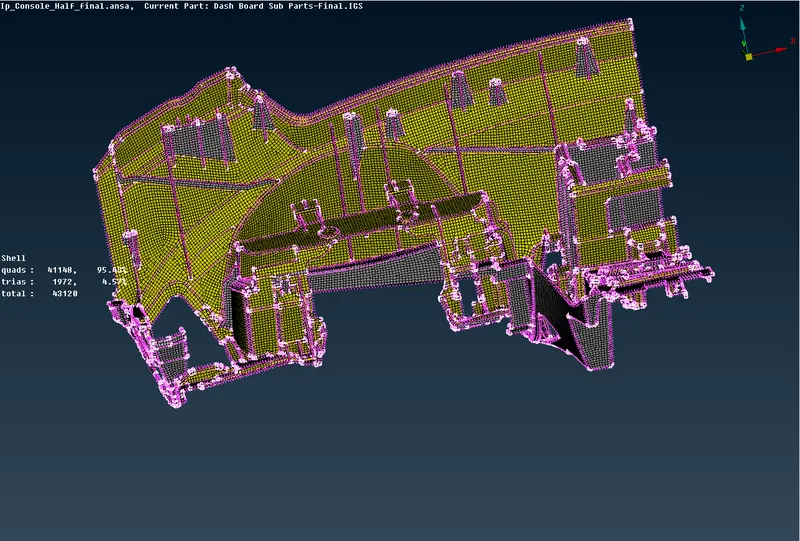
- Draw shell as model will add thickness to the model with the thickness that is provided in property ID.
- Then the final model will look like the image as shown below.
RESULT:
- Hence the mid surface has been extracted from the parent geometry.
- Ensured there are no surface deformations in the geometry.
- A well connectivity has been established between surfaces.
- The features have been captured properly.
- A good mesh flow has been achieved.
CONCLUSION:
Geometry cleanup, mid-surface extraction and 2D meshing of the given models were successfully done.
MODEL LINK:
https://drive.google.com/file/d/1FWDItpd8GQCsTq2zalkpcHK40UrGiw8z/view?usp=sharing