Project 1
Project 1
Engine Wire Harnessing
Objective:- To route the wire harnessing for engine, create flattening model & create drawing for given routing.
Description:-
Step 1:Electrically define the connectors, P clamp & Guiding component.
Connectors:
Steps involved in electrically defining a connector
- Download a connector from TE / Tyco website igs or stp format.
- Unzip the connector in destination folder.
- Save as CAT part in the folder
- Rename geometrical set as Reference element
- Define reference elements such as bundle connection point, connector connection point, cavity connection point by taking the between option in the point command with middle option.
- Bundle Connection Point.
- Cavity connection Point
- Define the axis of the connector connection point & Bundle Connection Point. The Y-axis should be normal to the face, x in the horizontal direction to the base plane & Z is vetical to the base plane as per the connection provided to the mating part for the smooth electrical connection.
- Enter into electical part design workbench & define a connector with the given number of Terminals.
- Bundle Connection point definition
- Cavity connection Point Definition
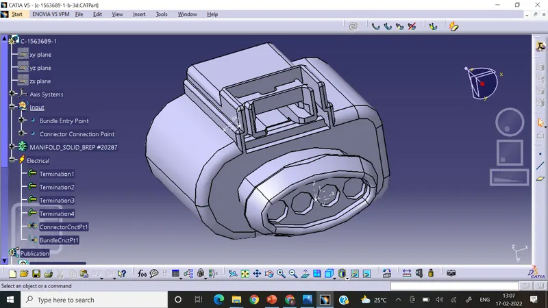
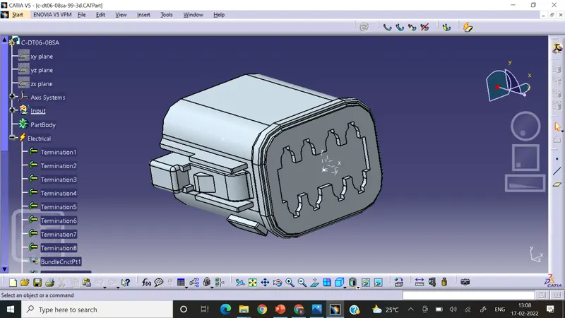
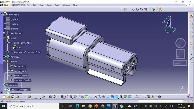
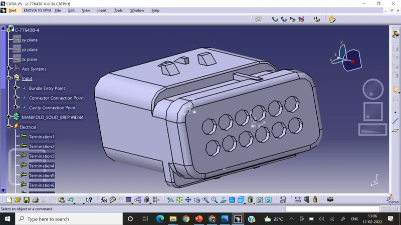
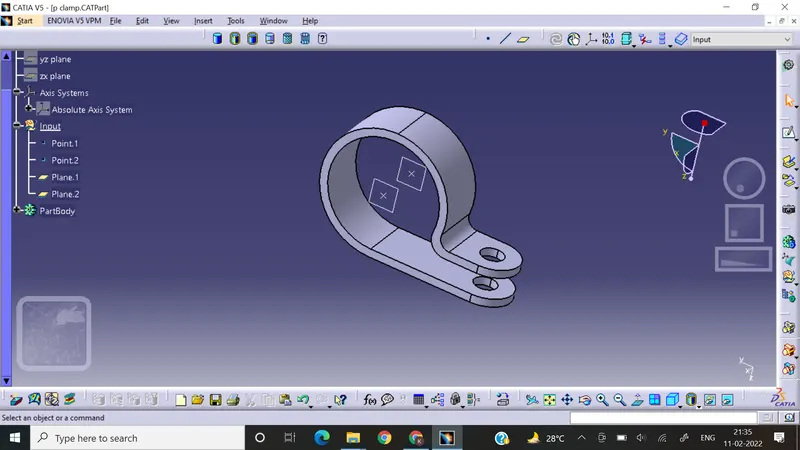
P-Clamp Definition:
- Take a plane at the centre of circle parallele to the vertical direction on both sides.
- Then take a plane at the base.
- In the electrical part design define it as as support'
- Define entry & exit from both the sides for easy electrical connection.
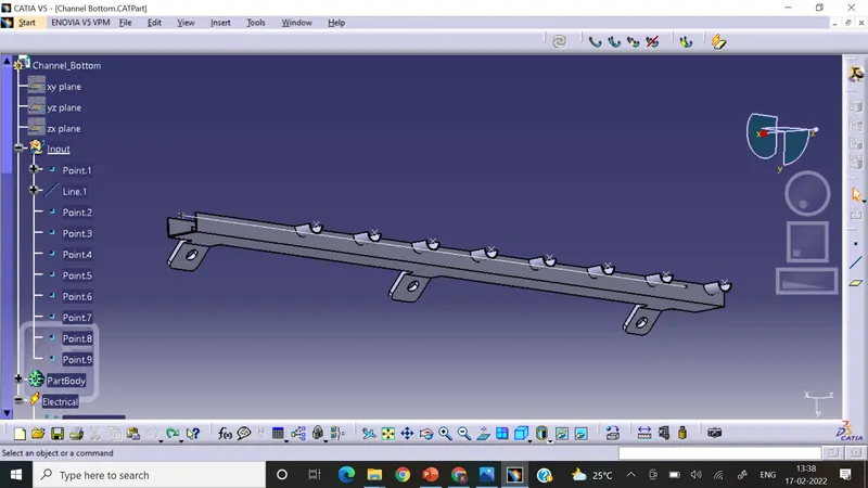
Guiding Channel Definition:
- Take the two points in the centre of the two ends of the channel.
- Then draw a line connecting those two points.
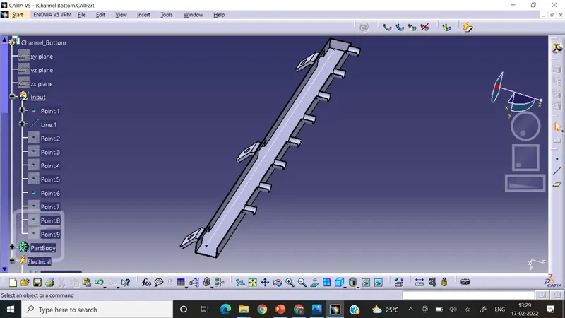
- Create the centre point at every bundle entry channel.
- Define as mounting suppport to the channel.
- Define the bundle entry point at channel start point & every entry point.
Step 2: Create a context assembly which will be helpful to contain reference parts along with the geometrical bundle assembly.
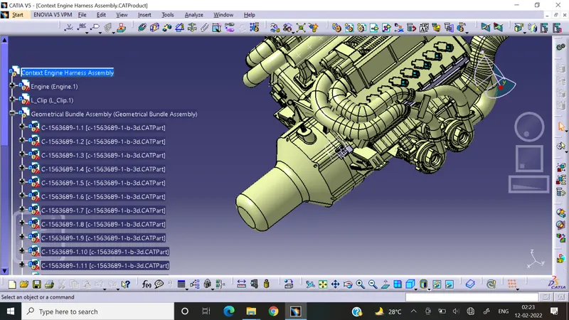
Step 2: add engine product in the context assembly.
Step 3: Create engine harness geometrical bundle assembly.
Step 4: Position connectors using the manipulation, smart move & Compass on the sockets given in the engine.
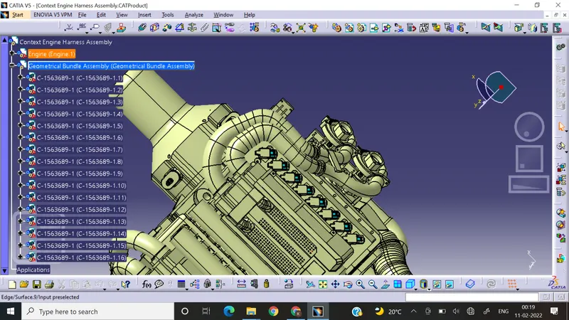
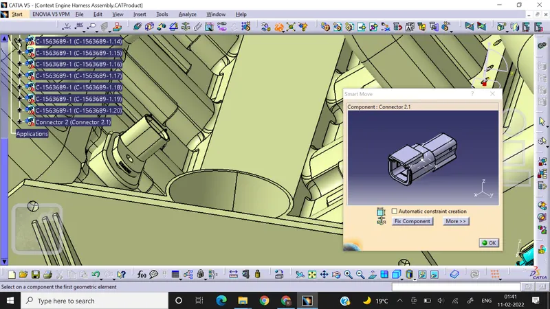
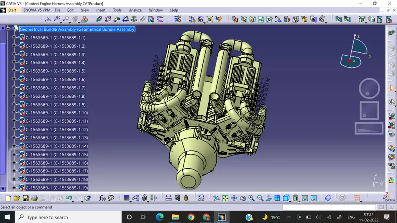
Step 5: Add the L-Clamp for the interconnector.
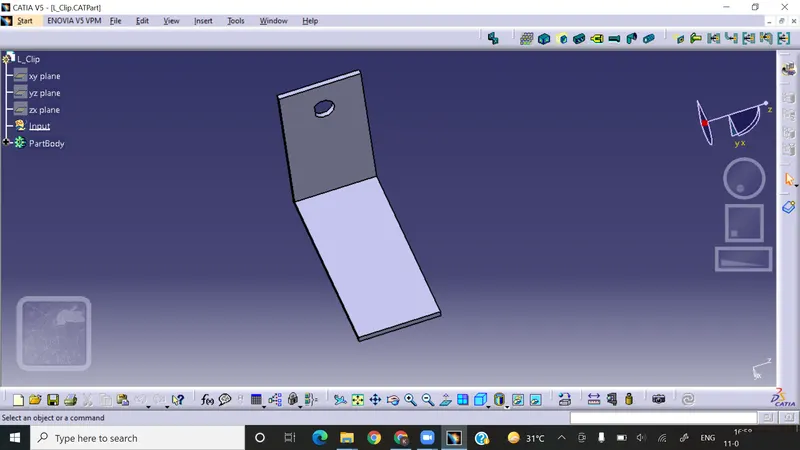
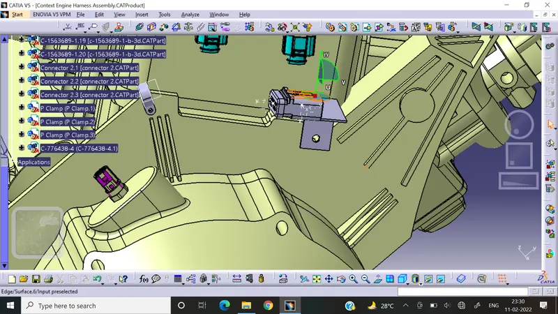
Step 6: Routing the wiring according to the connections
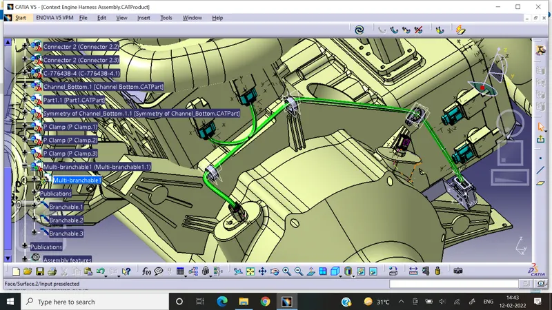
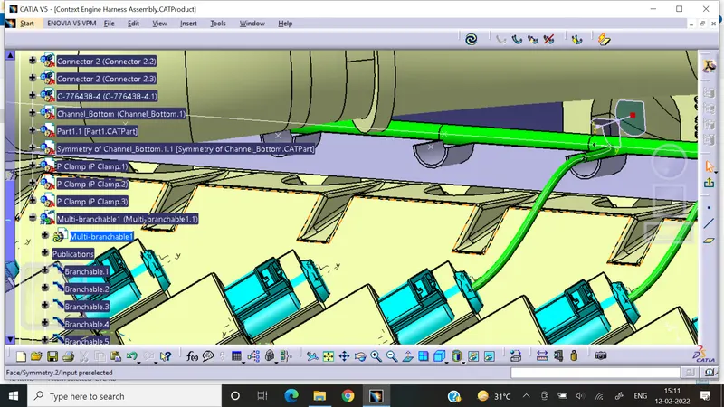
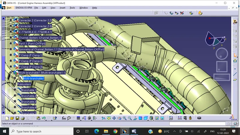
Step 7: Application of COT tubes wherever required according to the bundle diameter for protecting wiring from hot components such as engine parts.
Step 8: Check the continuity among the routing.
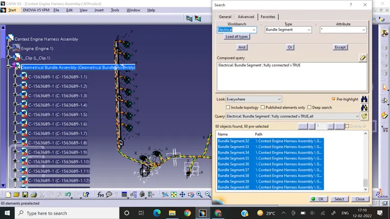
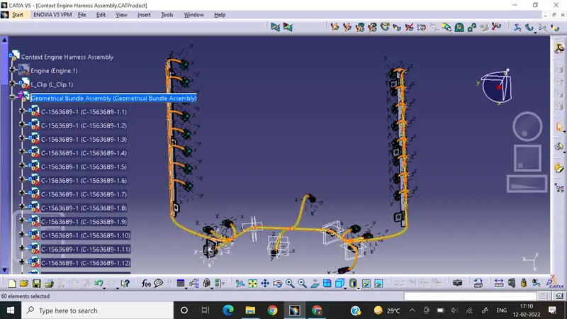
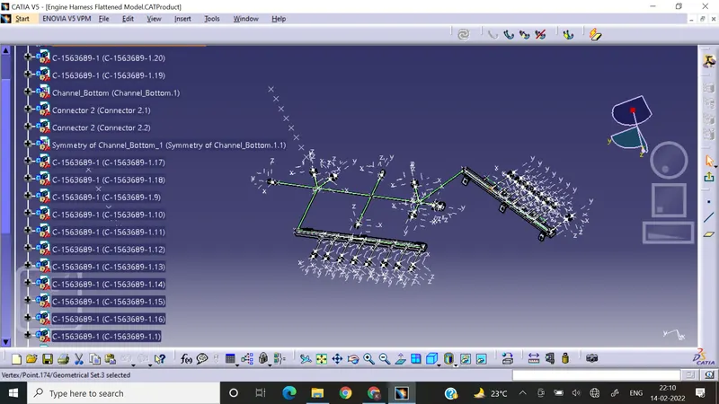
Step 9: Flattening model:
- Create a new Product
- Define the Flattening parameters
- Extract geometrical bundle.
- Use the flattening option.
- Rotate or manipulate the components along the required plane.
Step 10: Create a Drawing product & create a drawing.
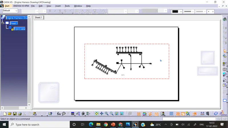
Conclusion: In this way I have completed all wiring harness, flattening & drawing for the given wiring harness of a engine.