Project 1
Project 1: Creation of Mold for a table fan outer casing
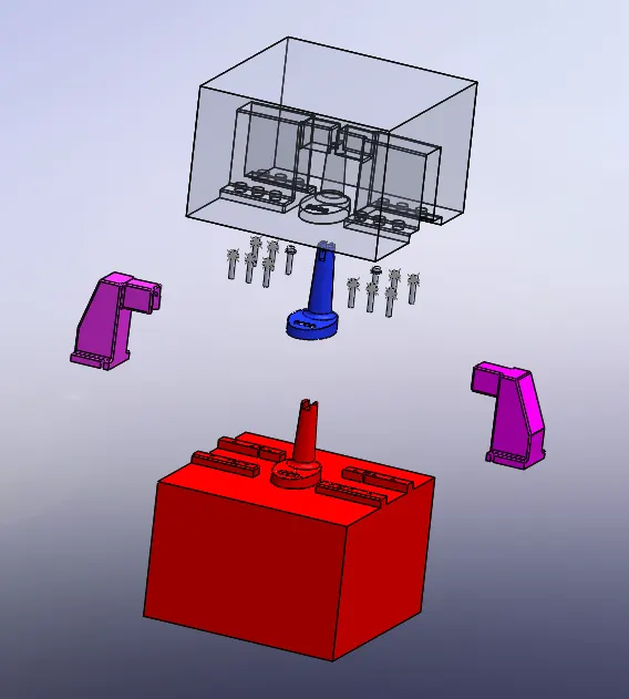
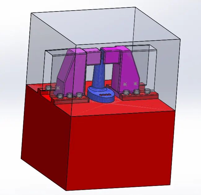
Fig_1:Table Fan Casing Mold Design.
Objective: Creation of fan outer case mold design using solidworks.
Introduction:
- Injection molding involves heating & injecting the plastic material under pressure into a closed metal mold tool.
- After the sufficient cooling cycle the material gets solidified as per the required shape.
- Then the mold is opened & the required component is processed for the next usage.
- Injection moulding is a manufacturing process for producing parts by injecting molten material into a mould.
- Injection moulding can be performed with a host of materials mainly including metals for which the process is called die-casting
- Glasses, elastomers, confections, and most commonly thermoplastic and thermosetting polymers.
Working:
- Initially the mold is made by the mold maker as per the specified dimensions of the required component with accuracy to get the good quality component.
- After that the elevated temperature plastic material is poured into it & after the completion of cooling cycle the material gets solidified.
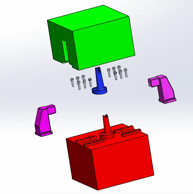
- Then the the mold is opened sliders & ejecter pins are removed.
- The given component is ejected out after all this process.
Methodology:
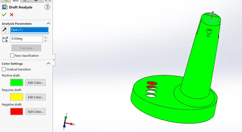
- Step_1: Draft analysis
Draft analysis is executed to make sure the sufficient drafts are given to the given component. If sufficient drafts are not given then there will be problem occurs at the removal of the solidified component. The components where draft is missing is applied in this step & then the draft analysis is conducted again at 0.5 degrees.
Step_2: Scaling
Every mateial having some shrinkage properties. To cater with the shrinkage problem the scaling allowance is provided for the materials. In this project the ABS material is used which is having shrinkage allowance of 0.6%.
(0.6/100)+1=1.006 is the scaling provided to the given component.
Step_3: Parting Line
The parting line divides the core & cavity into two parts.
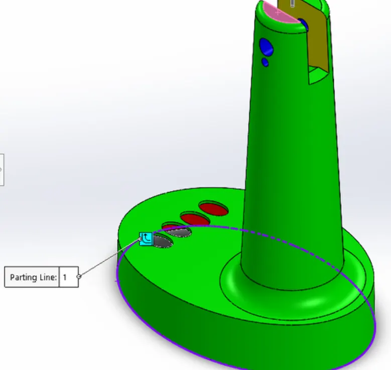
Step_4: Shut Off Surfaces
Shut off surfaces command is used to cover the holes in the given component. The hole should be covered to divide it into core & cavity.
Step_5: Parting surface
The parting surface command is used to create the parting surface for the given component.
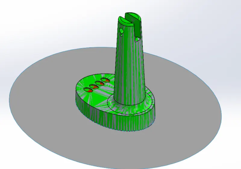
Step_6:creating core cavity surfaces
- The copy of the parting surface is created using move/copy command from direct editing
- Then the knit suface command is used to get the two different surfaces as core surface & cavity surface.
Step_7:Open core cavity in assembly.
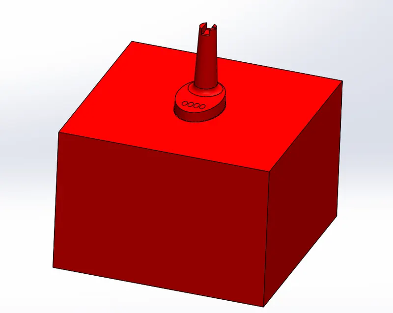
Step_8: Core block creation
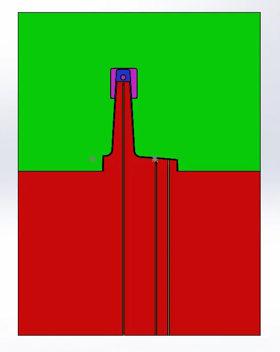
- The rectangle is drawn on the core surface & it is extruded to get the core block.
- Then the cut with surface command is used to get the core block.
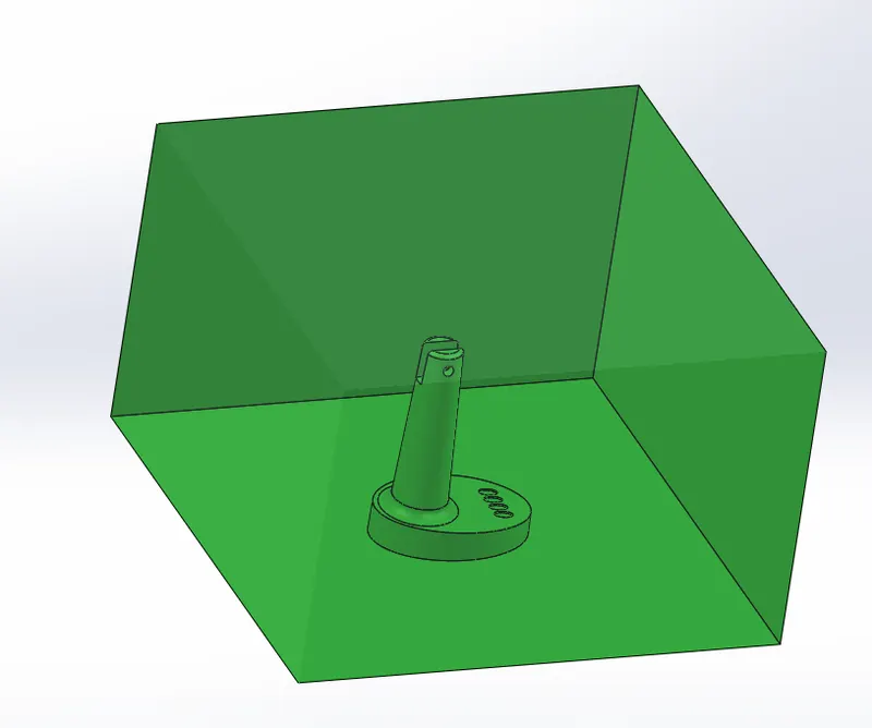
Step_9: Cavity block creation
- By using the previous core block sketch is used using convert entities command & then extruded.
- Then by using cut with surface command we can get the cavity block.
Step_10: Ejector Pins
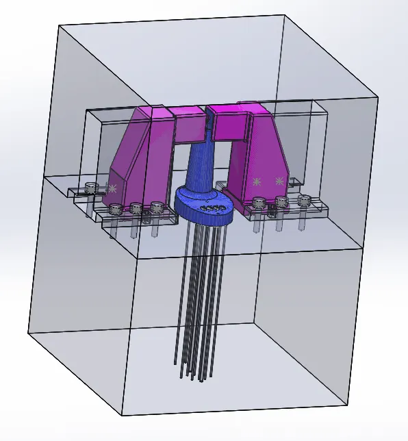
Ejector pins helps the component to be removed safely from the mould.
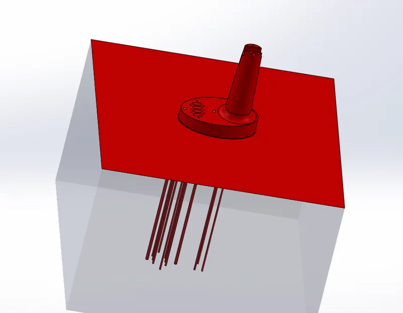
Step_11: Created reliefs for the ejector pins.
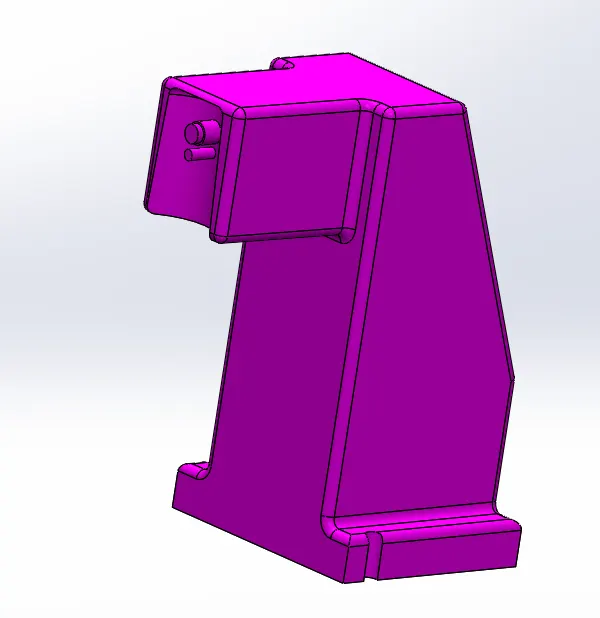
Step_12: Sliders
- Undercuts present in the components creates problem for the ejection of the part from mould.
- For the easy removal of the component the sliders are provided for the mould.
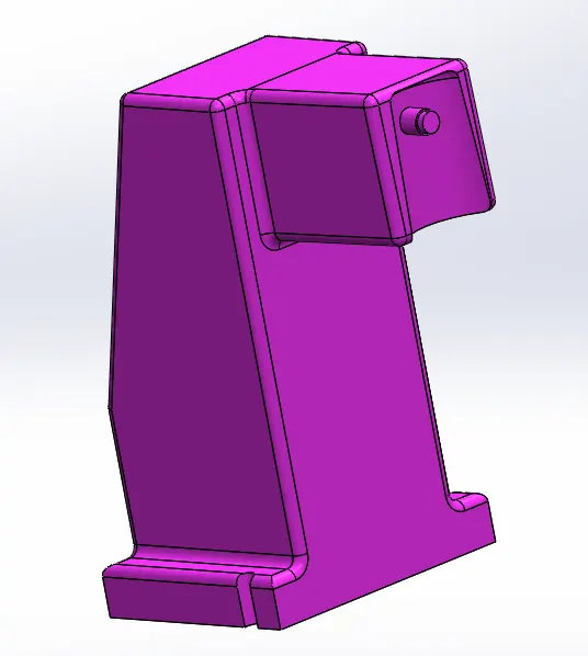
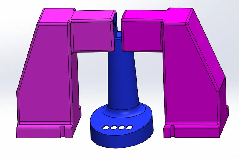
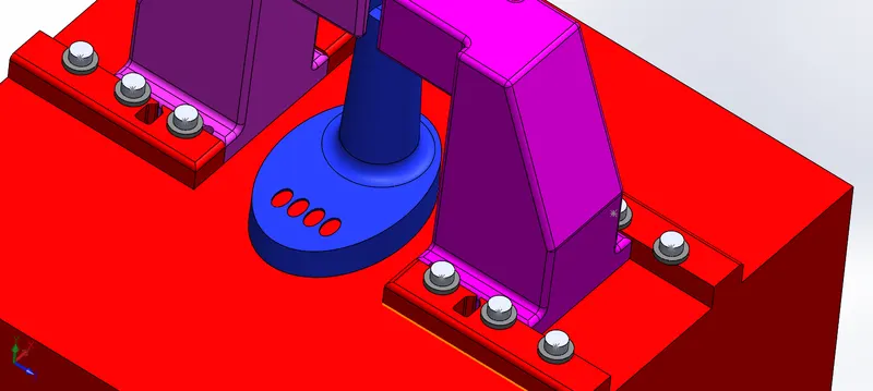
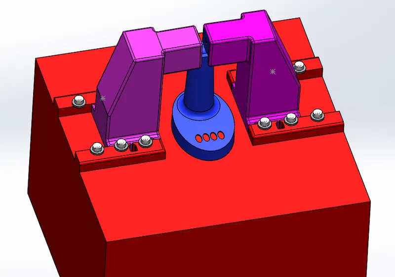
- There are holes present in the table fan outer casing so we have provided two sliders one for two holes in left side & the another for remaining one hole in right side.
- The sliders are created using the split command & creating the sketch of the required shape of the slider.
Step_13: Washers & locking Mechanism

Result:
Hence, using the above methodologies we have designed the steel core & cavity with ejector pins & sliders using SolidWorks.