Project 1
Objective :
The objective of this project is to create the routing for the given Engine and prepare to flatten the view drawing in CATIA V the mechanical part as an electrical connector and apply the electrical properties to the Connectors.
Procedure :
Procedure for Connector Definition:
- Initially, the mechanical model of the required connectors is downloaded.
- After that, the downloaded source file (Stp/Igs) is converted into CAT Part.
- Connector Definition :
1) Create/Download Connector 3D
2) Create required Geometrical Parameters
- In the third step the required reference points like Bundling entry point, Connector connection point, and Cavity connection point.
- Also, the required axis system for the Connector and Cavity is created.
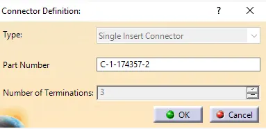
3) Define part as Connector
- The parts are defined as connectors by using the "define connector" option in CATIA
- While defining the connector, depending on the connector number of the terminal is mentioned.
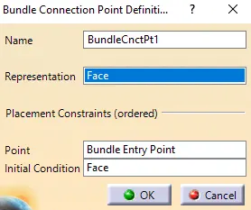
4) Define “Bundle connection point”
- The following parameters are defined for the "Bundle Connection Point"
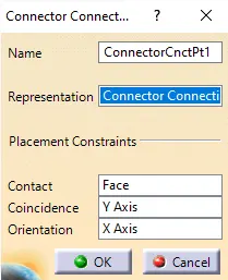
5) Define “ connector connection point”
- The following parameters are defined for the "connector connection point"
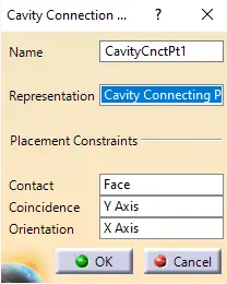
6) Define “ cavity connection point ”
- The following parameters are defined for the "cavity connection point"
- The cavity connection point is an optional one. For some components, we will use a cavity depending on the requirement.
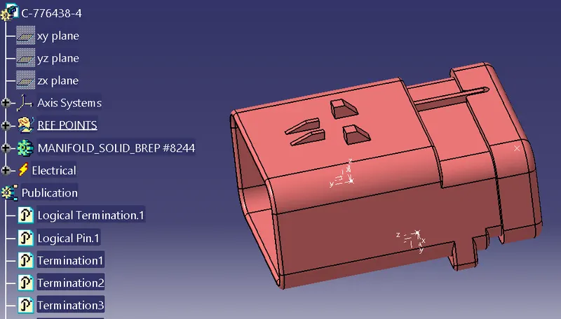
C-776438-4
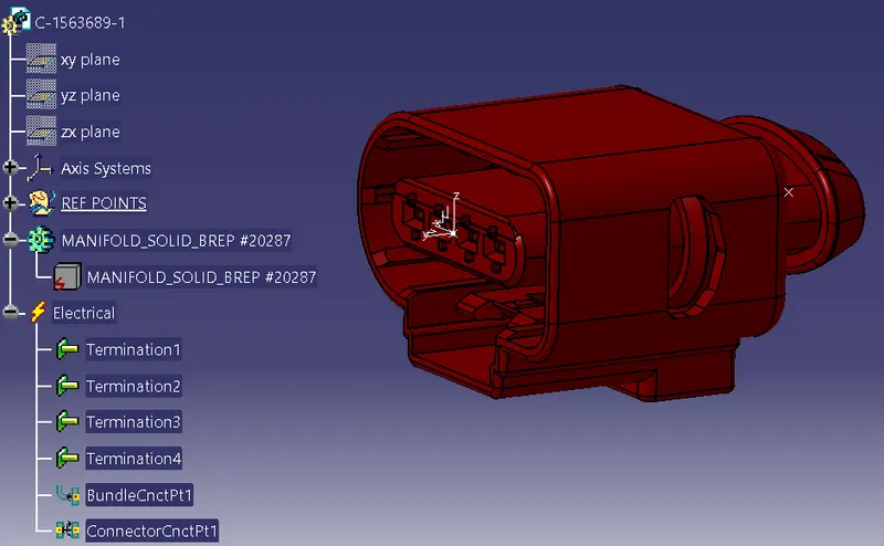
C-1563689-1
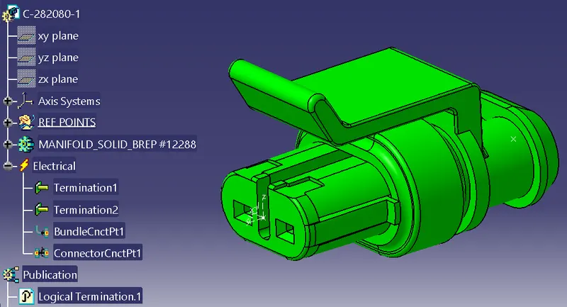
C-282080-1
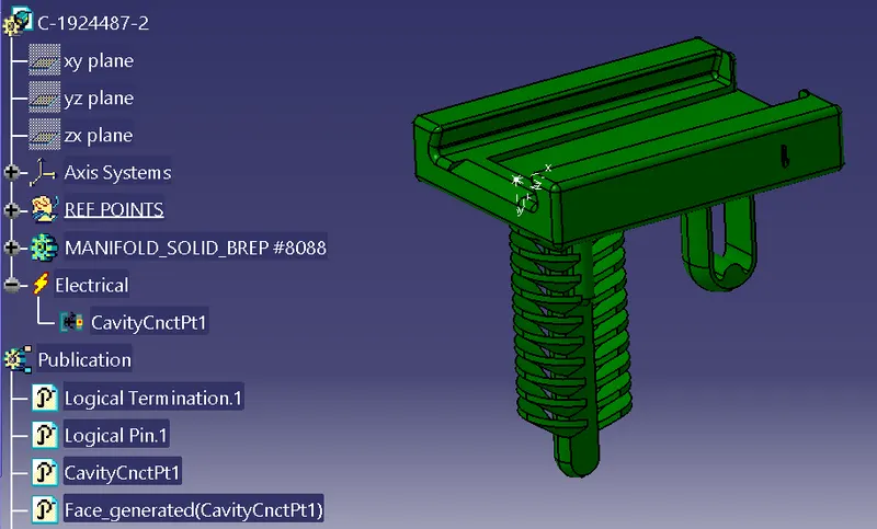
C-1924487-2
Procedure Clamp:
- Initially, the mechanical model of the required connectors is downloaded.
- After that, the downloaded source file (Stp/Igs) is converted into CAT Part.
- The geometrical parameters are applied to the electrical support.
- After that, the entry point and plane are selected for the clamps use "define support option"
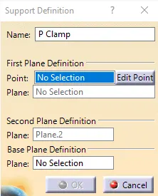
- Also, the base and exit planes are selected in the same way.
- The clamps will have 2 entry and exit points. Clamps are basically bi-directional.
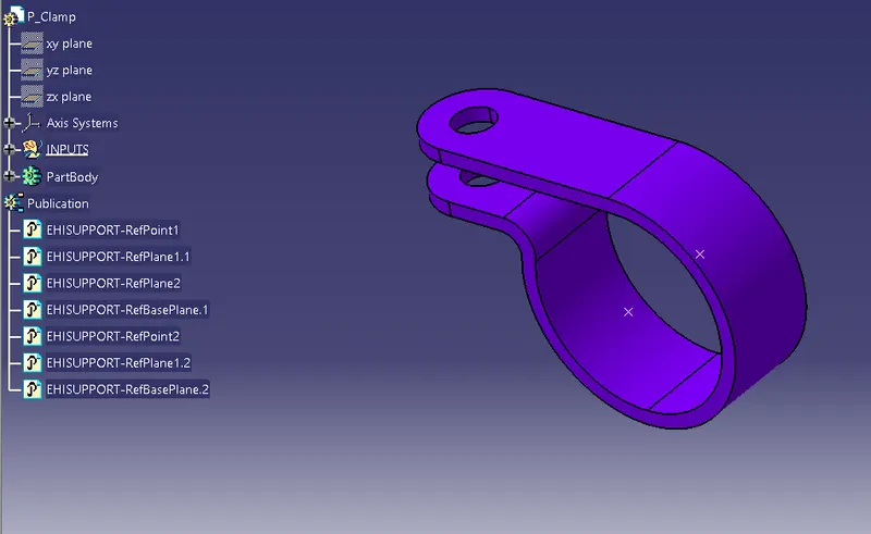
P-Clamp:
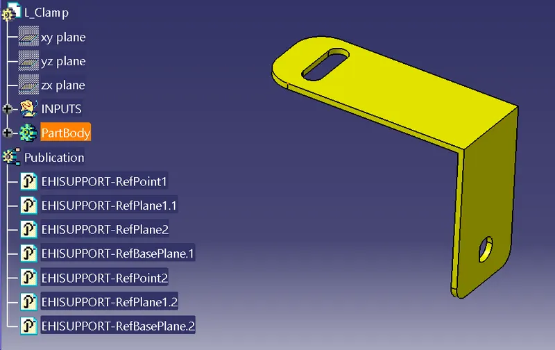
L- Clamp:
Procedure for Creating the Assembly Context:
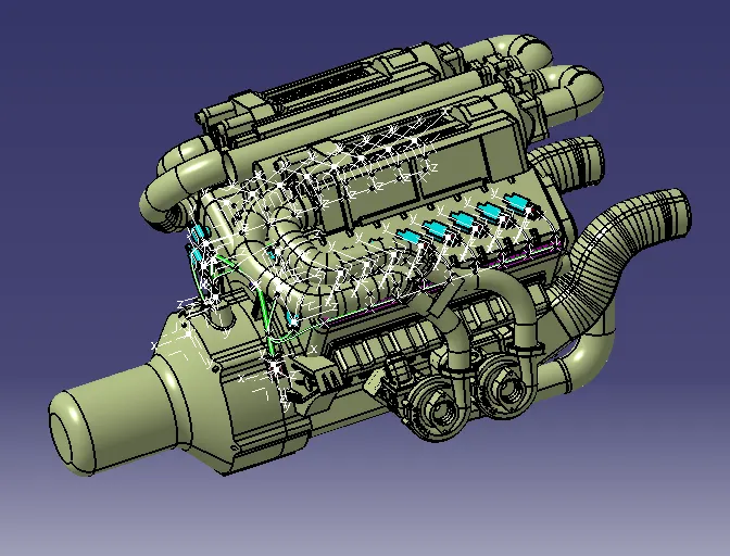
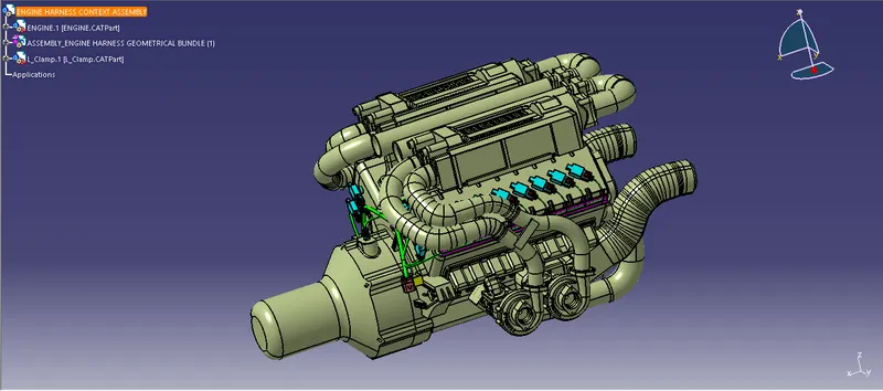
- Initially, the product is created that product consist of the Assembly of Geometrical Bundle and the Engine Reference part.
- Also, the reference clamps for the parts are inserted in the Context Assembly.
Procedure for Creating the Geometrical Bundle Assembly:
- The required connectors and the clamps are inserted in the assembly.
- After, that the models are placed in the required position.
- Once the models are placed in the proper place, the assembly is converted into the geometrical Bundle.
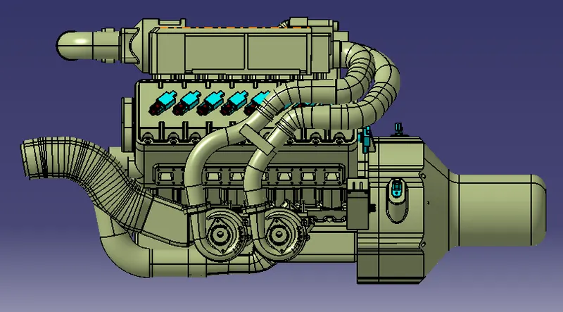
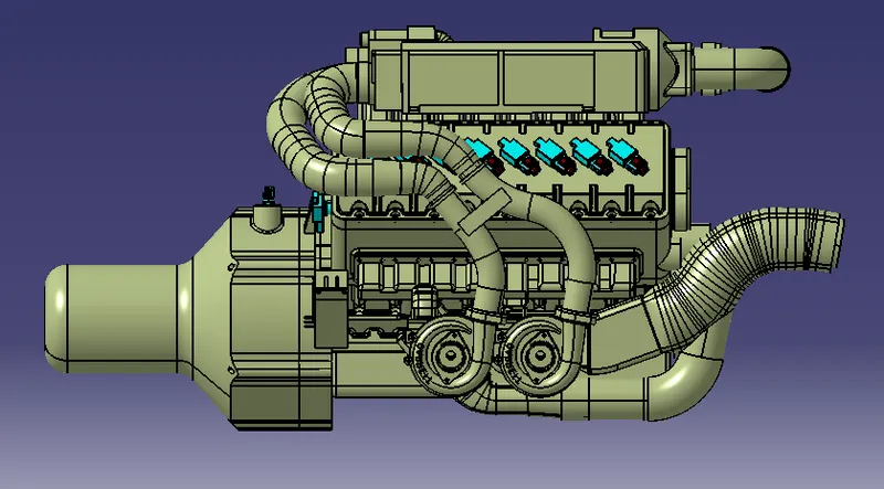
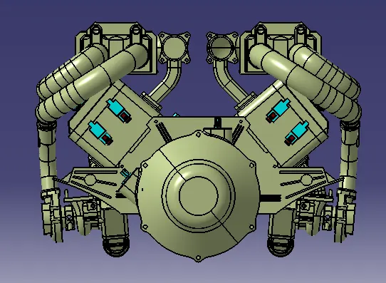
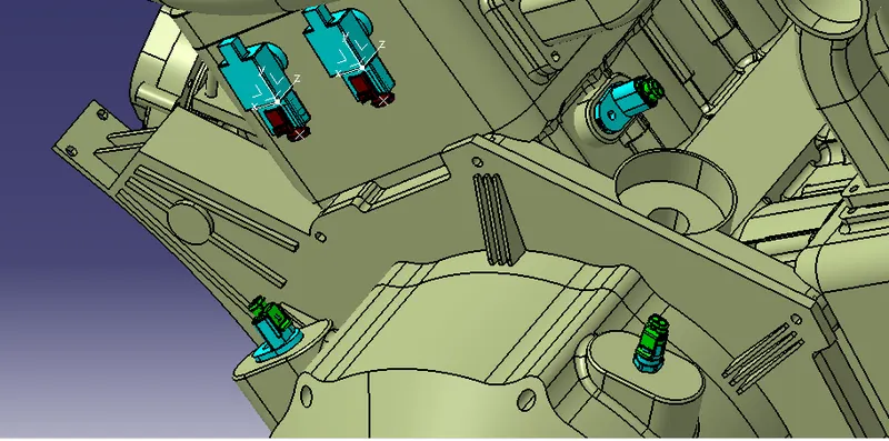
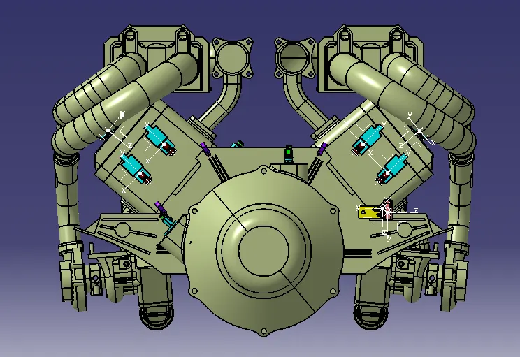
Procedure for Creating the Geometrical Bundle Assembly:
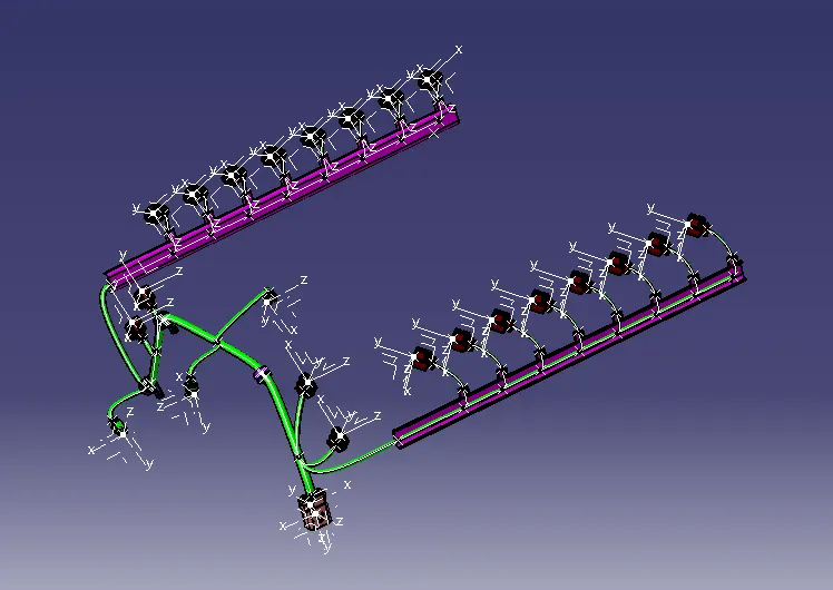
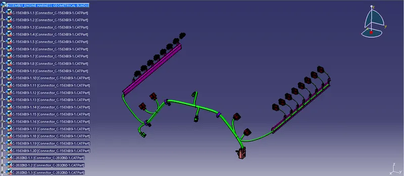
- In the geometrical Bundle, the multi Branchables are created.
- By using the bundle definition and then the bundle segment point the bundles in the required places are created.
Procedure for Checking the Bundle Connectivity:
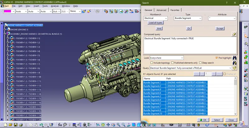
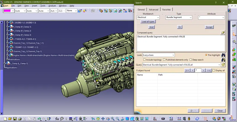
- The Bundle Connectivity is checked using the option called "search" available under the edit option.
Procedure for Creating the Flattening:
- The created geometrical bundle is converted into the Flattened Bundle by using the "Flatten" option available in the "Flattening Harness" workbench.
- Using the flatten the required parameters are created for the flattening assembly.
- After applying the parameters, by using the extract option the geometrical bundle assembly is inserted into the Harness Flattening Assembly.
- Finally, the flattened model is converted into Drawing by using the " Drafting" workbench.
Conclusion:
The Routing is created for the given model by using the different workbenches in CATIA like Part Design, Assembly Design. Electrical Part design, Electrical Harness Assembly, etc.