Project 1
Aim : Craft a wiring harness for the assigned V6 Engine within CATIA V5, ensuring compliance with packaging guidelines and industry standards learned in the course. Exhibit proficiency by integrating optimal practices into the design. Produce a flattened view drawing to document the harness layout accurately.
Introduction
A wiring harness is an organized assembly of wires and components used to transmit electrical signals. It simplifies installation and maintenance while protecting wires from damage. Harnesses are vital in vehicles, machinery, and electronics, ensuring reliable electrical connections. They vary in complexity but adhere to specific requirements for functionality and safety.
Engine Harness
An engine harness, also known as an engine wiring harness, is a specific type of wiring harness designed to connect the various electrical components of an engine to the vehicle's main electrical system. It typically includes wiring for components such as fuel injectors, sensors, ignition coils, and the engine control module (ECM). Engine harnesses are crucial for the proper functioning of the engine and must be designed to withstand the harsh conditions found within the engine compartment, including high temperatures, vibration, and exposure to fluids.
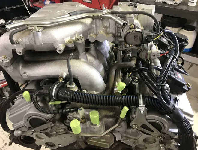
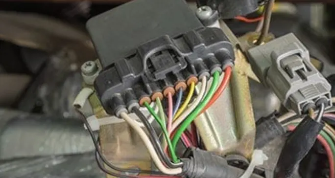
The engine wiring harness serves as the central nervous system of a vehicle's electrical system, facilitating the transmission of power and control signals to various components. Here's how it works:
How works harness system
1. Power Distribution: The wiring harness receives electrical power from the vehicle's battery or alternator and distributes it to different parts of the engine and other electrical components throughout the vehicle.
2. Signal Transmission: It carries control signals from the vehicle's computer systems (such as the engine control module) to sensors, actuators, and other devices. These signals regulate functions such as fuel injection, ignition timing, and emissions control.
3. Interconnection: The wiring harness connects individual electrical components within the engine compartment, as well as components located elsewhere in the vehicle. This includes sensors, switches, relays, solenoids, and motors.
4. Protection and Organization: The harness is designed to protect the wires from damage due to heat, vibration, moisture, and other environmental factors. It also organizes the wires neatly to prevent tangling and interference.
5. Integration with Vehicle Systems: The engine wiring harness integrates with other vehicle systems, such as the lighting system, audio system, and HVAC (heating, ventilation, and air conditioning) system, to ensure seamless operation of all electrical functions.
6. Diagnostic Capability: Modern engine wiring harnesses often include diagnostic features that allow technicians to troubleshoot electrical issues more easily. This may include built-in connectors for accessing diagnostic codes and test points.
Overall, the engine wiring harness plays a crucial role in ensuring the reliable operation of a vehicle's electrical system. It must be carefully designed and manufactured to meet the specific requirements of the vehicle's make, model, and engine configuration.
Objectives
1. Electrical Definition and Cataloguing: Define the electrical properties of all mechanical connectors and catalog them for reference.
2. Placement of Connectors on Engine Model: Position all connectors accurately on the provided 3D CAD model of the engine.
3. Application of Mounting Hardware: Place P-Clamps and Fir Tree clips according to packaging rules and positioning requirements.
4. Routing of Wiring Harness: Design the routing of the wiring harness, incorporating the defined connectors and mounting hardware.
5. Creation of Branching Points: Establish branching points as necessary for sub-branches and connection to various connectors within the bundle.
6. Application of Protective Coverings: Apply appropriate protective coverings to safeguard the wiring harness as needed.
7. Creation of Flattened Wiring Harness: Generate a flattened representation of the wiring harness to finalize the geometrical bundle.
8. Drawing Sheet Creation: Utilize the drafting workbench to produce a drawing sheet featuring the flattened wiring harness for documentation purposes.
DESIGN METHODOLOGY
Step 1- download the engine CAD data and required connectors CAD data from the given source.
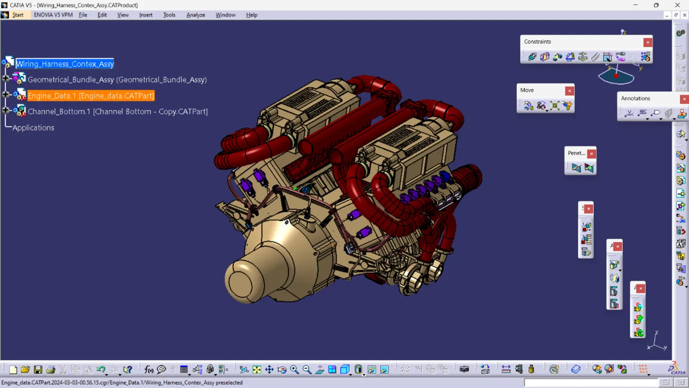
Step 2- Download the required Connectors from the source and convert the mechanical connectors electrically by using the electrical part design work bench by following below steps.
1. Begin by downloading the connectors and mounting clips from the provided link source.
2. Access the mechanical part workbench to establish the necessary geometric parameters. Create connector connection points and bundle connection points on the specified sides of the CAD part.
3. Define an axis system for each connector connection point. Ensure that the Y-coordinate aligns perpendicular to the connector face, the X-coordinate aligns towards the locking mechanism, and the Z-coordinate aligns upward.
4. For connectors with cavities intended for mounting clips, generate cavity connection points.
5. Utilize the established geometric parameters to execute the following:
- Define each part as an electrical connector.
- Establish bundle connection points.
- Specify connector connection points.
- Set up cavity connection points for connectors designed with mounting clip cavities.
Adhere meticulously to these steps to ensure accurate integration and functionality within the electrical system.
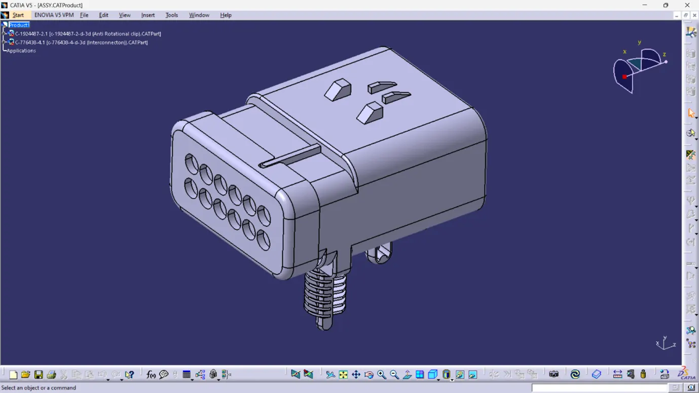
12 pole interconnection connector
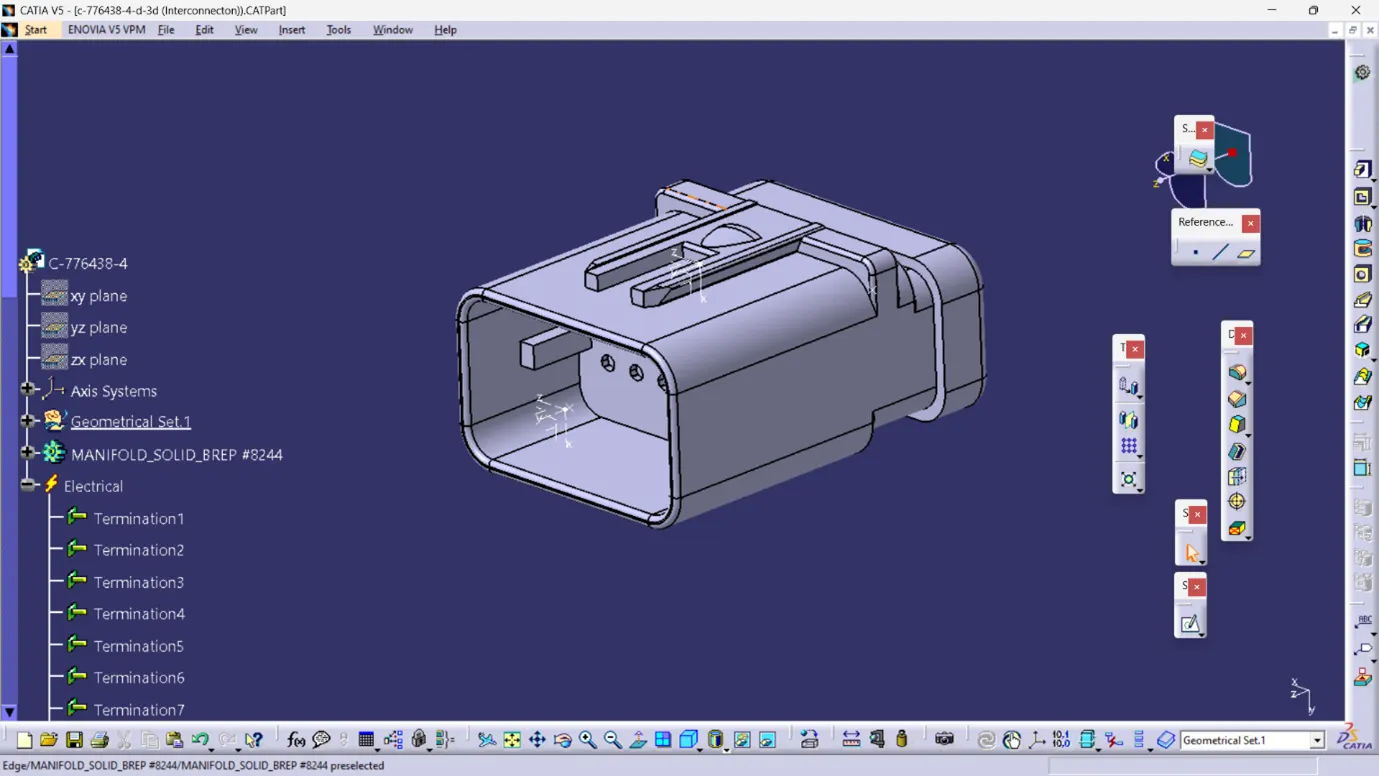
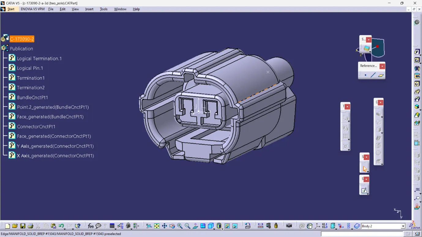
2 pole connector
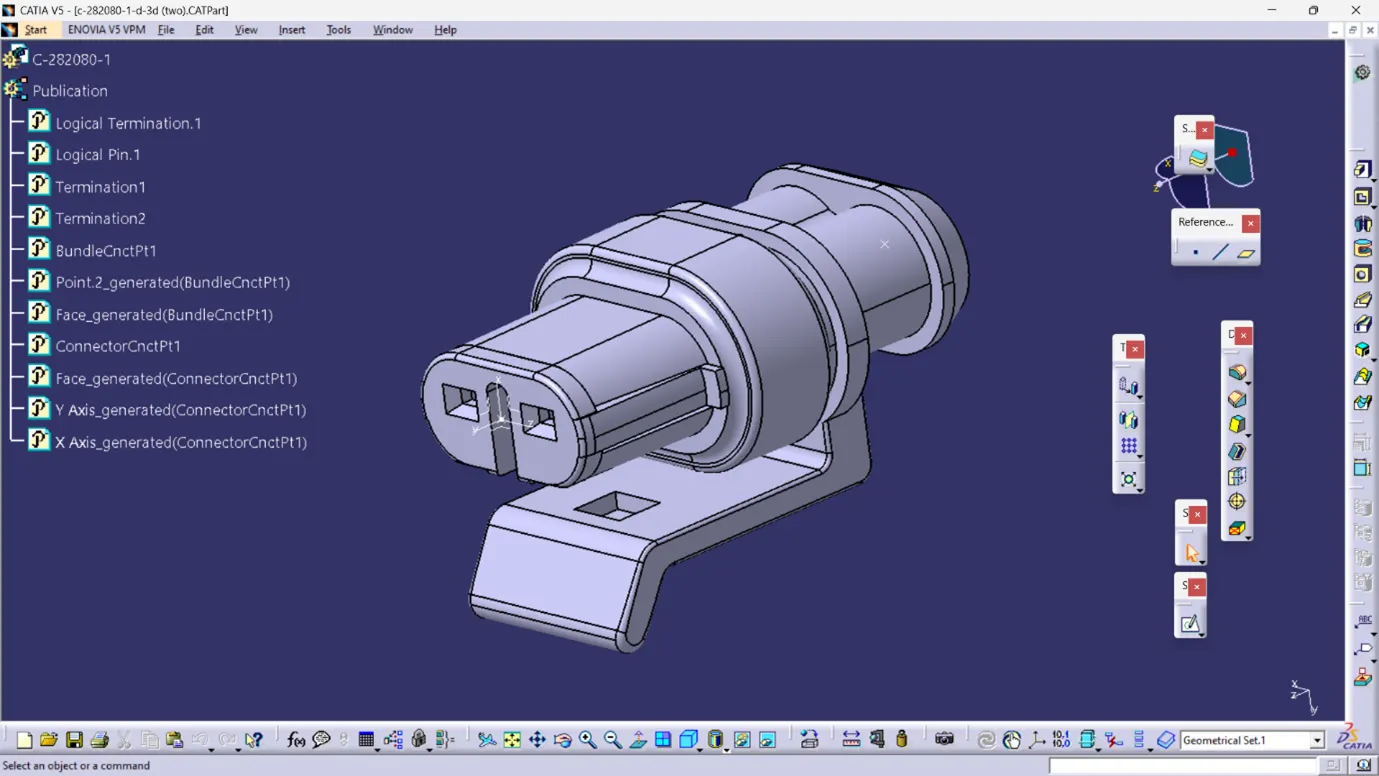
2 pole connector
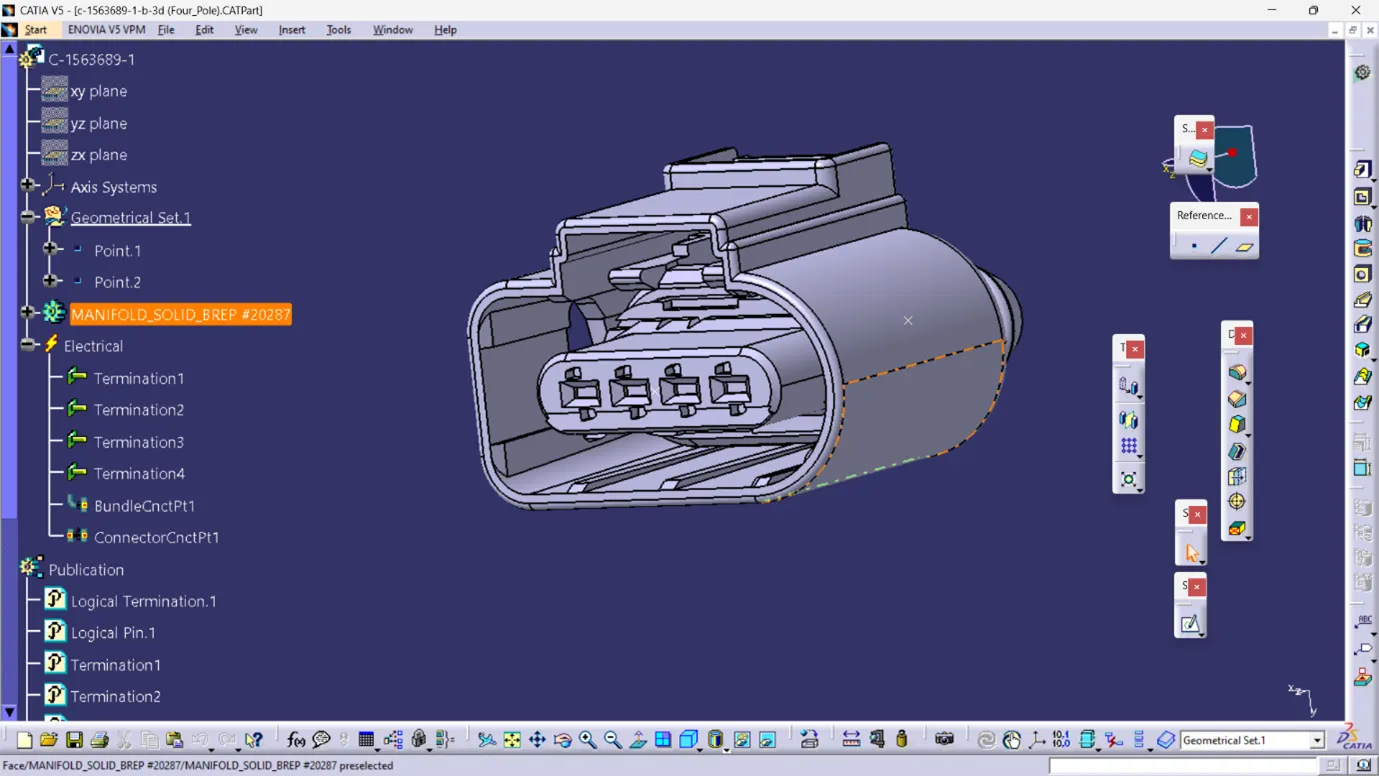
4 pole connector
STEP 3- Download and Define the plastic channel electrically
Here's a rewritten version:
1. Initiate the process of electrically defining the channel.
2. Establish bundle entry points and exit points within the channel.
3. Generate a line curve connecting the main entry and exit points to facilitate the creation of multiple branches using an external curve inside the channel.
4. Create eight bundle entry points at the openings to facilitate the connection of injector connectors.
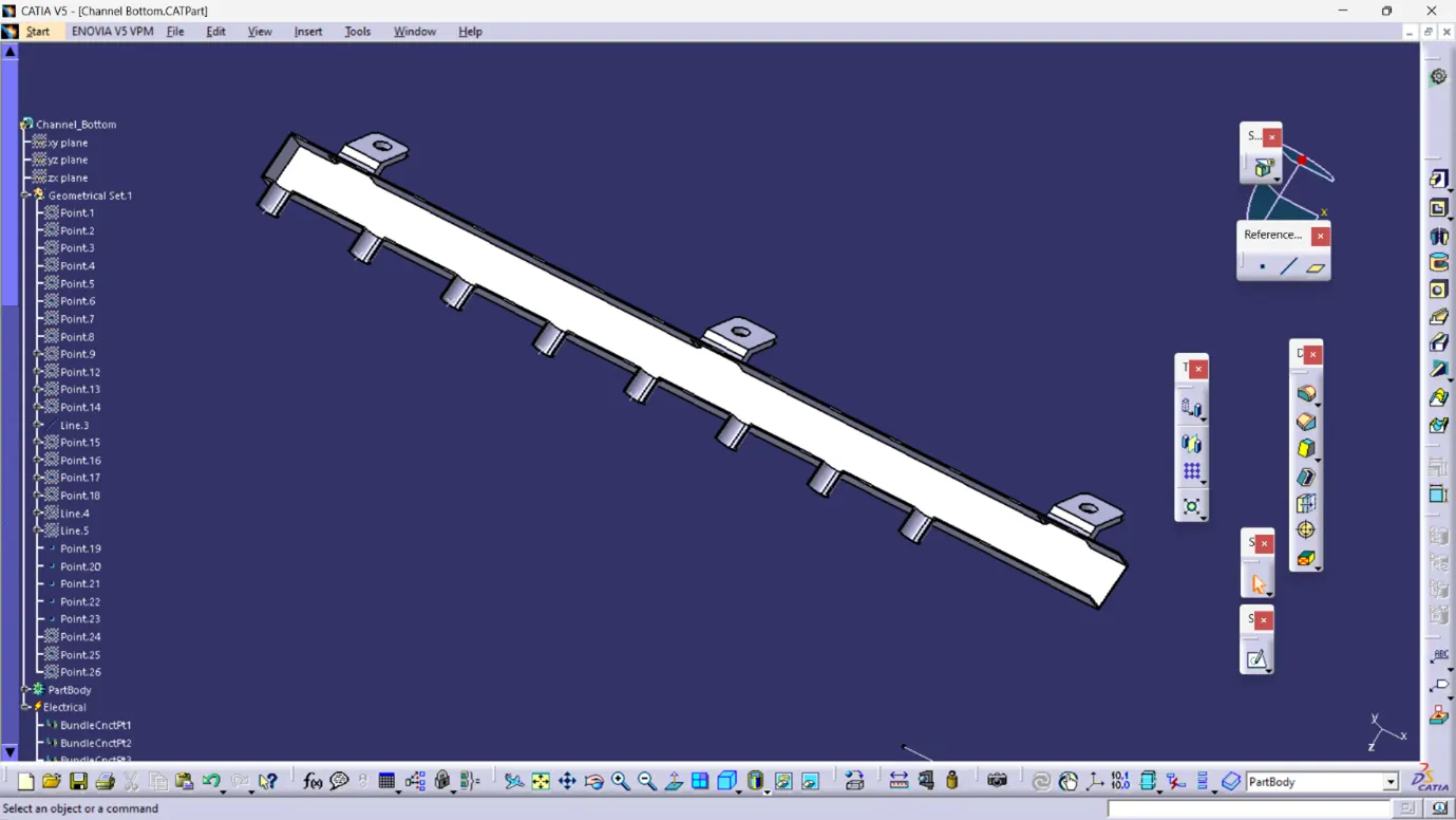
5. Utilize the established geometric parameters to define the electrical properties of the channel using the "define mounting equipment" option.
6. Define bundle entry points by employing the "define bundle connection point" option.
Then create a new product assembly with channel bottom and top part assemblyHere's a rewritten version:
1. Construct a symmetrical assembly of the channel.
2. Define the electrical properties of the bottom channel using the "define mounting equipment" option.
3. Generate all necessary geometric parameters on the symmetrical assembly. Channel Symmetrical Assembly
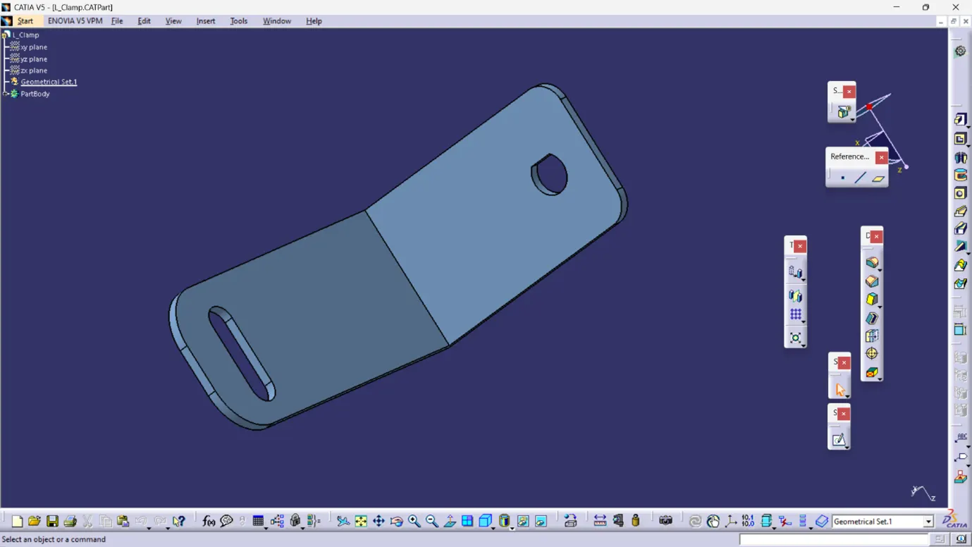
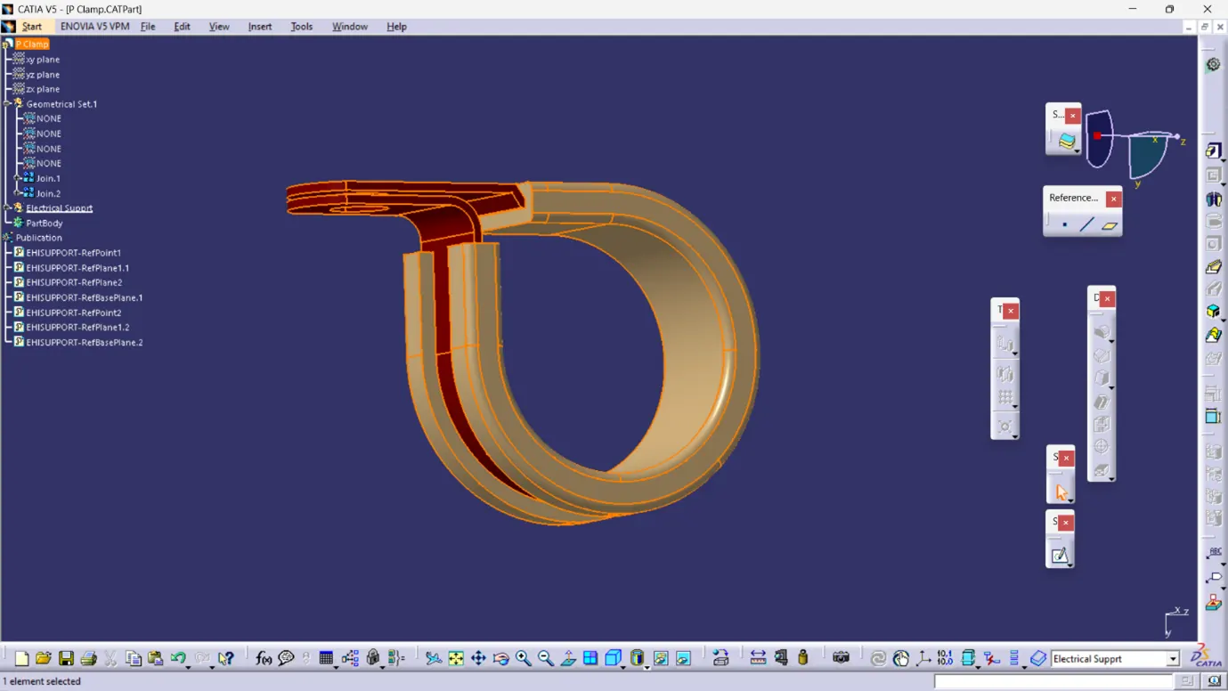
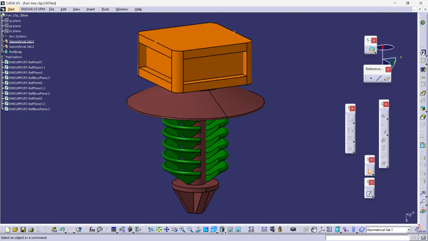
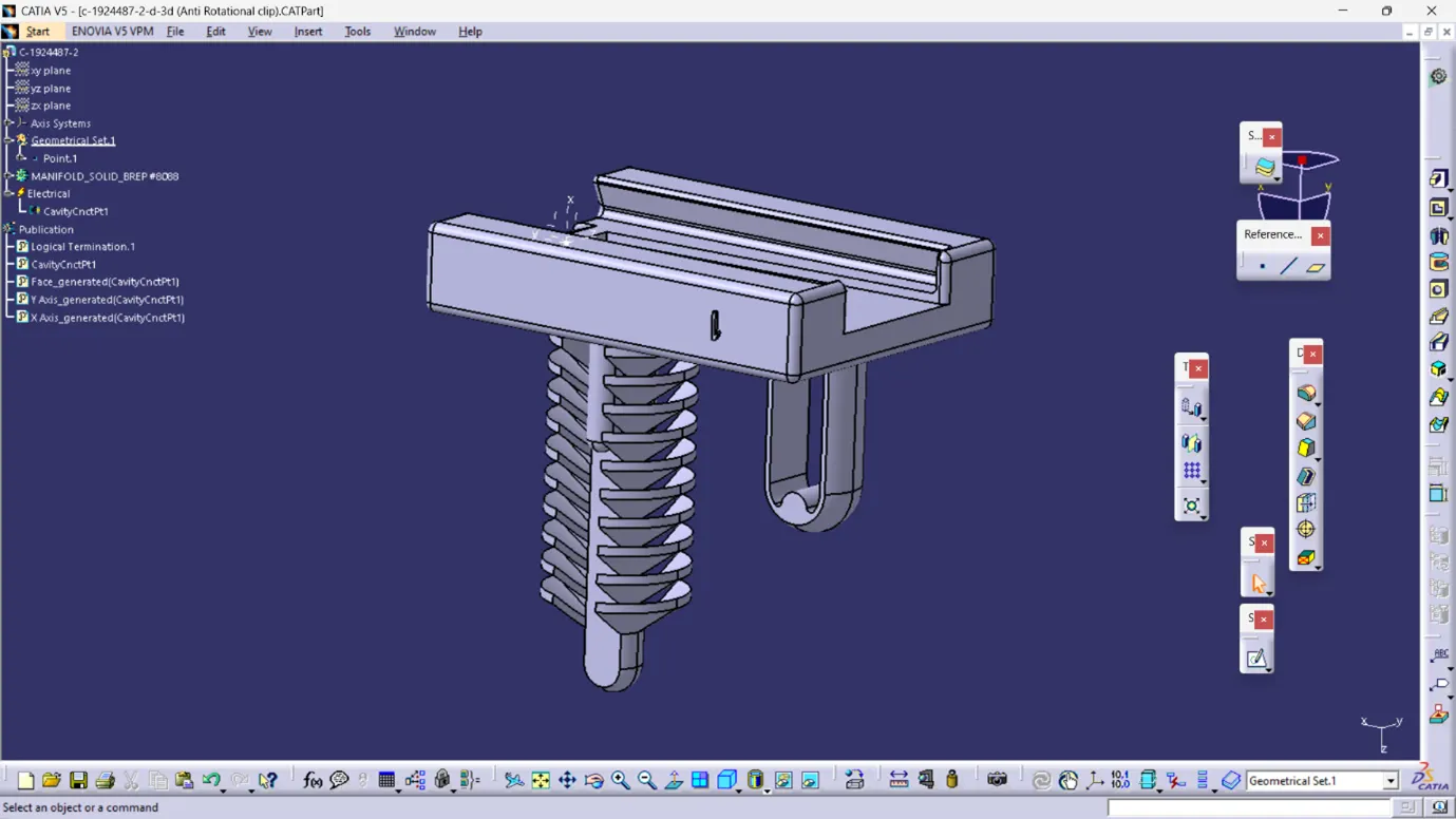
Step 4: Download and define P-clamps, L-clamps, and cavity clips.
Ensure to accurately define the properties and characteristics of each component for precise integration into the design.
Step 5: Generate a new product file for the interconnection connector and cavity assembly.
This file will serve as the foundation for integrating and assembling the connectors and cavity components within the overall system design.
Step 6: Develop the context assembly.
Context assembly is nothing but the product file which contains the engine 3D-CAD data and the engine harness geometrical bundle. Here the geometrical bundle product contains all the connectors and other mounting equipments, clips and clamps which are electrically defined for the assembly. Sheet metal L-clamp are added in the main context assembly.
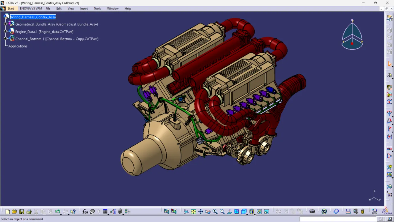
The we need to switch into the electrical harness assembly workbench and Geometrical bundle product file should be electrically defined using the Define Geometrical bundle option before adding any parts into it.
The Given V16 engine 3D-CAD model requires a total of 23 connectors to be placed on it and an inter connection connector for the engine wiring harness assy. The connectors used in this engine are as follows
8 numbers of connectors are required on the fuel injector sensors on each cylinder head, i.e.; total 16 fuel injector sensor connectors are needed.
Total 4 numbers of cam-shaft sensor connectors are needed.
1 neutral position sensor connector and 1 speed sensor connector on the gear box housing.
1 engine coolant temperature sensor placed at the center of engine
Step 7: Integrate 4-pole connectors for all fuel injector sensors and camshaft sensors.
Add 4-pole connectors to the geometrical bundle using the copy-paste connector function or by importing them directly from the previously created catalog.
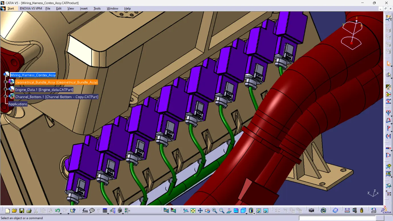
Utilize manipulation tools such as move, smart move, snap tool, and the compass to position the connectors accurately on all fuel injector sensors and camshaft sensors. Additionally, duplicate the placement of connectors by copying and pasting the initially imported connector as needed.
Step 8: Incorporate all additional connectors required for sensors such as the coolant heat sensor, neutral position sensor, and speed sensors.
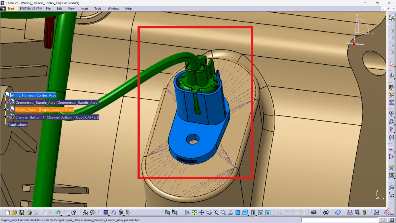
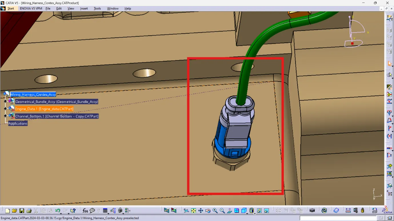
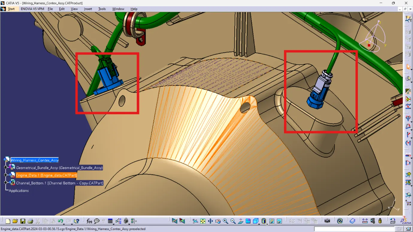
Step 9: Position the interconnection connector and L-clamp support.
Understood. In this case, it's crucial to properly secure the interconnection connectors to prevent issues such as rattling noise, physical damage, uncontrolled harness routing, and assembly errors. Here's how to address this:
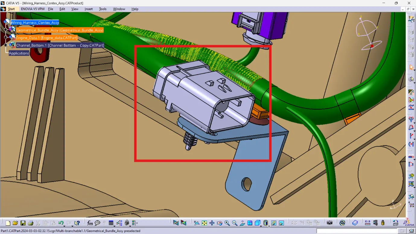
1. Secure Mounting: Utilize clips, clamps, or sheet metal brackets to securely mount the interconnection connectors within the assembly. Ensure that they are firmly anchored to prevent any movement or rattling.
2. Strategic Placement: Place the interconnection connectors in locations that comply with packaging conditions and provide optimal support. For instance, if the chassis bundle connection is coming from the right side of the engine, position the L-clamp on the right side to offer proper support for the interconnection connector.
3. Cavity Clips: Insert cavity clips into designated holes on the L-clamp to further secure the interconnection connectors in place. This helps prevent any unintended movement or dislodging.
4. Provide Slack: Allow for additional slack in the chassis bundle connecting to the engine harness interconnection connector. This extra slack helps absorb vibrations during vehicle operation, reducing the risk of damage to the wiring harness.
By following these steps, you can ensure that the interconnection connectors are properly secured and protected within the assembly, minimizing the potential for issues and ensuring reliable performance during vehicle operation.
Understood. Based on the provided information:
1. The L-Clip is mounted to one of the holes on the engine block using a screw. It is positioned in such a way that it rests on the ribs, preventing rotational movement during tightening.
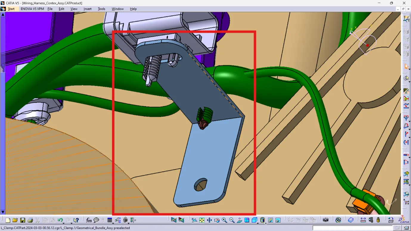
2. The interconnection connector has been placed and electrically connected, utilizing the provided cavity.
Given that the L-Clip is not part of the geometric bundle or the wire harness bundle, it should be added to the main product. This ensures proper integration and alignment within the assembly.
Step 10: Install P-clamps to ensure proper routing of the harness bundle.
By adding P-clamps at strategic locations, the harness bundle can be securely routed along the designated path, minimizing the risk of interference or damage while optimizing organization and efficiency.
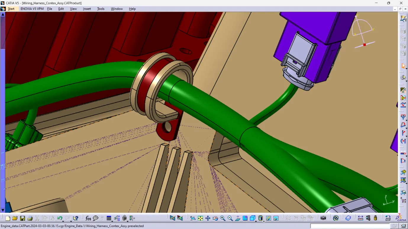
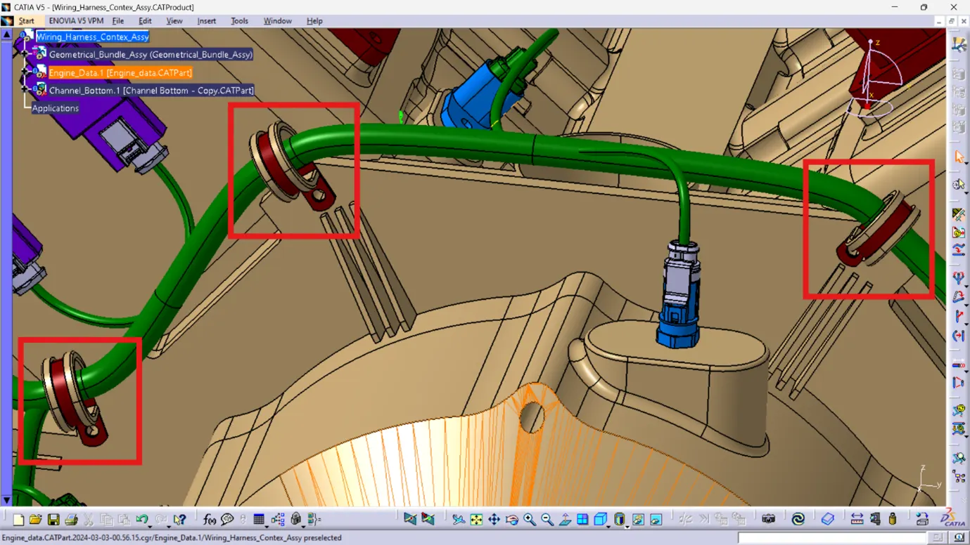
Step 11: Integrate supporting components such as P-clamps and fir tree clips to facilitate proper routing and prevent fouling of the harness bundle by unwanted mechanical components.
1. Place P-clamps at necessary locations to ensure optimal routing for the harness bundles. Mount them to the holes provided on the engine block, utilizing screws for secure attachment.
2. Position fir tree clips according to the specific requirements during wire harness routing. Once the routing is finalized, coordinate with the engine design team to request the addition of holes for the fir tree clips as per their designated locations.
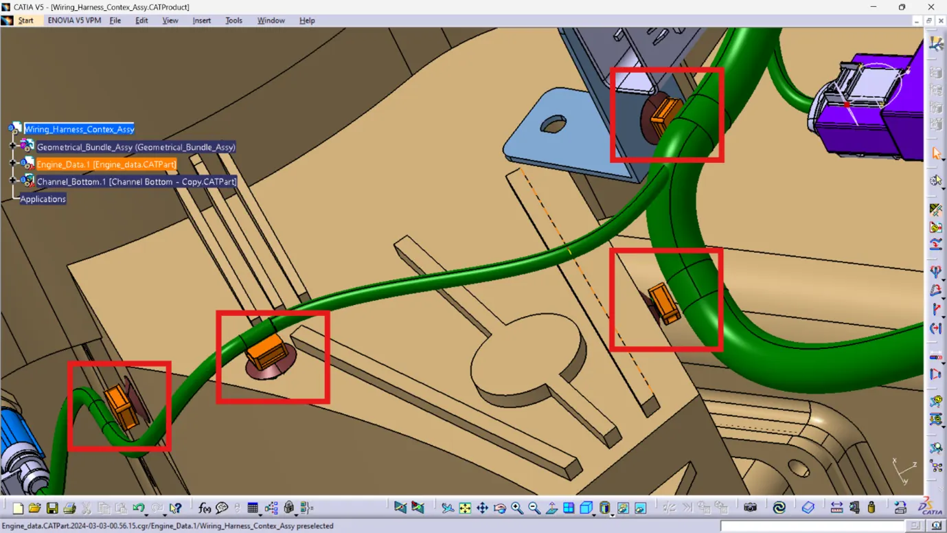
By incorporating P-clamps and fir tree clips strategically, the harness bundle can be efficiently routed while minimizing the risk of interference or damage from surrounding mechanical components.
Step 11: Position channels at the designated locations.
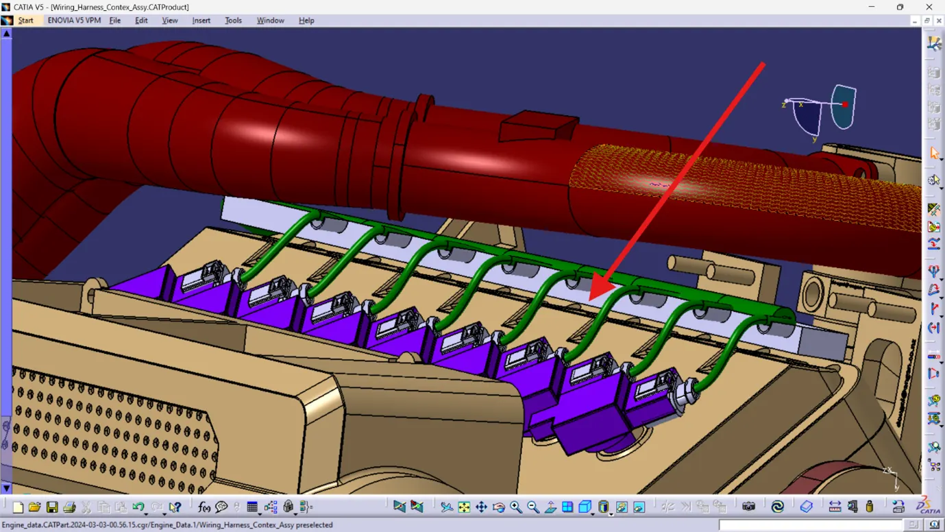
Utilize plastic guiding channels to meet clearances in critical areas where achieving proper routing with clamps is challenging.
Plastic guiding channels provide additional support and ensure proper clearance for the wiring harness bundle, especially in areas where space constraints make the use of traditional clamps impractical or difficult.
Consideration of packaging rules and best practices is crucial during wire harness routing and placement of clips and clamps. Here are some important guidelines:
1. Maintain a minimum distance of 200mm between two clamps on a straight branch.
2. Ensure the minimum branch length is 50mm.
3. Maintain a minimum distance of 25mm between a clip and the nearest branching point.
4. Keep a minimum distance of 200mm between two straight connection points.
5. Ensure a minimum distance of 50mm between two breakout points.
6. Limit the number of branches from a single branch point to 4.
7. Avoid routing the wiring harness near exhaust manifold and other unshielded heat sources; if unavoidable, maintain a minimum distance of 200mm.
8. Utilize available threaded bosses on the engine or minimize the use of metal brackets.
9. Provide sufficient clamps to ensure clearance and safety of the wiring harness.
10. Incorporate P-clamps, fir tree clips, and other clips into the geometric bundle, as they are electrically defined and part of wire harness routing.
11. Allow enough slack in the wiring harness to prevent damage during engine rocking or starting.
12. Ensure wire routing facilitates ease of manufacturing and serviceability while considering cost-effectiveness.
13. Avoid routing and clipping in blind zones of operators during assembly and service.
14. Provide proper slack at end connectors to avoid tension on the wire bundle.
15. Avoid sharp edges on sheet metal parts; if unavoidable, provide protective parts to prevent wire bundle damage.
16. Provide separate branch points for individual connectors to ensure Poka-Yoke (error prevention).
Adhering to these packaging rules, initiate the wire harness routing process while considering the components present in the engine assembly.
Step 12: Initiate the wiring harness routing process.
Utilize the established packaging rules and best practices to systematically route the wiring harness, ensuring optimal placement and adherence to safety and performance standards.
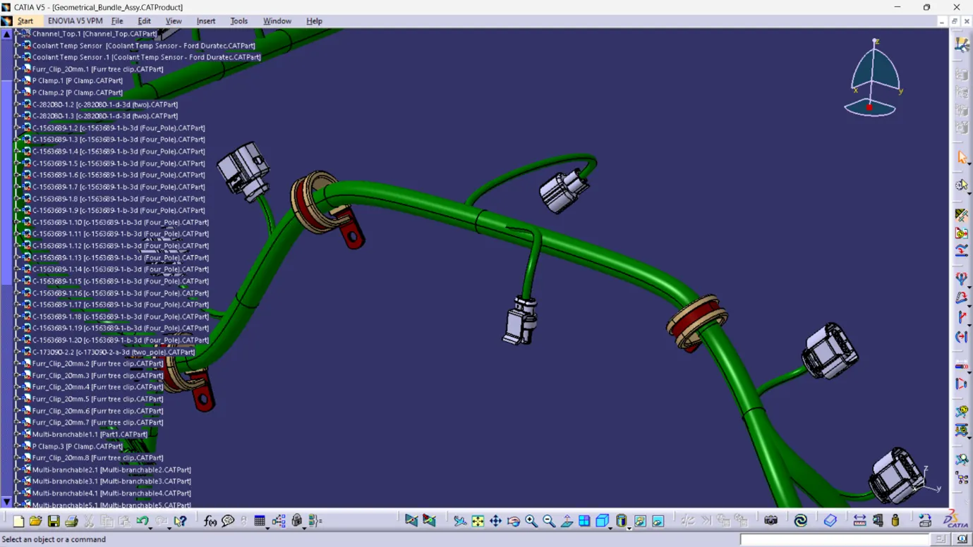
Harness Routing Procedure for the Channel:
1. Create a multi-branchable bundle using the external curve option and select the previously created line.
2. Once the bundle segment is created, establish 8 branch points inside the channel to create sub-branches for the injector sensor connectors.
Add branch points at a minimum distance of 25mm from clips and clamps to create new sub-branches connecting various connectors.
After completing the routing process, it's essential to check for any interaction between the wire bundle and the engine part.
Ensure there is proper clearance between the wire bundle and the engine components to prevent any interference or damage.
If necessary, add additional slack or fir tree clips to ensure proper routing and clearance.
Complete the assembly of the final wire harness for the engine.
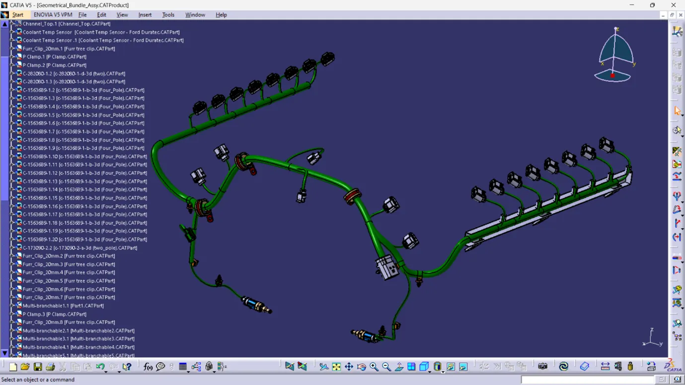
Step 13: Conduct an electrical continuity check.
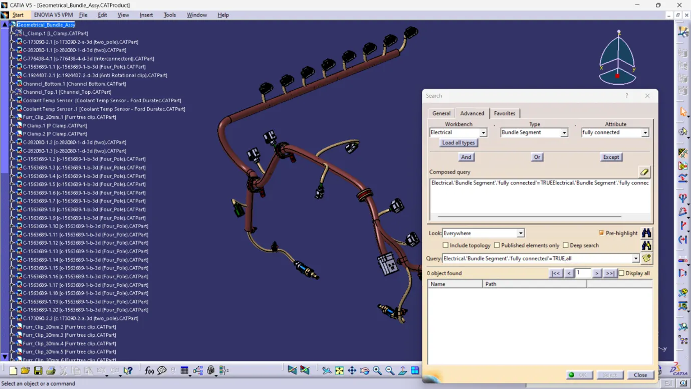
1. Navigate to "Edit" and click on the "Search" command.
2. Go to "Advanced" settings.
3. Choose the workbench as "Electrical," type as "Bundle Segment," and attribute as "Fully connected."
4. The search result should display either "TRUE" or "FALSE" to indicate the connectivity analysis result.
This process ensures that the entire wire bundle is fully connected, confirming proper electrical continuity within the system.
Results:
Selecting the "TRUE" option will display all the connected bundle segments, while selecting "FALSE" will show all the non-connected bundle segments.
In this case, selecting "TRUE" and searching for results reveals that all the bundle segments are highlighted and found, indicating that all the bundle segments are electrically connected.
Step 14: After completing the wire harness routing in accordance with the packaging rules, provide protection parts where necessary.
To protect the wiring harness in high-temperature zones, several methods can be employed, including:
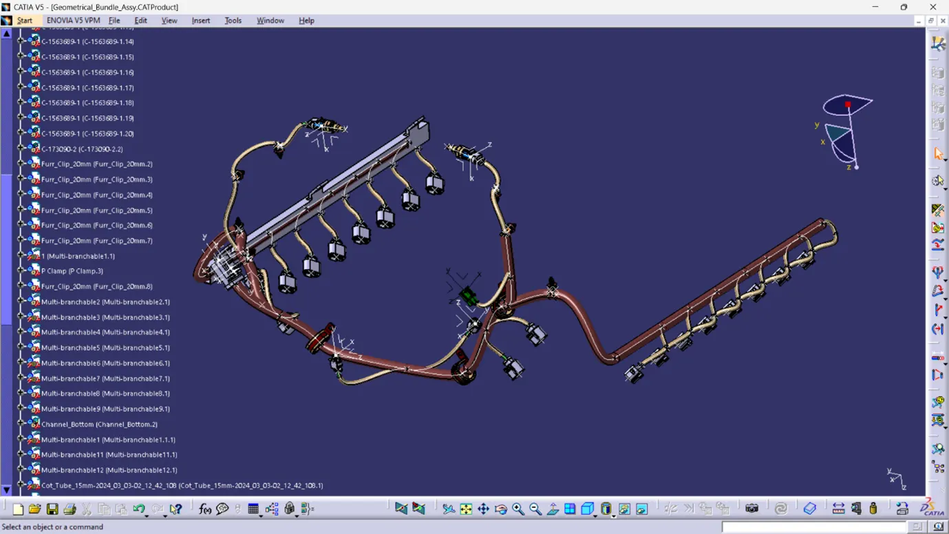
1. Use of Corrugated Tubes:
- Corrugated tubes, also known as COT tubes or convoluted conduits, are flexible and made from plastic.
- There are two types: slit and non-slit.
- Slit COT tubes are particularly useful for easily inserting and securing wires within the tube.
- These tubes provide insulation and protection against heat, abrasion, and other environmental factors, making them ideal for automotive applications.
2. Application of Slit-COT Tubes and Cotton Tapes:
- Slit-COT tubes can be added to the wiring harness bundle to provide additional protection.
- Cotton tapes can also be used for bundling and securing wires, offering insulation and abrasion resistance.
- These materials help safeguard the wiring harness against heat and mechanical damage.
3. Incorporation of Plastic Guiding Channels:
- The top part of plastic guiding channels can be added to further protect the wiring harness.
- These channels provide structural support and help maintain proper routing, ensuring the wires are safely organized and insulated.
By employing these protection methods, the wiring harness can withstand high temperatures and harsh conditions, ensuring reliable performance and longevity in automotive applications.
Plastic materials used in wiring harness protection and their temperature resistance are as follows:
- Polypropylene (PP): Suitable for temperatures ranging from -20 to 100 degrees Celsius.
- Heat Resistant (HR): Designed for temperatures from -20 to 135 degrees Celsius.
- Flame Retardant (FR): Specifically formulated for temperatures between -20 to 135 degrees Celsius and possesses flame retardant properties.
- Polyamide/Nylon (PA): Offers a wider temperature range, effective from -20 to 180 degrees Celsius.
These materials are selected based on their temperature resistance properties, ensuring optimal performance and protection of the wiring harness in various operating conditions.
In scenarios where corrugated tubes are unsuitable for very high temperature zones, such as in exhaust areas, the use of braided tubes (Nylon woven loom) and silica sleeves can be considered.
1. Braided Tubes (Nylon Woven Loom):
- Braided tubes are expandable sleeves braided from flame-resistant polyphenylene sulfide (PPS) monofilament fiber.
- They are extremely lightweight, resistant to high temperatures (up to 285 degrees Celsius), and virtually impervious to solvents.
- Braided tubes provide excellent protection against heat and abrasion, making them suitable for use in demanding environments like exhaust areas.
2. Silica Sleeves:
- Silica sleeves are heat-resistant sleeves made from silica fibers.
- They offer excellent thermal insulation and protection against high temperatures.
- Silica sleeves are lightweight, flexible, and resistant to abrasion and chemicals.
- They are commonly used to shield wiring harnesses and components from extreme heat, such as in engine compartments and exhaust systems.
By utilizing braided tubes and silica sleeves in high-temperature zones, the wiring harnesses are effectively protected from heat-related damage, ensuring reliable performance and longevity in demanding operating conditions.
When applying protection parts to the required harness bundles, the selection of corrugated tubes is primarily determined by the diameter of the wiring harness bundle and temperature resistance requirements.
Diameter Compatibility: Choose corrugated tubes with a diameter that matches the size of the wiring harness bundle to ensure a snug fit and effective protection.
Temperature Resistance: Consider the operating temperature of the environment where the wiring harness will be installed. Select corrugated tubes with temperature resistance properties that meet or exceed the requirements of the application.
Color Selection: While black corrugated tubes are commonly used in automotive and off-road applications due to their versatility and durability, other colors may be employed to highlight critical harnesses. For instance, emission system harnesses may be designated with specific colors to aid identification and maintenance.
By carefully selecting corrugated tubes based on diameter, temperature resistance, and color requirements, the wiring harnesses can be effectively protected and visually distinguished for enhanced maintenance and troubleshooting.
Final Product
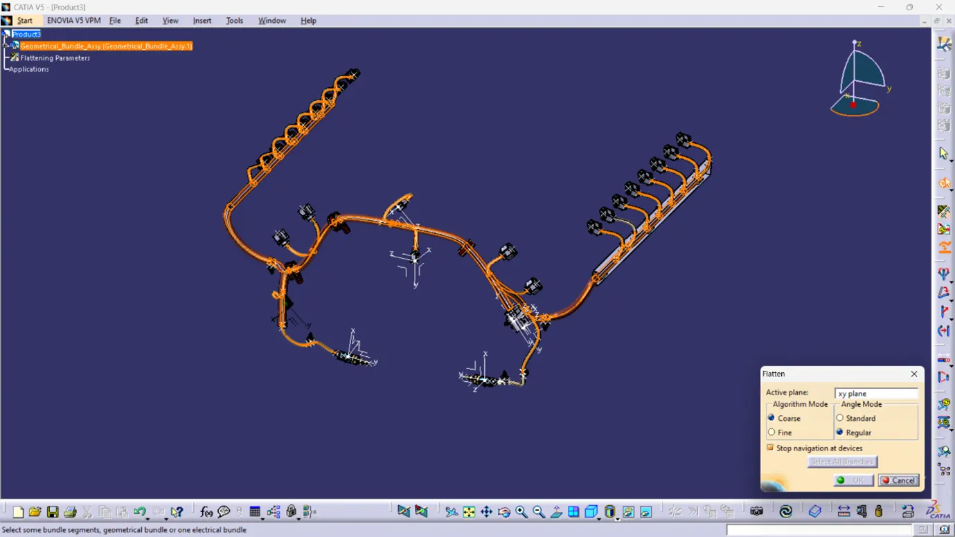
Step 15: Wiring Harness Flattening
To flatten the wiring harness bundle, follow these steps:
1. Create a new product file and switch to the electrical harness flattening workbench.
2. Define the harness flattening parameters.
3. Extract the geometric bundle from the wiring harness context product file.
4. Select all the branches and flatten the entire geometric bundle.
5. The bundles can be rotated and rolled with a proper radius to ensure they fit the drawing sheet accurately.
6. Final Flattened Engine Geometrical Bundle: Ready for Drawing Integration
Step 16: Flattened Harness View in the Drawing Sheet
1. Ensure that in the flatten parameter settings, bundles and protective coverings have different graphical representations:
- Bundle Segments: Single line representation
- Protective Coverings: Double line representation
2. Create a new drawing file in the drafting workbench.
Insert the flattened harness product into the drawing sheet by following these steps:
1. Access the view option in the drafting workbench.
2. Select the front view command.
3. Insert the flattened harness product into the drawing sheet.
Customize the drawing sheet view according to the required parameters by adjusting settings such as scale, dimensions, annotations, and title block information.
Title: Engine Wiring Harness Flattening Drawing
Conclusion:
Throughout this project, the routing of the wiring harness for the V16 Engine assembly was completed meticulously, adhering to various packaging rules and constraints. The flatten-view drawing was successfully prepared in CATIA V5, ensuring accurate representation of the wiring harness layout. Additionally, considerations were made for future modifications, such as requesting the Engine design team to provide additional holes for the mounting of Fir tree clips. This project demonstrates effective collaboration between design and engineering teams to achieve optimal wiring harness routing and integration within the overall engine assembly.
https://drive.google.com/file/d/1QHfbwoX9MuSUPEy97NzFLpcqey5t-Qh8/view?usp=sharing
The file size is bigger then required size that's why i have attached g drive link here