Project 1
Report on Designing a Mold for a Table Fan Base in SolidWorks
1. Introduction
The objective of this report is to document the process of designing a mold for a table fan base using SolidWorks. The design includes considerations for manufacturability, accuracy, and ease of use.
2. Initial Setup
- Software Preparation: Ensure that SolidWorks is properly installed and configured.
- Model Import: Import the provided table fan base model into SolidWorks.
3. Analyzing the Model
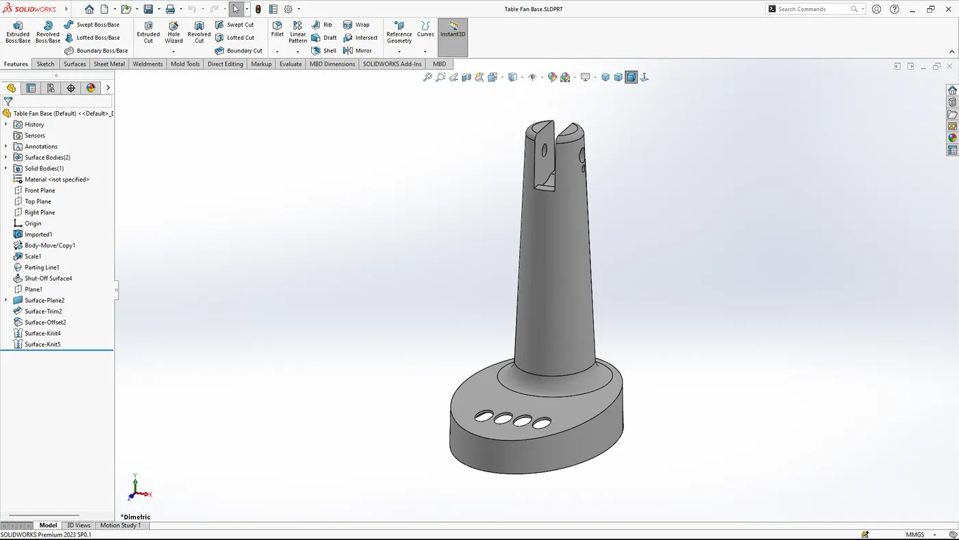
- Inspect Geometry: Carefully examine the geometry of the table fan base to identify critical features and potential issues.
- Determine Parting Line: Decide on the most suitable parting line for the mold. This is crucial for ensuring proper mold release and minimizing defects.
4. Creating the Mold
- Scaling the model:
- Scale the model according to the shrinkage value of the plastic material.
- In this case it is given the material type is "ABS".
- The shrinkage value for this is 0.6%.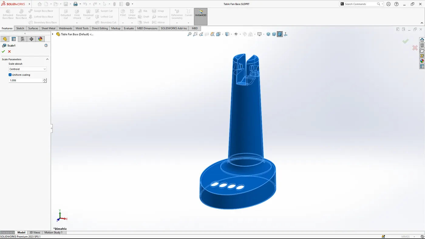
- Define the Parting Line:
- Open the part file in SolidWorks.
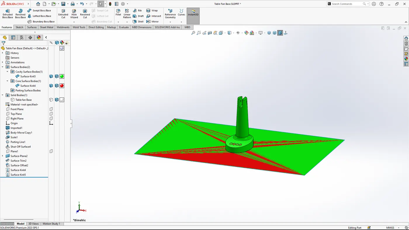
- Use the `Draft Analysis` tool to determine draft angles and find the optimal parting line.
- Create the parting line by selecting `Insert > Mold Tools > Parting Line`.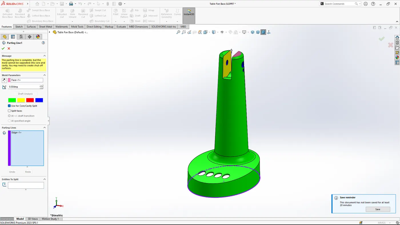
- Defining the Shut-off surface:
- Define the shut-off surface for the openings.
- In this case the shut-off surface is shown below image.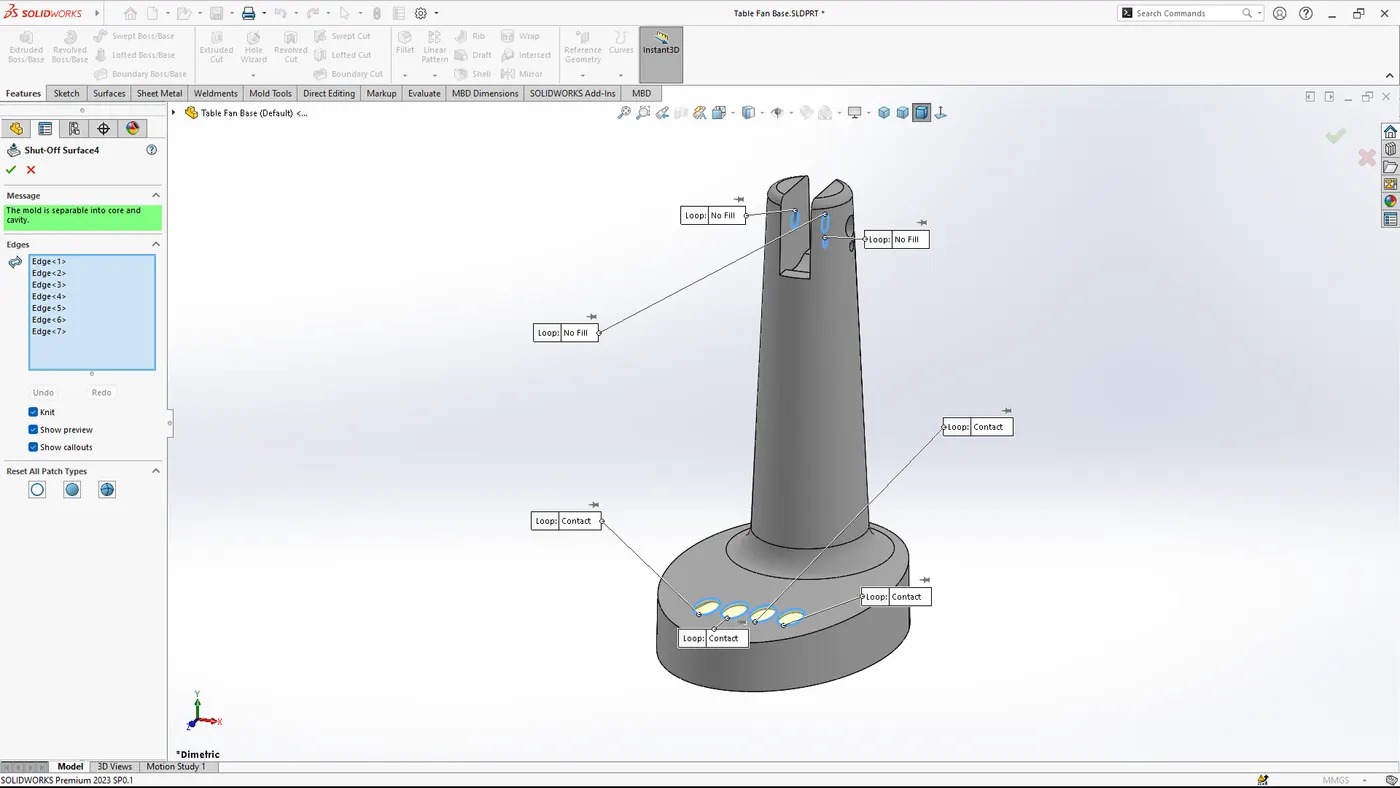
- Create the Parting Surfaces:
- Generate parting surfaces using `Insert > Mold Tools > Parting Surfaces`.
- Ensure the surfaces completely enclose the parting line.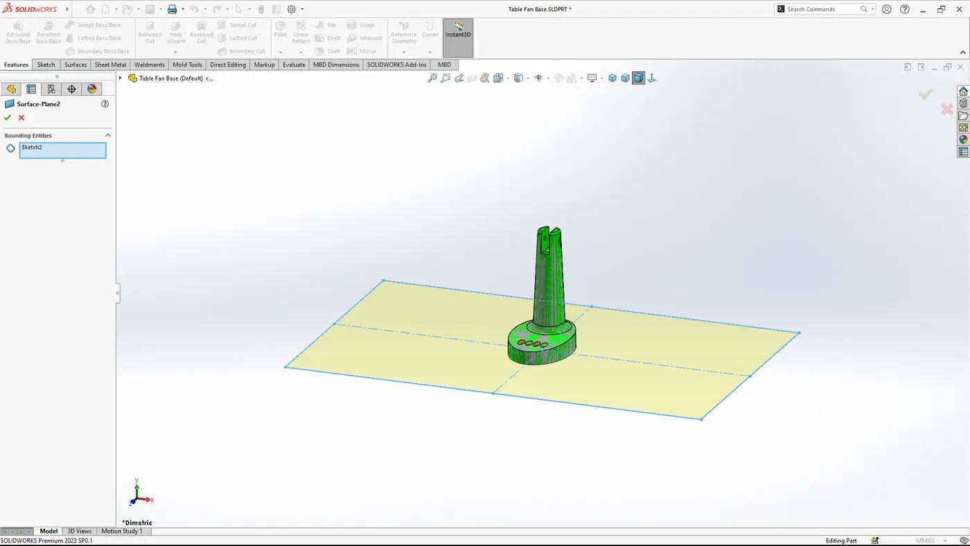
- Core and Cavity Creation:
- Use the `Tooling Split` command to separate the model into core and cavity.
- Access this via `Insert > Mold Tools > Tooling Split`.
- Define the direction of pull and confirm the core and cavity are properly divided.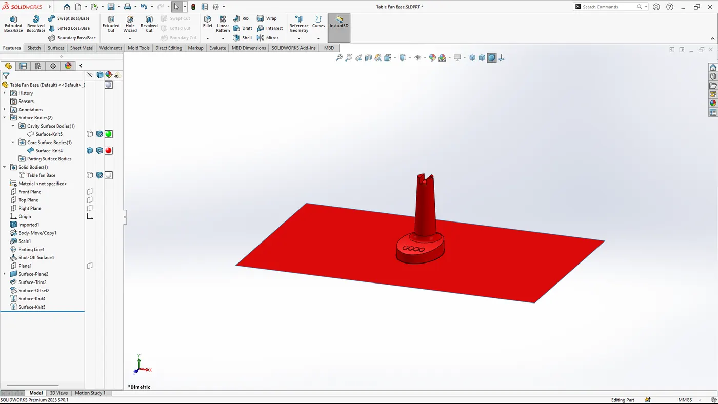

- Generate the Mold Base:
- Choose an appropriate mold base from the SolidWorks Mold Base Library.
- Customize the mold base dimensions to fit the table fan base model.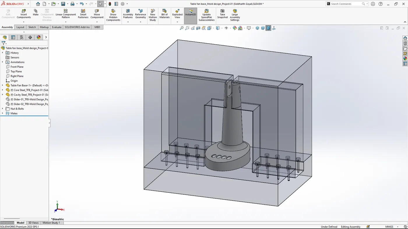
5. Finalizing the Mold Design
- Add Sliders:
- Add the sliders where undercuts are present.
- Create the sketch where the slider needed to be placed.
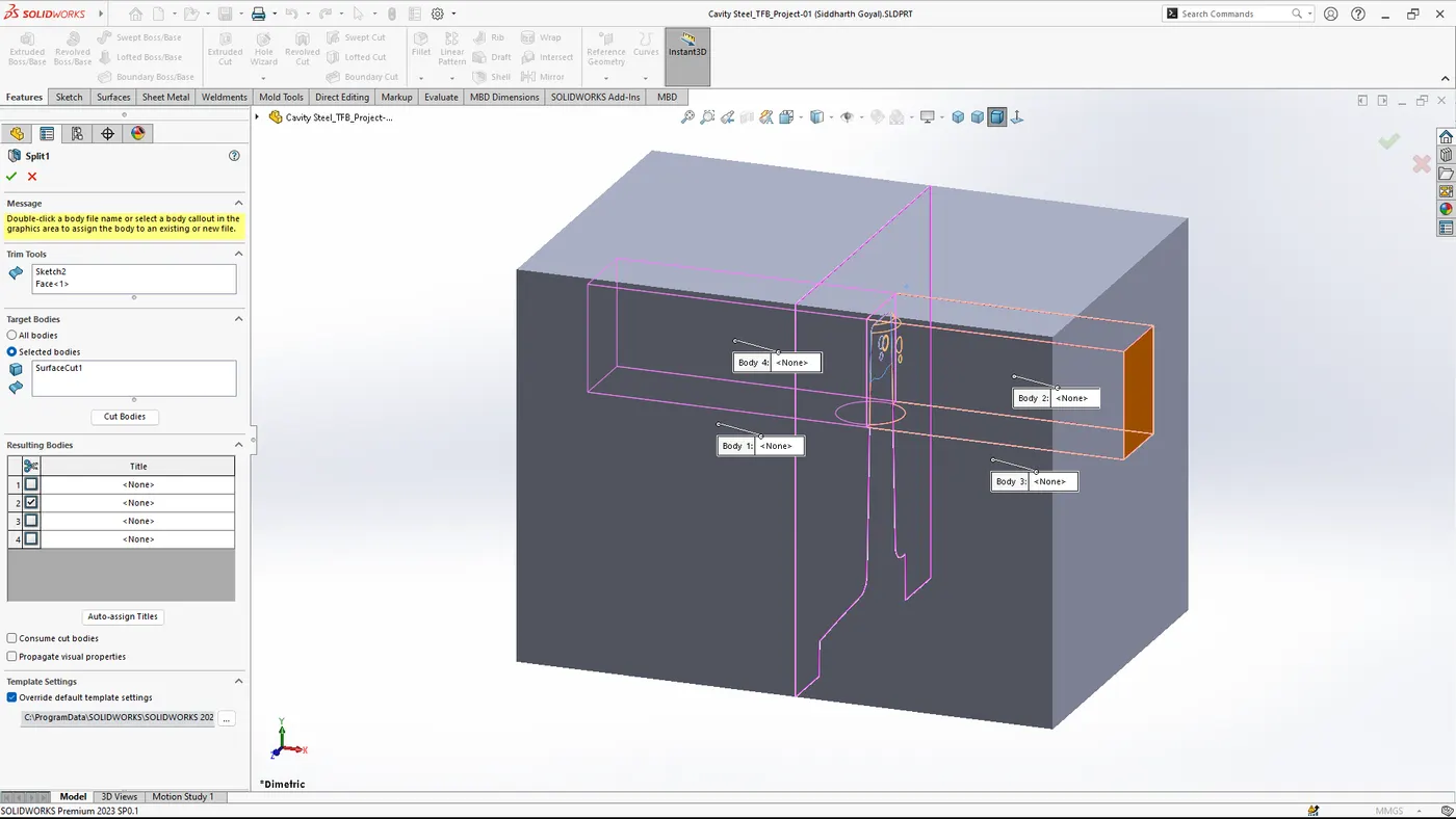
- Split the part from the mold.
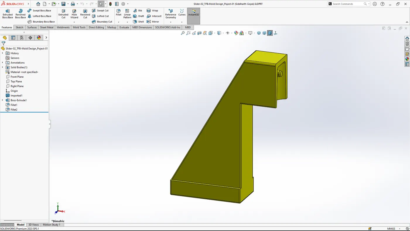
- Save the slider separately (as a new file).
- Repeat the same process for other undercuts, wherever needed.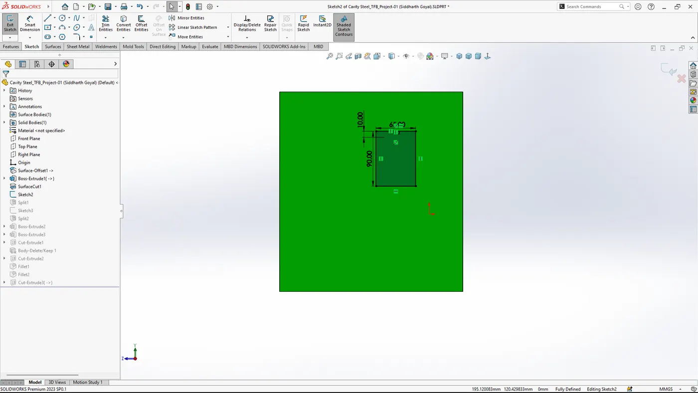
- Add Ejector Pins:
- Insert ejector pins where necessary to ensure the part can be ejected from the mold without damage.
- Use `Insert > Mold Tools > Ejector Pin`. - Cooling Channels:
- Design cooling channels to ensure the mold can be cooled effectively during the injection process.
- Access this via `Insert > Mold Tools > Cooling Channel`. - Create Runner System:
- Design the runner system to allow molten material to flow into the mold cavity.
- Utilize `Insert > Mold Tools > Runner`.
6. Simulation and Validation
- Mold Flow Simulation:
- Run a mold flow simulation to identify potential issues with the injection process.
- Use `SolidWorks Plastics` to perform the simulation. - Validate Draft Angles:
- Ensure all surfaces have appropriate draft angles to facilitate mold release.
7. Conclusion
This report details the step-by-step process of designing a mold for a table fan base in SolidWorks. By following these steps, a functional and manufacturable mold can be created, ensuring efficient production and high-quality parts.