Project 1
CAR SIDE DOOR WIRING HARNESS DESIGN - PROJECT 1
AIM
To route the Wiring harness on given car body front door and prepare flatten view drawing in CATIA V5.
INTRODUCTION
A wire harness, also commonly referred to as a wiring harness, is an exterior sheath used to cover some types of electronic wires. Generally, wiring harnesses are made of thermoplastic or thermoset materials that can help protect the cables from the environment.
Automobiles today come with some great features. Their design, though, calls for deft wiring considerations. An automotive wiring harness is an assembly of wires, connectors, and other electrical parts. You use it in a vehicle for the transmission of signals.
OBJECTIVE
- Define all the mechanical connectors electrically and save it in the Catalogue.
- Place required Connecters on the Back door CAD data.
- Place Fir Tree clips at the required position by following the packaging rules.
- Create the Wiring Harness Routing with all the electrically defined connectors and mounting equipments.
- Create branching points at required locations to create sub branches and connect to various connectors in the geometrical bundle.
- Apply Protection coverings as required.
- Create Wiring harness flattening for the final geometrical bundle.
- Using the drafting workbench, create a drawing sheet with the flattened wiring harness.
DESIGN METHODOLOGY
Some important packaging rules and best practices to be considered during wire harness routing and placing of the clips and clamps are as follows –
- Distance between two clamps on a straight branch should be maximum of 200mm.
- The minimum branch length should be 50mm.
- Minimum distance between clip and nearest branching point should be 25mm.
- The minimum distance between two straight connection points should be 200mm.
- The minimum distance between two breakout points should be 50mm.
- To limit the number of branches from a single branch point to 4.
- Enough clips clamps shall be provided to ensure positive clearance with surroundings and safety of wiring harness.
- Fir tree clips and other clips can be added to the Geometric bundle as they are electrically defined and are part of the Wire harness routing and should be provided with the Wire bundle package.
- Enough slack should be provided to the wiring harness which help not to get damaged during the opening and closing of Back Door.
- Easy manufacturing, installation, removal and maintenance have to be considered while designing the wire harness.
- The wire routing should be done keeping in mind the cost effectiveness of the bundle package.
- To avoid the harness routing and clipping in blind zones of the operator during the assembly and the service.
- To provide proper slack at end connectors so that there will be no tension on the wire bundle.
- To avoid sharp edges on the sheet metal parts and if it is not possible then provide protection parts to prevent damage of the wire bundle.
- Routing through small structural holes and openings shall be avoided. To minimize chaffing and handling of the wiring harness during installation.
- To provide separate branch points for separate connectors to ensure Poka-Yoke.
- The bend ratio for all the bundle segment is considered to be 1.4
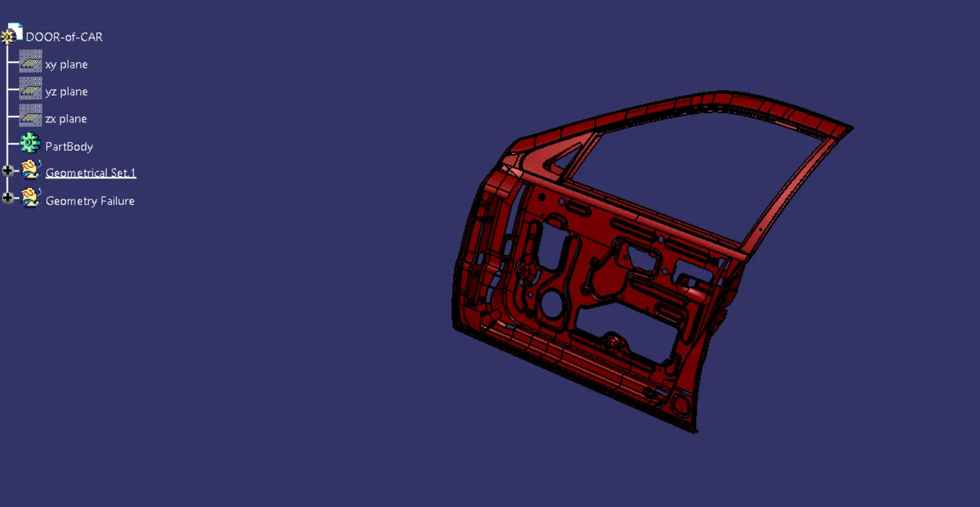
Step 1- download the front Door CAD data from the given source.
Step 2 – Creating the context assembly
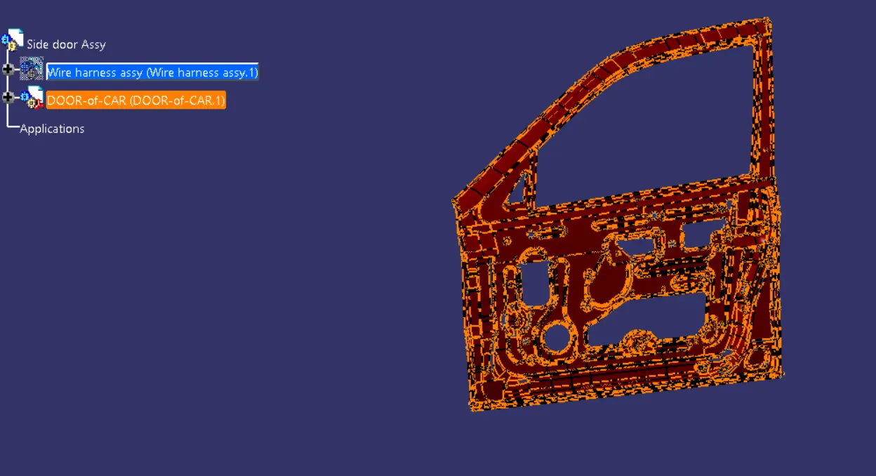
- Context assembly is nothing but the product file which contains the back door 3D-CAD data and the back door geometrical bundle. Here the geometrical bundle product contains all the connectors and clips which are electrically defined for the assembly.
- Create new product file and rename it as Back door harness assembly context.
- Now add the back door CAD data into the context assembly and also creating the geometrical bundle product file inside the context assembly.
- Define the geometrical bundle product file electrically using the geometrical bundle command.
Step 3 – Add required suitable Connectors from the Connectors Catalogue.
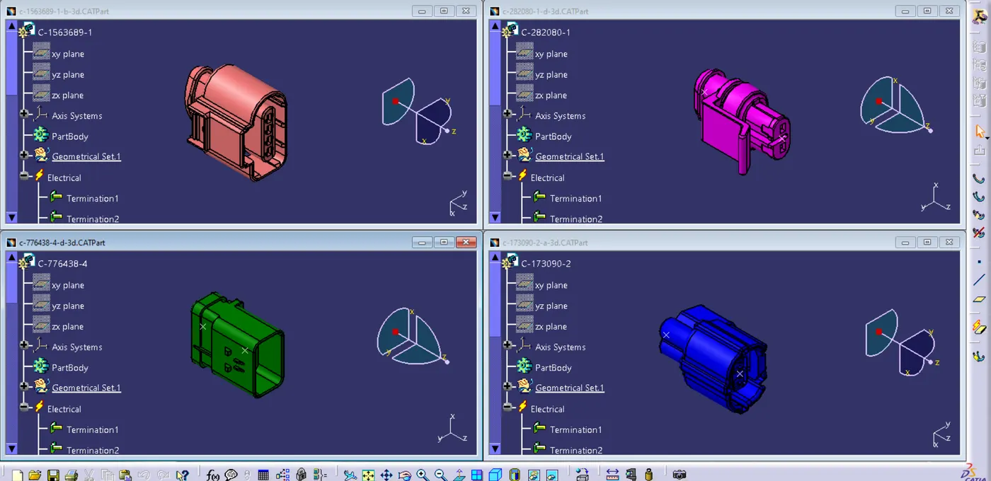
Back Door Harness Assembly requires the following connection connectors
- Inter connection Connector – 1
- Top mounted stop light connector – 1
- Defogger connectors – 2
- Brake Light Assembly Connections – 2(LH and RH)
- Number plate Light Connections – 2
- Wiper motor Connection - 1
Connectors selected for the cack door harness assembly are as follows
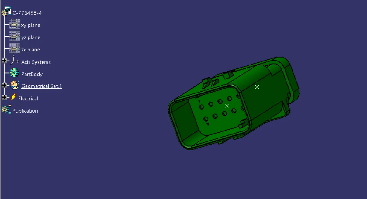
Interconnection Connector C-776438-4
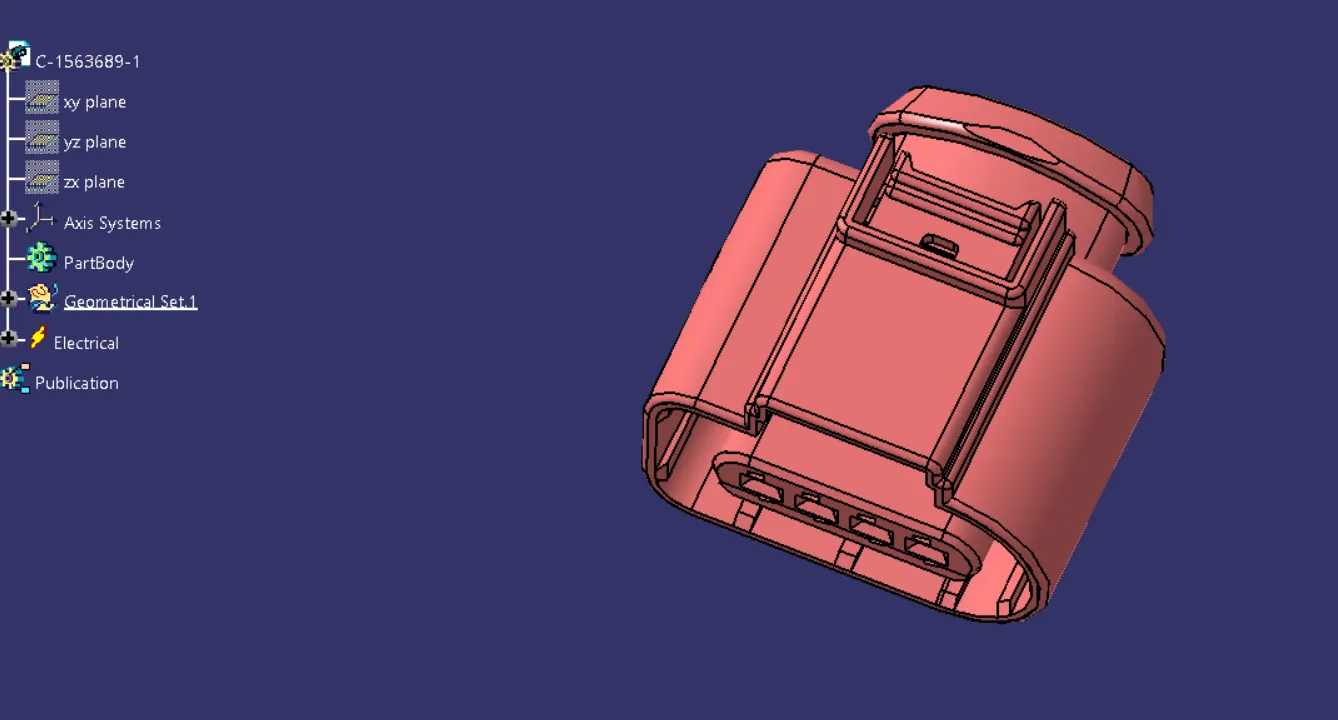
C-1563689-1 used for Brake Light assembly connections and Wiper motor connection
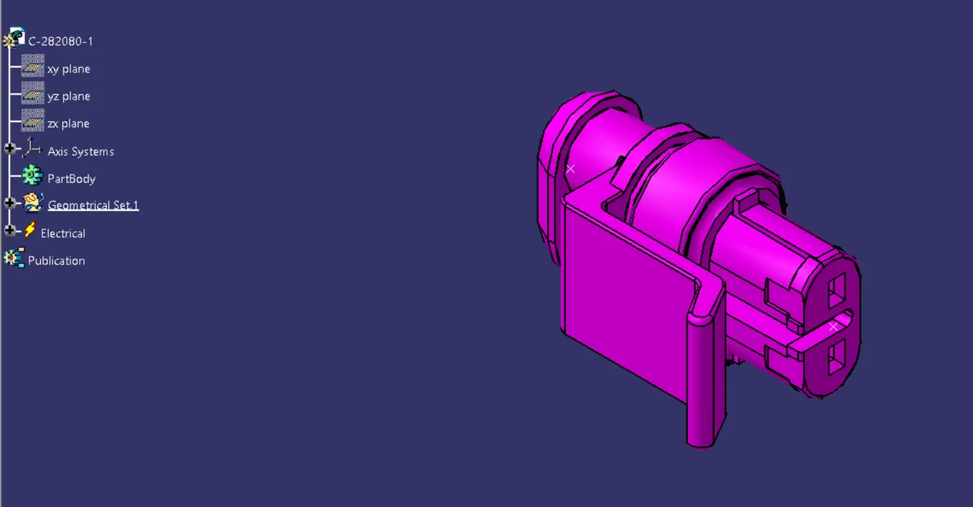
C-282080-1 used for defogger and numberplate connections
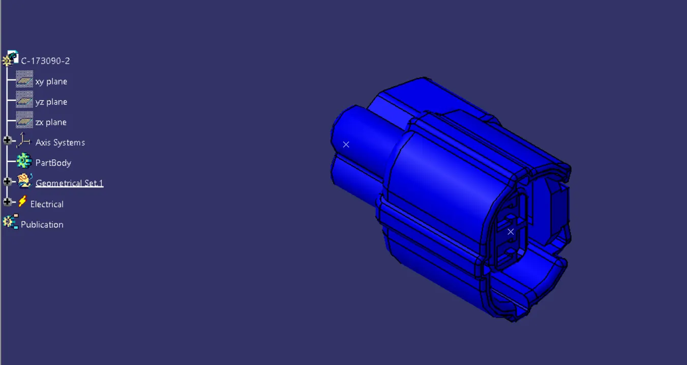
C-173090-1 for high Mount stop Light
Step 4 – Placing fir tree clips to the required locations to ensure proper harness routing throughout the Assembly.
- Ensure no fouling of harness to the back door sheet metal components.
- Enough clamps shall be provided to ensure the positive clearance with surrounding and safety of wiring harness. Distance between two clamps/clips on a straight branch should be maximum of 200mm. However clamping requirements should be decided based on the harness bending and mounting arrangements.
- Distance measurements between clips provided in the assembly
Step 5 - Wiring Harness Routing
- Add branch points at minimum of 25mm distance from clips and clamps to create new sub branches connecting various connectors.
- Minimum length of bundle should be 50mm.
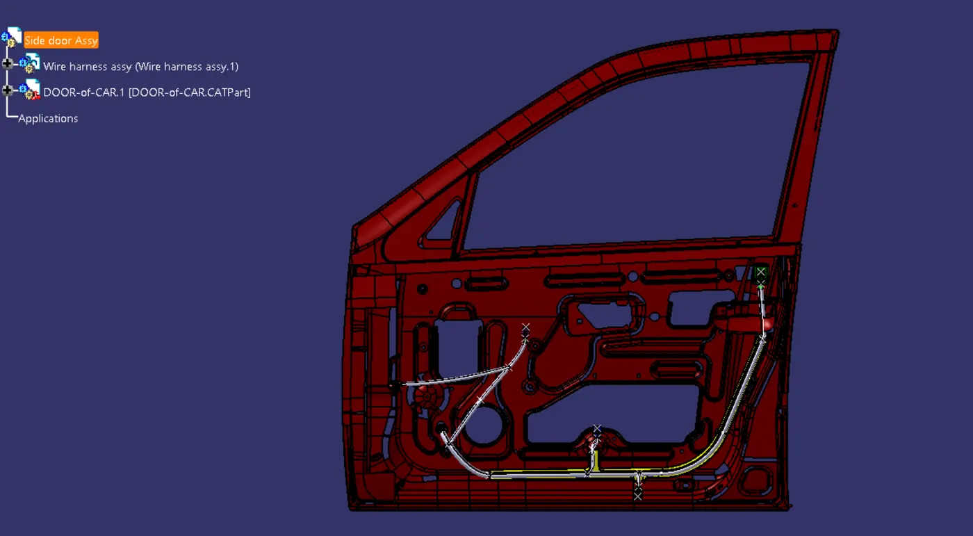
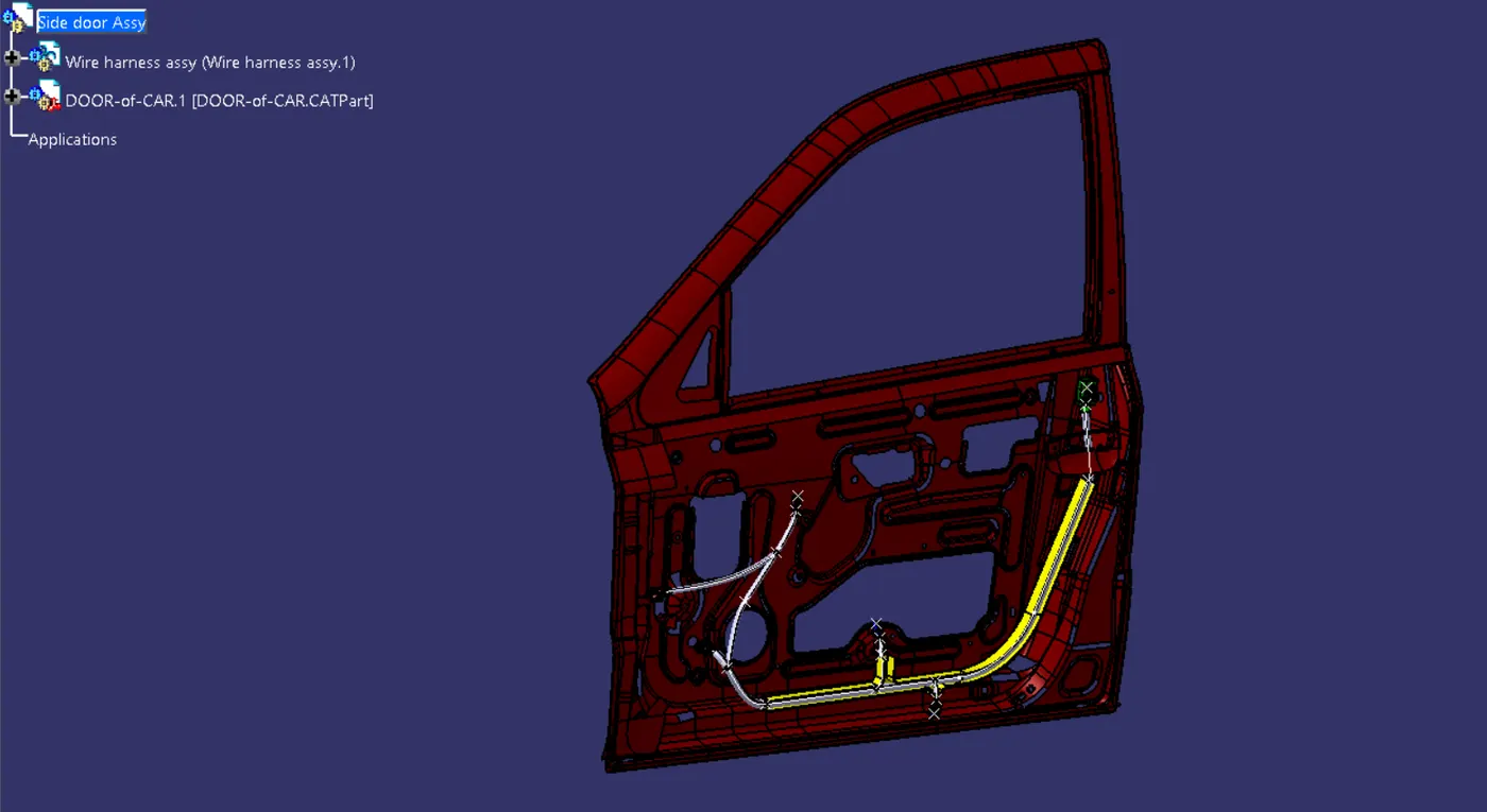
- Now, the car tail gate assembly is ready for the bundle routing as shown in below image
- We have activated Geometrical bundle product file from the context assembly to create new multi-branchables.
- First, we have started bundle routing from interconnection connector to the nearest Mounting clip available and the continue to add multibranchabe bundles to achieve the required harness bundle. Main bundle harness diameter is considered as 15mm.
- Now create branch point to route sub bundle to the Top mount brake light connector. Fir tree clips are added in between the branch point and top mount brake light connector to ensure proper and safe routing. Bundle diameter s considered as 5 mm.
- Add branch point to create bundle connection towards the defogger connector
- Now add branch point for creating sub bundle connection for Wiper motor and number plate connectors.
- Add sub bundle segments with bundle diameter 5 mm.
- Add clip on the sheet metal in between the main harness bundle and number plate connector connections. This will improve the routing and prevent the bundle from unwanted fouling with sheet metal component.
- Now from rh defogger branch point, create gh brake light bundle and create new branck point for LH brake light assembly and create bundles with diameter 5mm each.
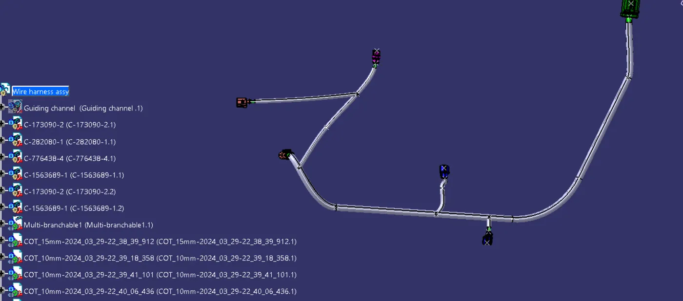
Final geometrical bundle
Step 6 – Applying Protective Cover
After bundle routing, we have to add protective covering to the harness bundle so that it will get protected from the damage.
Harness bundle should be protected with flexible rubber cover at the interconnection region where it is a critical place and subjected to opening and closing of door. There are more possibilities to damage the wiring harness if no proper protection covering is provided.
Step 7 - ELECTRICAL CONTINUITY CHECK
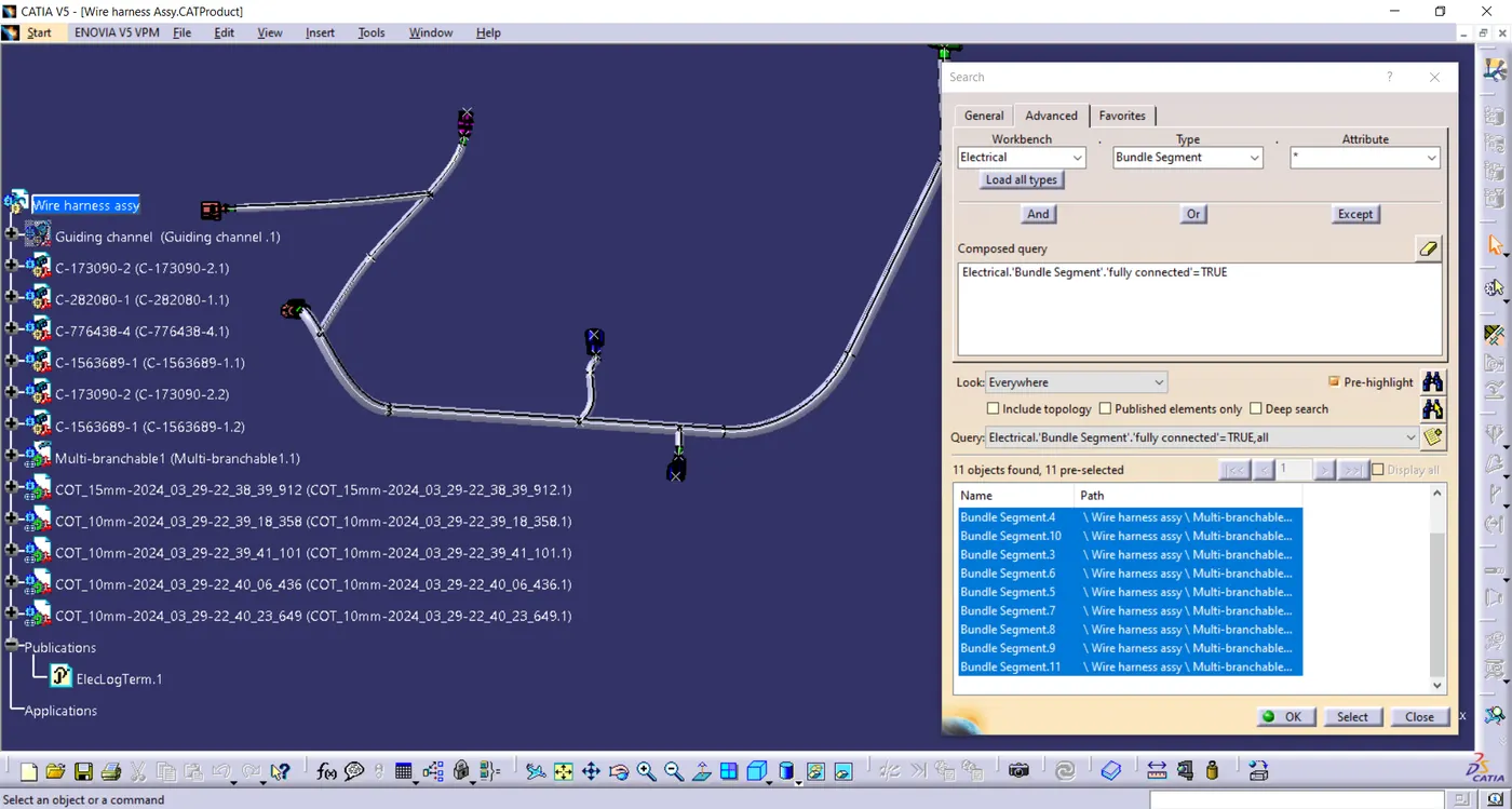
- We need to ensure that the entire bundle is fully connected.
- Go to edit and then click on search command.
- Go to advanced
- Select workbench as electrical, type as bundle segment and attribute as Fully connected
- The select result should be as TRUE or FALSE and the click search to see the connectivity analysis result
For now, we will select "TRUE" and search for results. All the bundle segments are highlighted and found showing that all the bundle segments are electrically connected.
Step 8 - WIRING HARNESS FLATTENING
- Wiring harness Bundle packaging process is done. Now we need to convert the geometrical bundle into a flattened wiring harness in the Electrical Harness Flattening Workbench.
- To create theFlattened Harness, we need to create a new product file and switch into the electrical harness flattening workbench.
- Now we need to define the Harness Flattening Parameters, save it in the same folder with all other files of back door harness project and then Extract the geometric bundle from the wiring harness context product file.
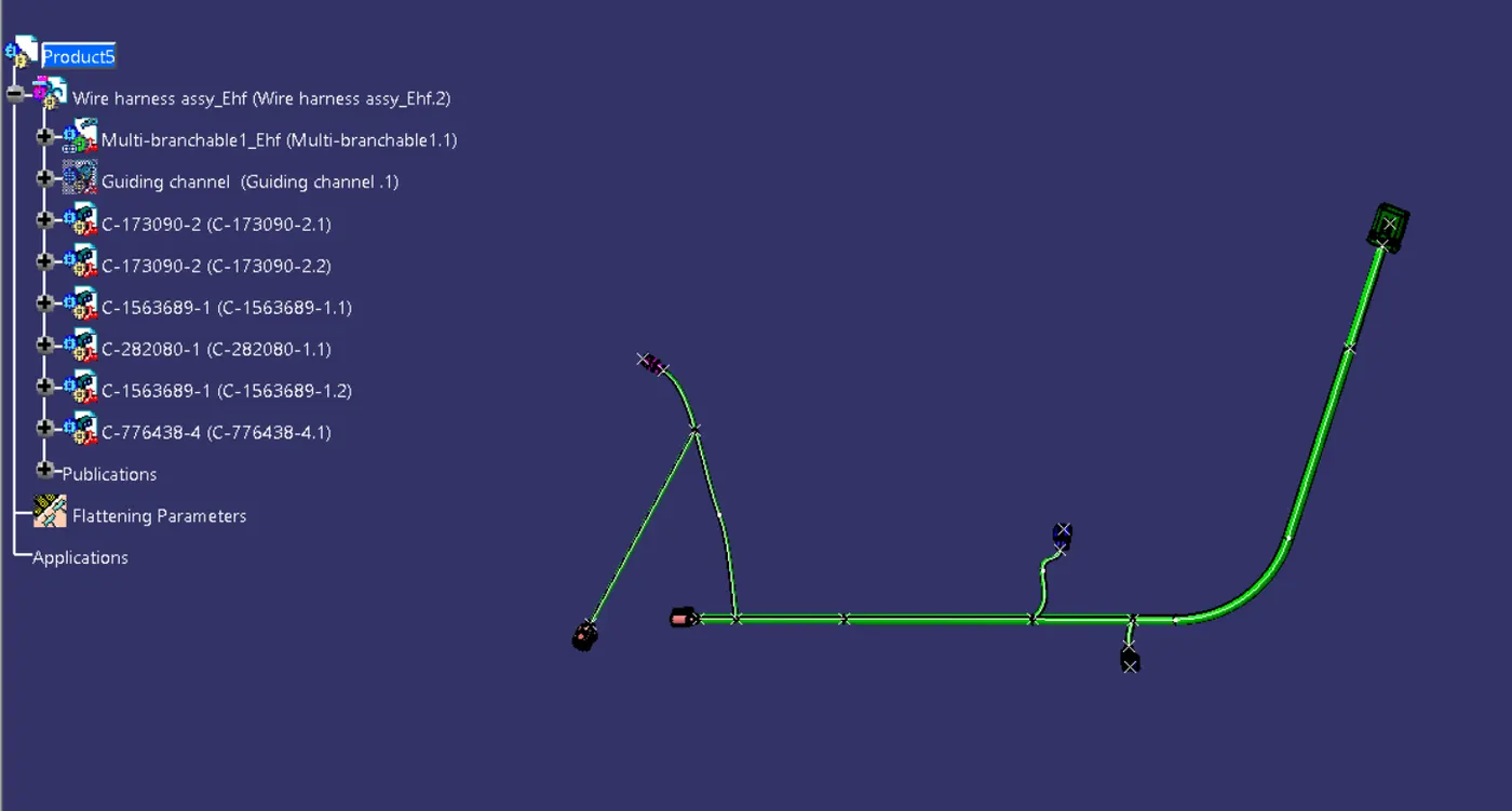
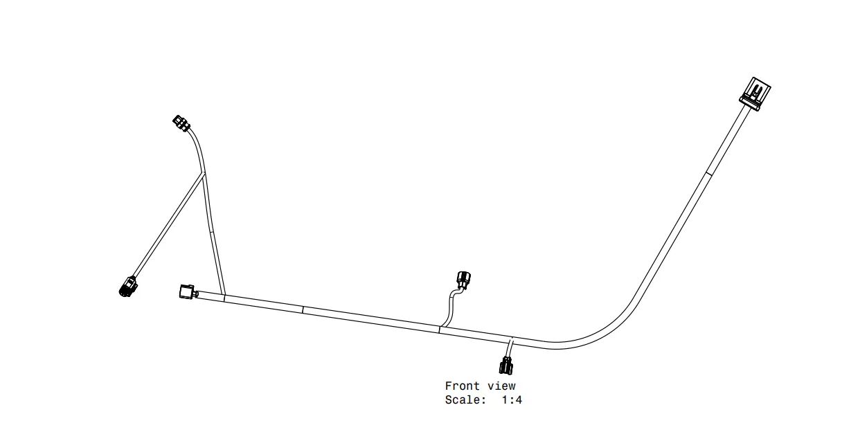
Final Flattened Harness
Insert the flattened harness product into the drawing sheet using view option and selecting the front view command.
Modify the drawing sheet view with required parameters.
Conclusion
CAR front door wiring harness assembly has been successfully completed considering all the packaging rules and industry standards, Wiring harness flattening and Flattened view drawing preparations are also done using CATIA v5 software.