Project 1
Aim: Route the Wiring harness on Given Engine and Prepare flatten view drawing in CATIA V5. Application of all Packaging rules, Industry best practices studied in this course shall be demonstrated in design. Apply Protection coverings as required.
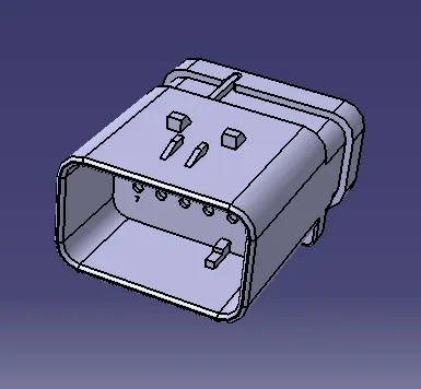
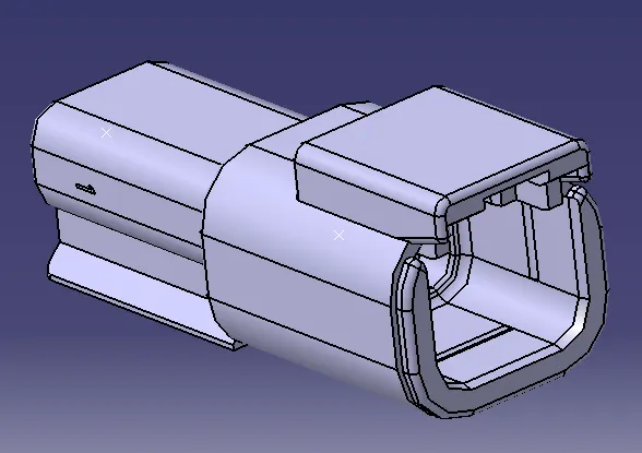
Connectors were used to create wring harness designs. These connectors were defined electrically to create harness.
Images of Connectors
To support wiring harness support elements were introduced in asssembly.
Here are aome examples are given: Support rail top & bottom, P-Clamp, Fur tree Clip, L- type clamp
These elements are used to give proper rounting direction and to avoid body contact from nearby object to avoid short circuit for the same.
Images of support elements
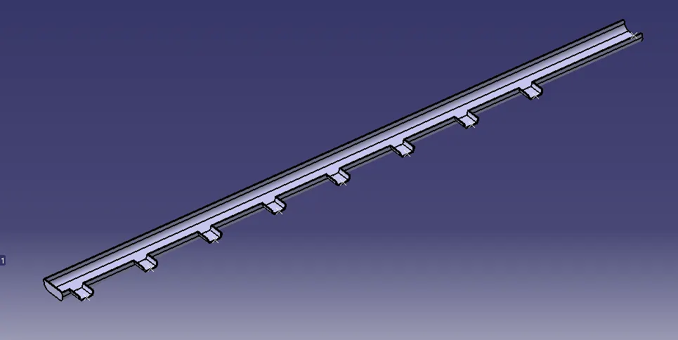
Bundle Connection Protection Rail Top
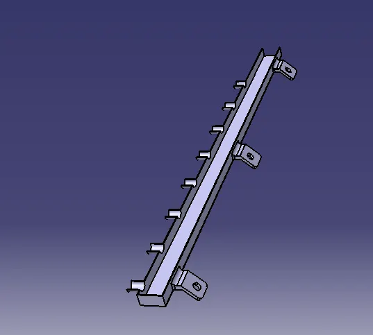
Bundle Connection Protection Rail Bottom
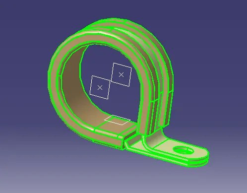
P Clamp
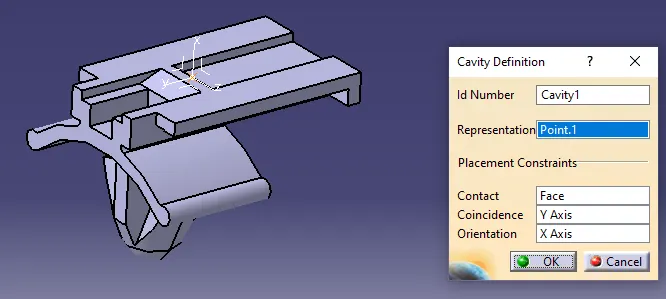
Clip
Protective Coverings are used to provide external protection to wire bundle from foreign material and moisture also.
Conduit Tubes
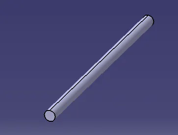
Wiring Harness
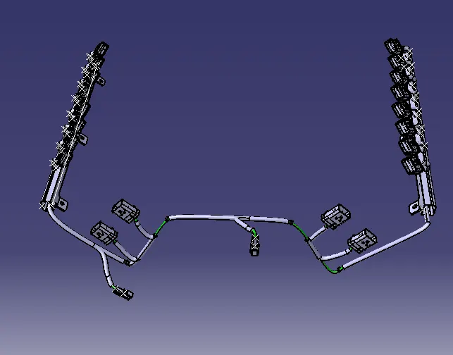
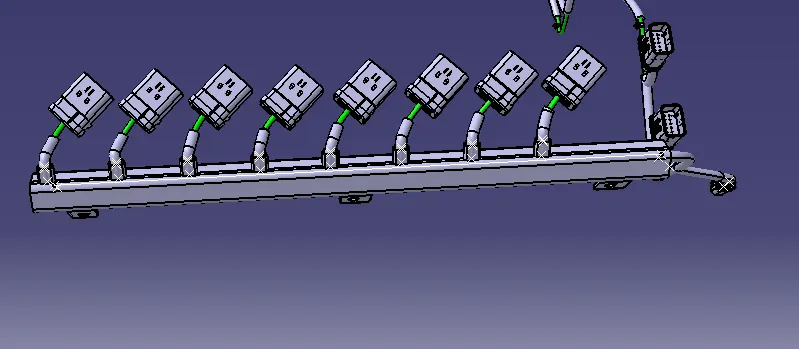
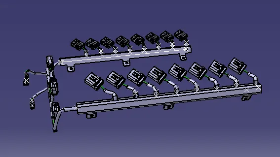
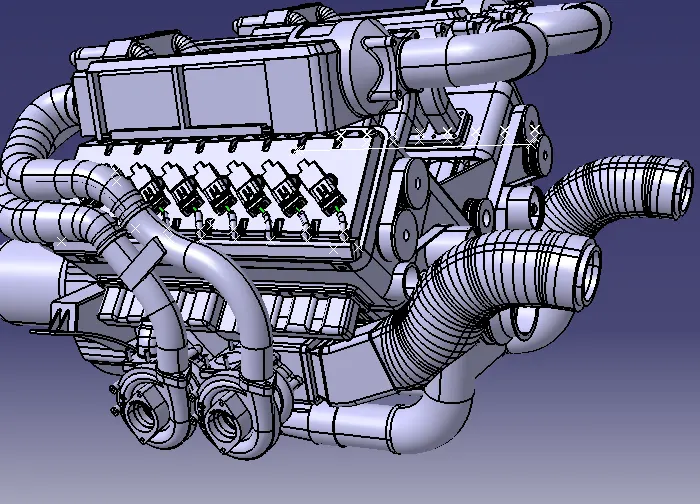
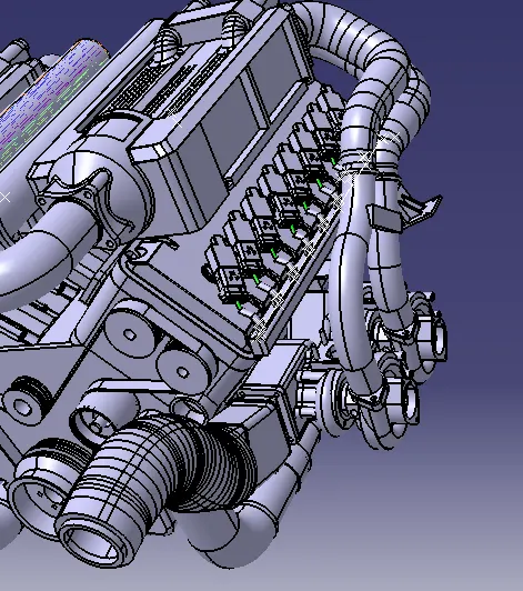
These harness was designed using wiring harness assembly environment. The bundle was define geometricaly to initiate bundling. After that branches were made using connectors and connection points.
To give proper shape for routing supporting elements were used.
Here is snap shot of wiring Harness.
Wiring Harnness Connectivity check:
The cconnectivity is checked for continuity in harness.
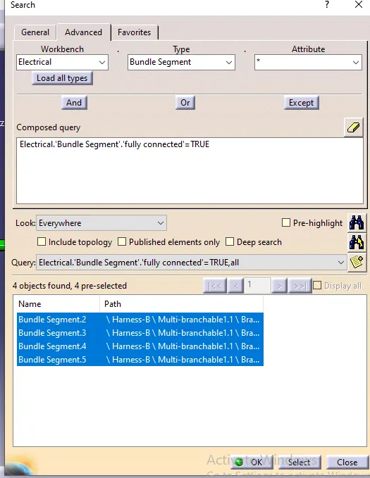
Continuity check
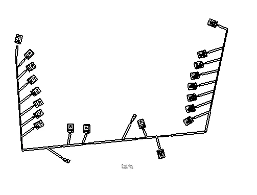
After completing continuity check wiring harness is flattened using wiing harness flattening workbench. By using various commands harness is flattened in 2-D representation.
Flattened view and drawing view are given below:
Flattened View of wiring harness
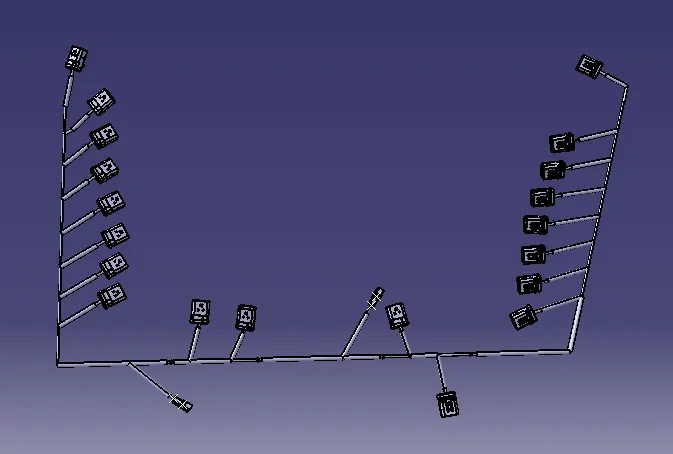
Drawing View