Project 1
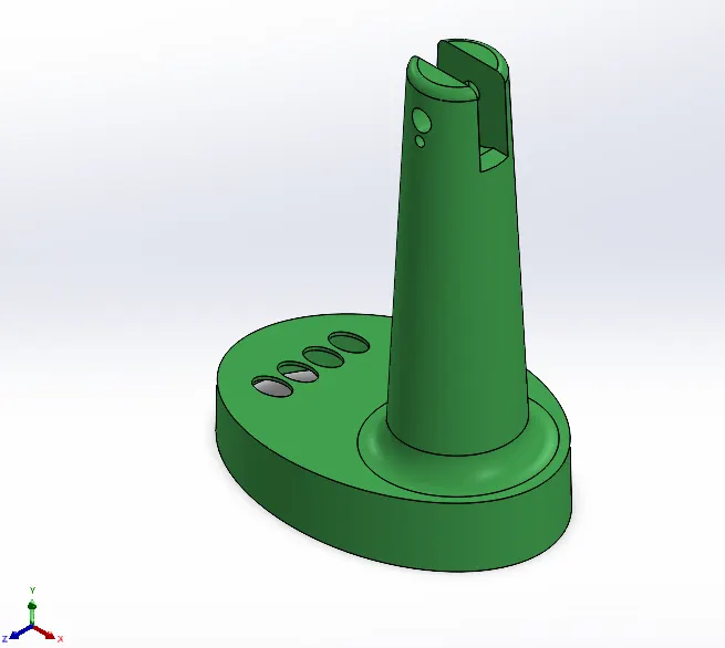
TABLE FAN BASE MOLD ASSEMBLY:
INPUT:
OUTPUT:
Procedure of Core/Cavity block for TABLE FAN BASE:
- Component is SCALED as per the product shrinkage percentage (in this case 0.6%) and DRAFT ANALYSIS is performed so that parting line can be forme
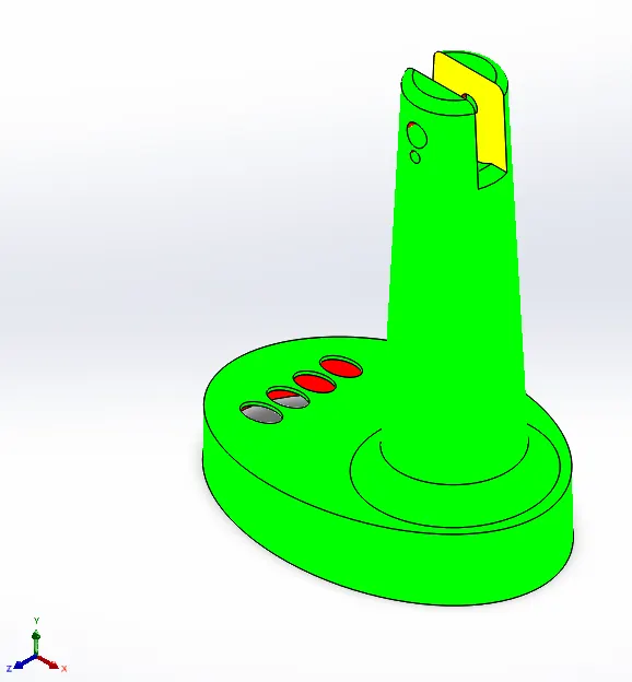
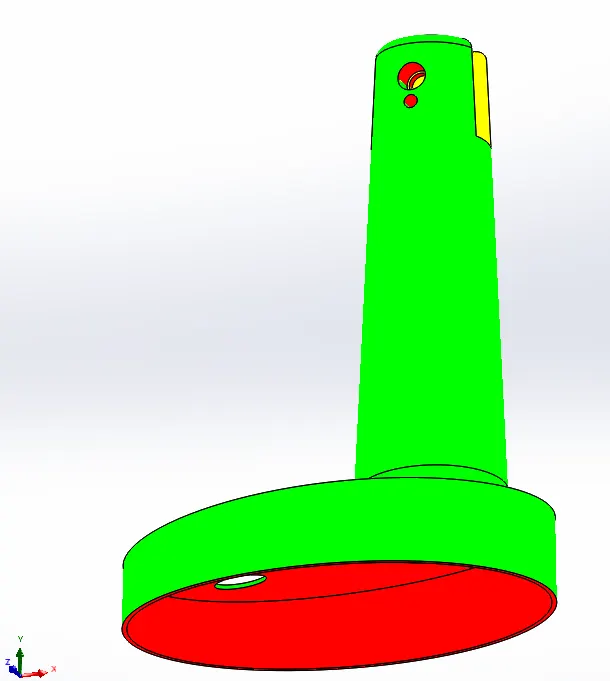
- PARTING LINE is formed
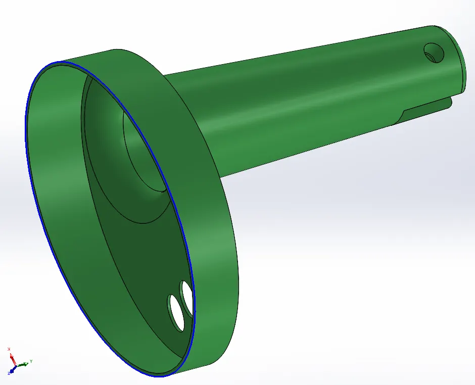
- Through holes are covered for forming Core and Cavity surfaces using SHUT-OFF SURFACES command.
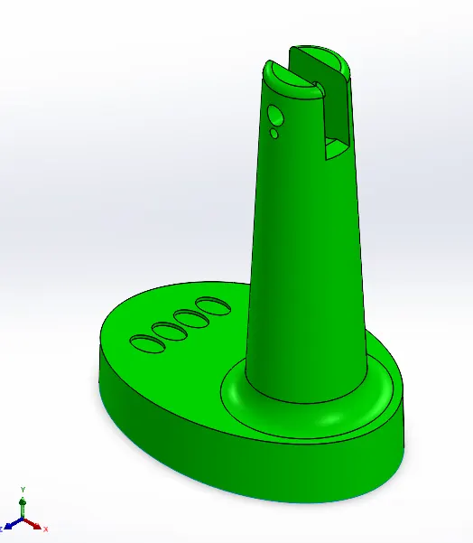
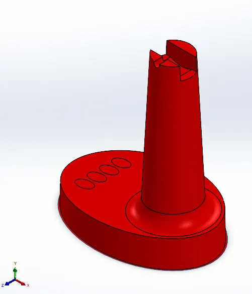
- SPLIT LINES are formed on the core surfaces coinciding with parting line.
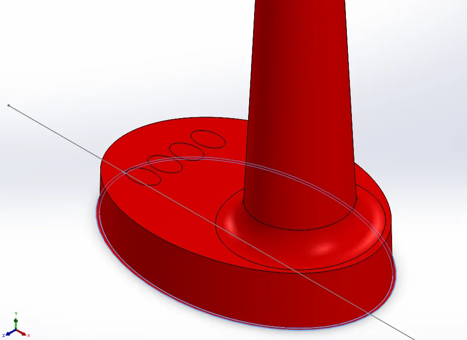
- PARTING SURFACE is created using RULED SURFACE command and then further joining all surfaces.
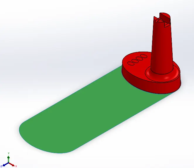
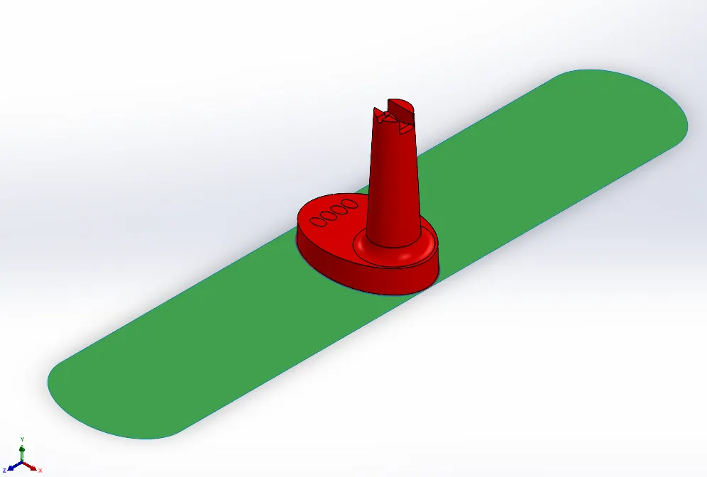
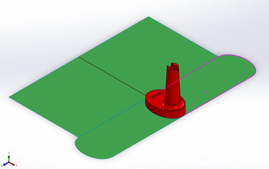
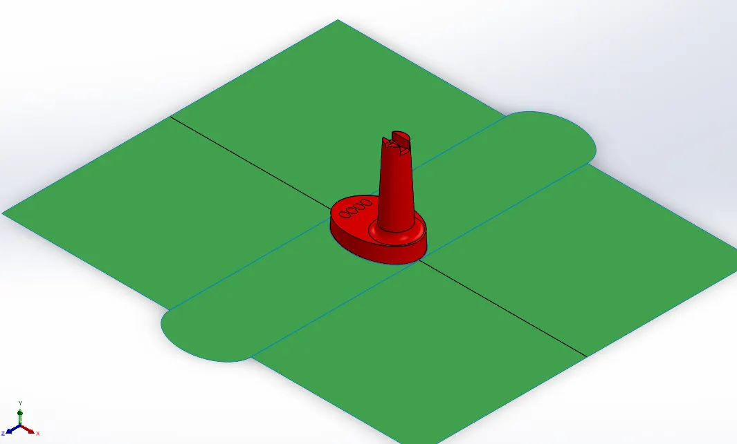
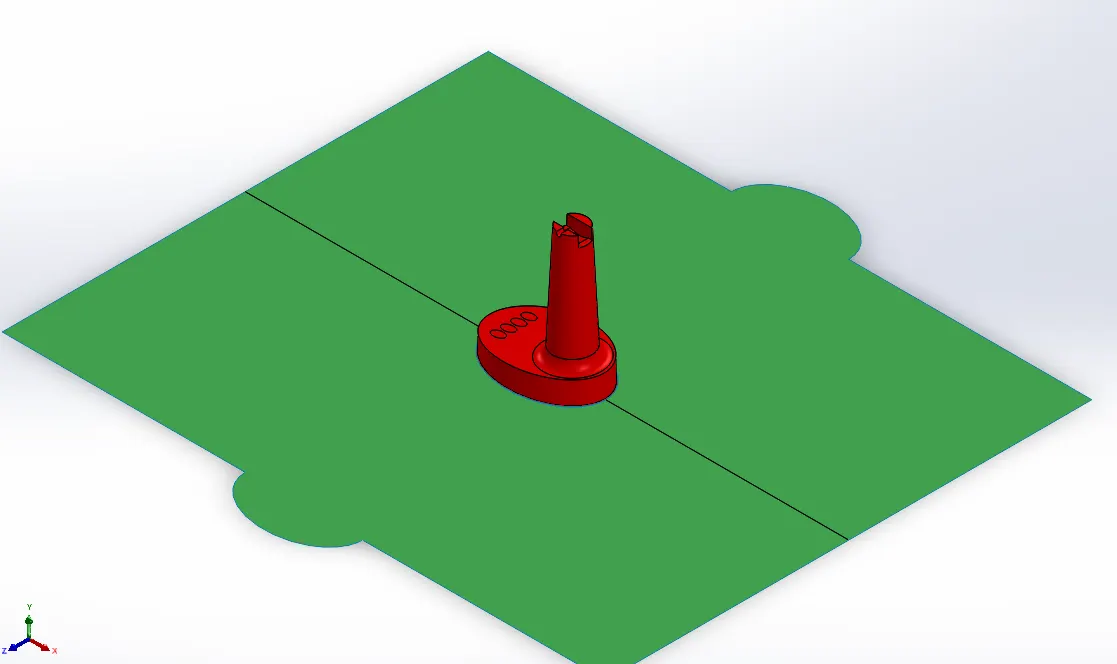
- A duplicate is made using MOVE/COPY BODIES command and each one is knitted with Core and Cavity surfaces respectively.
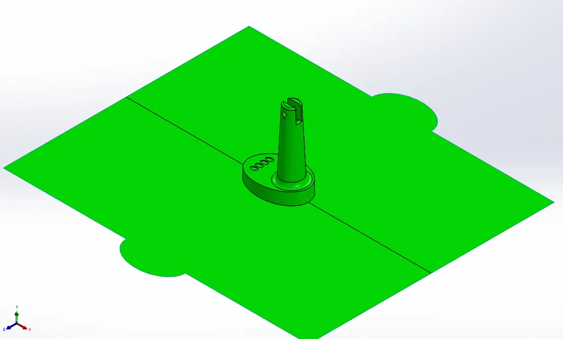
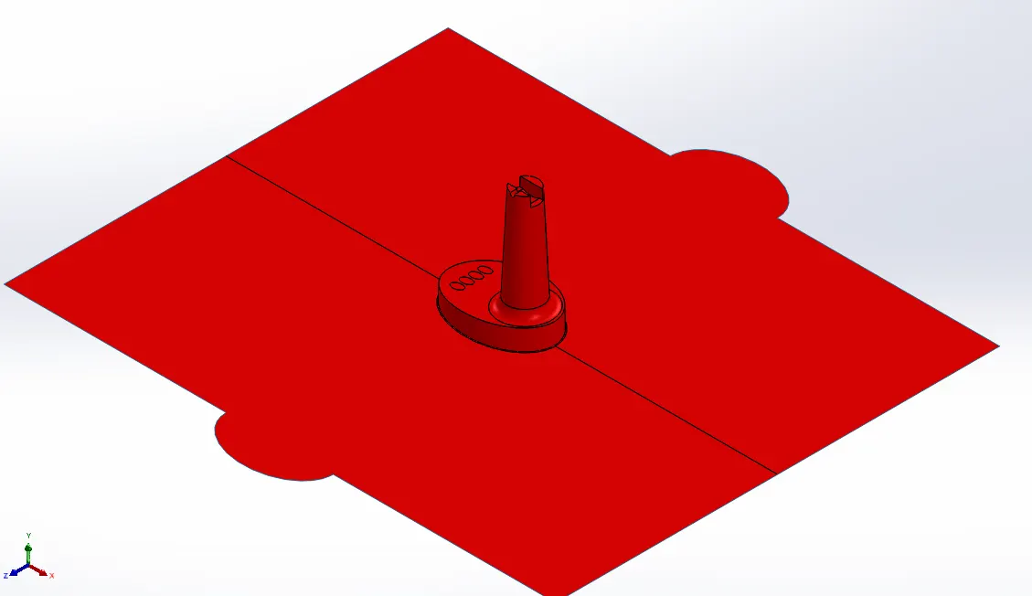
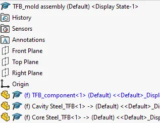
- Component is inserted into an Assembly for Mold parts. In that assembly, Separate core and cavity parts are created.
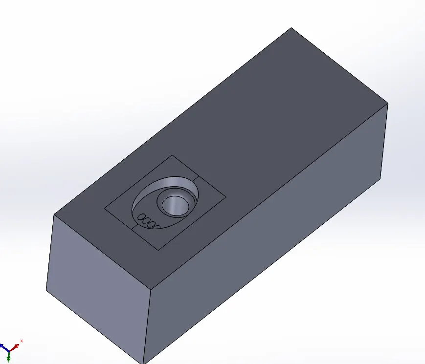
- Two separated sketches are created considering Cavity surface in CAVITY STEEL Part. Outside sketch (Sketch1) is for Planar surface and inside (Sketch2) is for Non-planar surfaces.
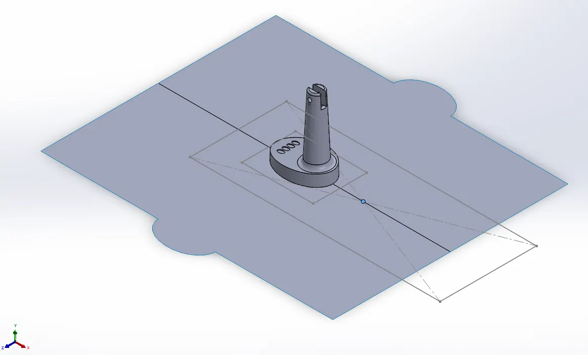
- Using Sketch1 as input a block is created and the block is splitted using Sketch2. Further the inner block using CUT WITH SURFACE command is cutted to form cavity.
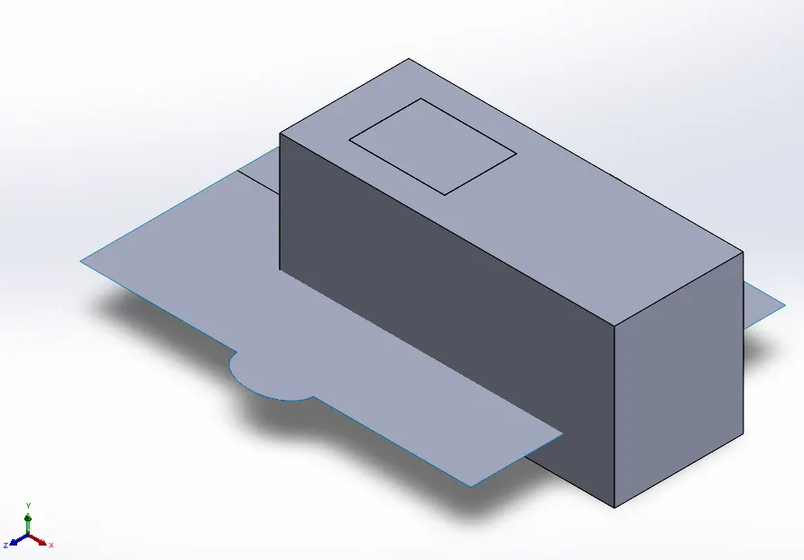
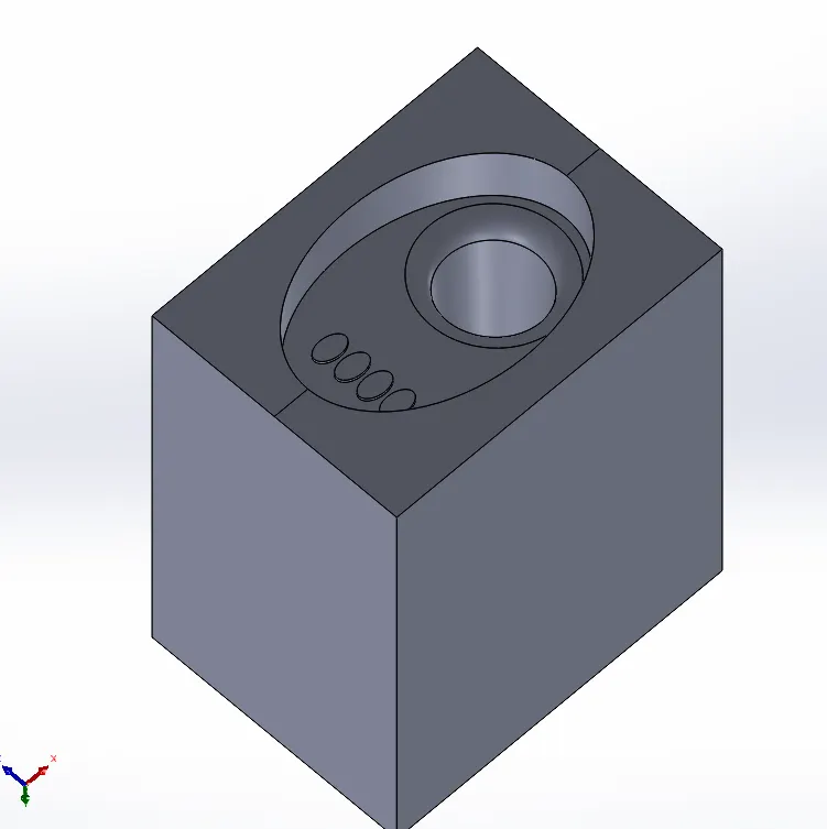
- Outside is leveled with inside block using MOVE FACE command. Then joined with inside cavity using COMBINE command to formed final Cavity block (in Green).
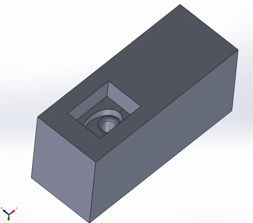

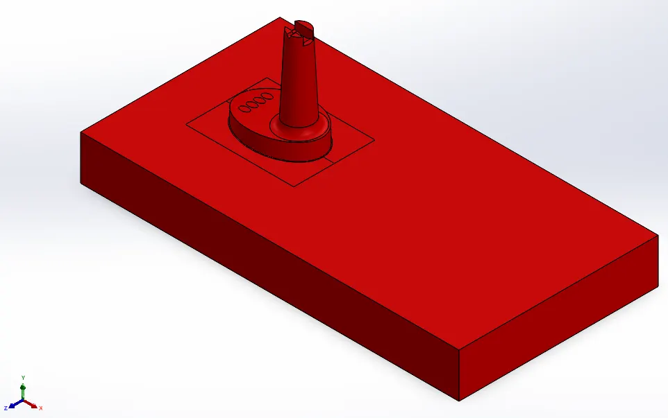
- Using similar from Step 8 to Step 10 core block is formed.
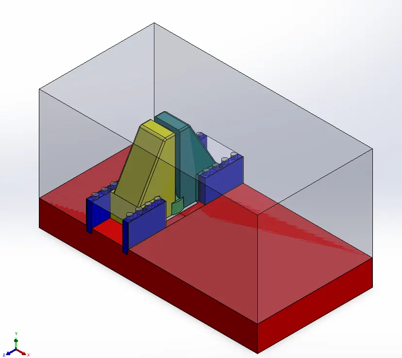
Procedure of Slider1 (Yellow) and Slider2 (Grey) for TABLE FAN BASE:
- Sketch is created so that slider can be separated from cavity using SPLIT command.
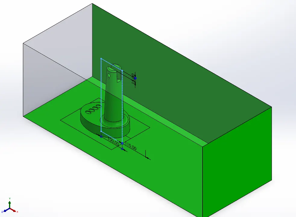
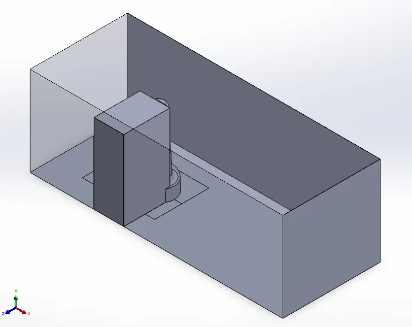
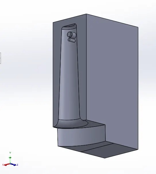
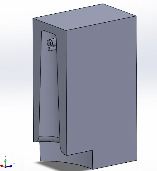
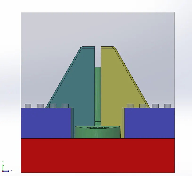
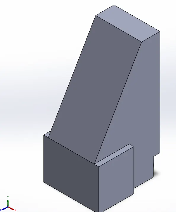
- Slider is then modified as per requirements. 30 deg Chamfered upto 2/3rd of vertical length making sure at least 40mm space at the top surface in direction of slider motion and also material is added onto side upto chamfered edge for achieving constraint sliding of slider.
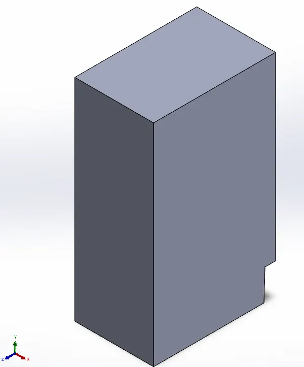
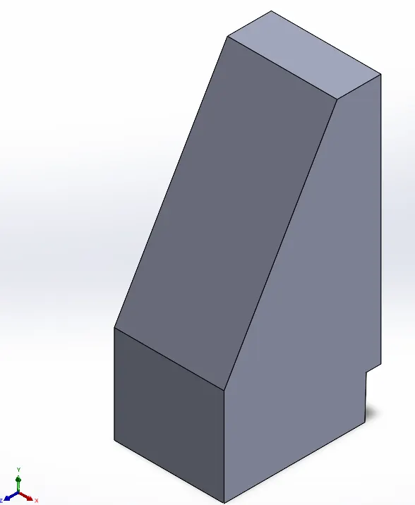
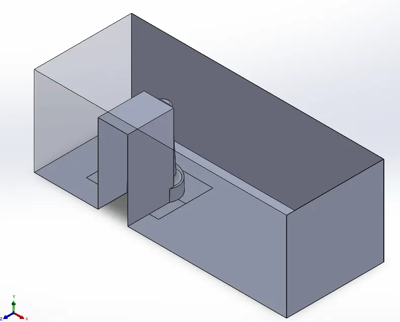
- Cavity block is modified for accomodating slider modifications.
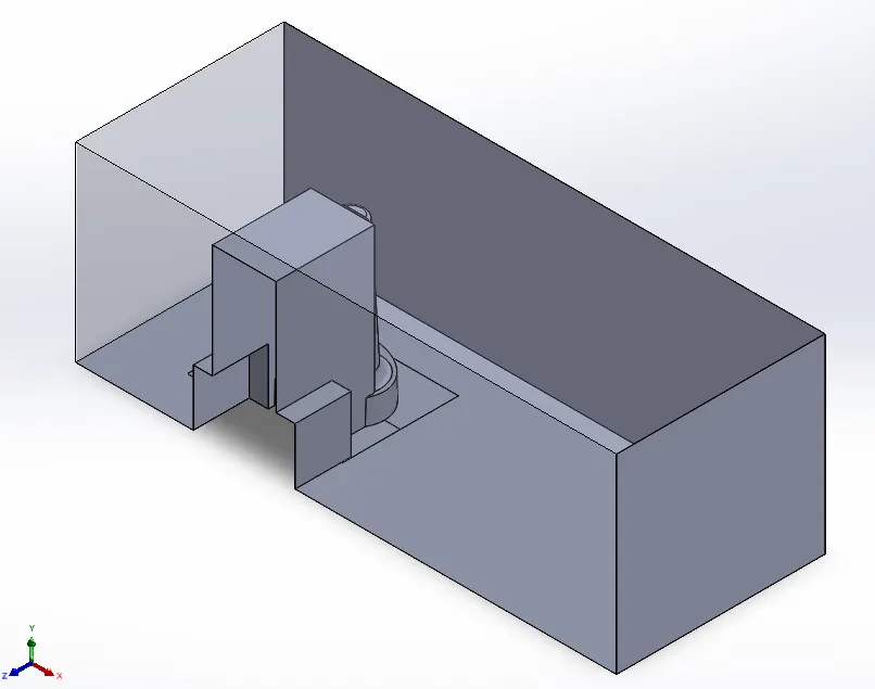
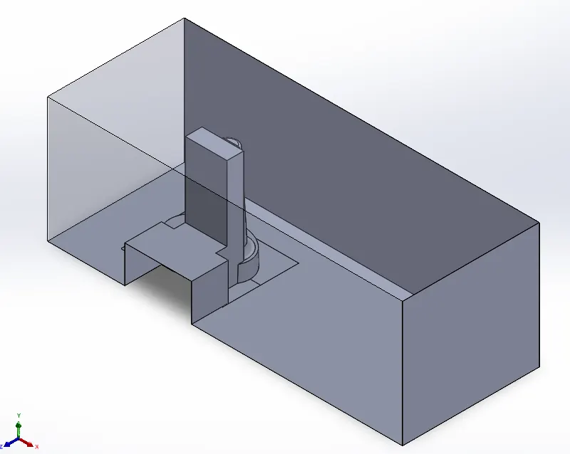
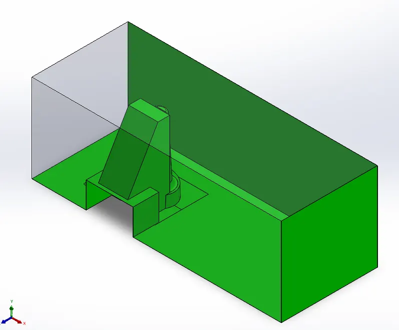
- Fillets are provided at suitable edges.
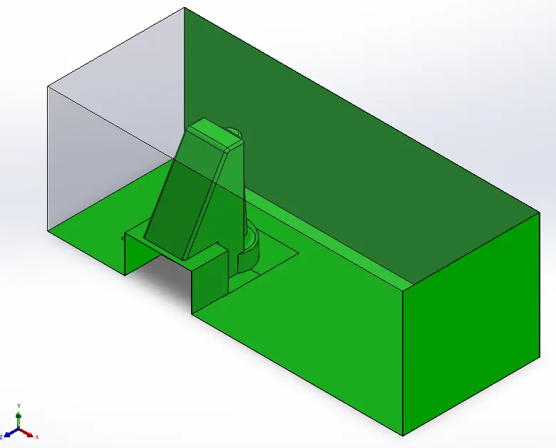
- Now slider body is inserted into new part in mold assembly by name of SLIDER1.
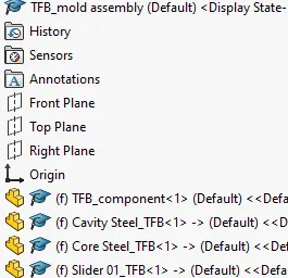
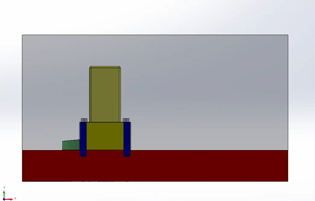
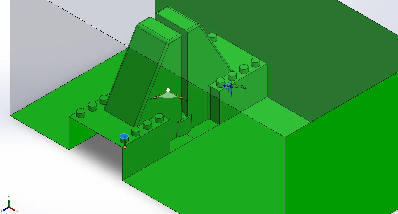
- Now in core block walls are extruded for constraining slider motion.
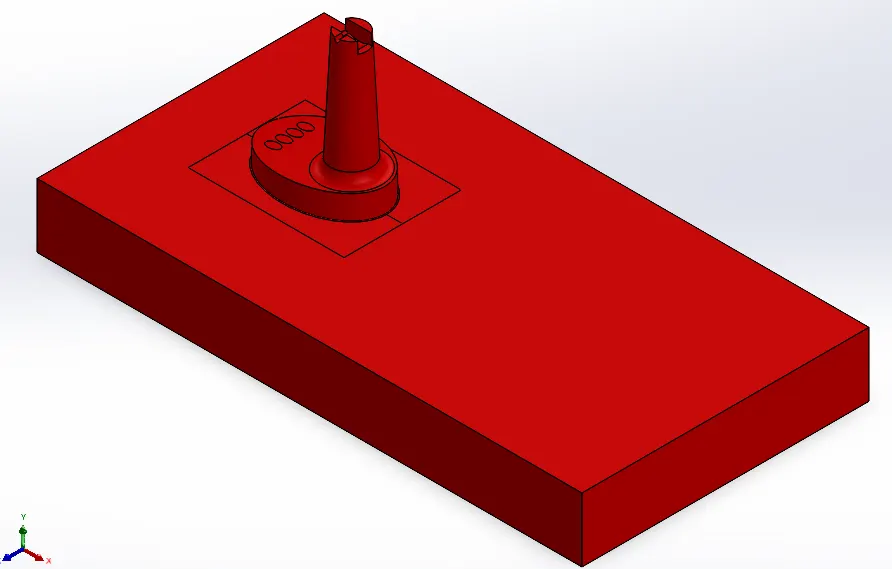
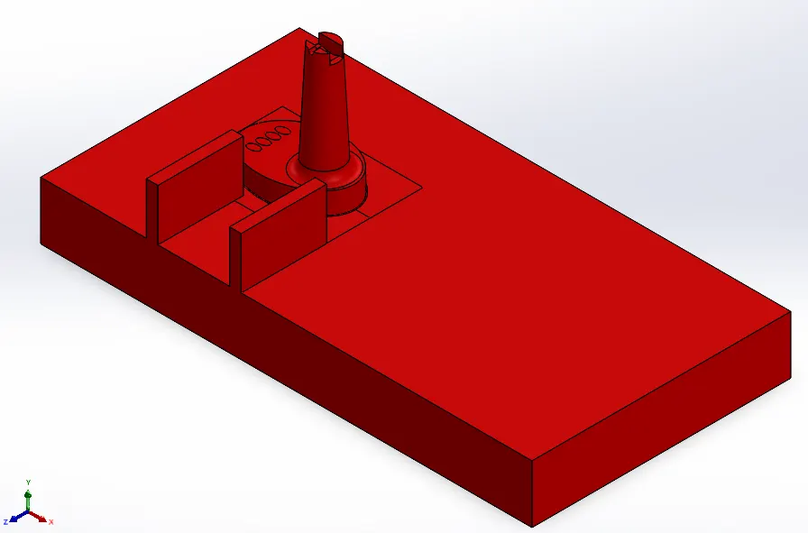
- Slot is created on either side for limiting slider motion.
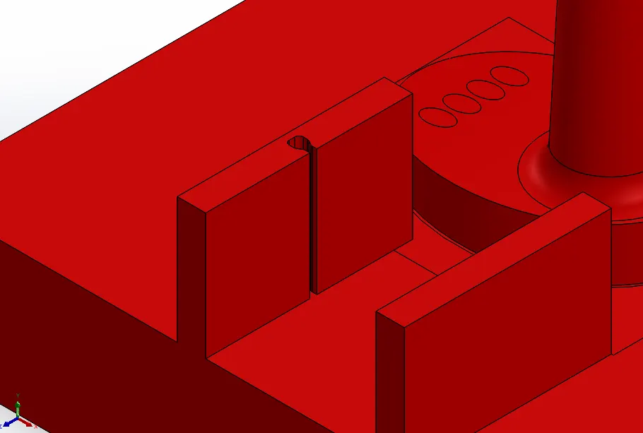
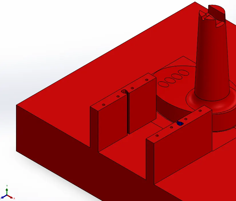
- M6 Tap hole are created on walls for bolts and washers so that slider motion can be constrainted.
- Slider2 is also created using similar steps as slider1.
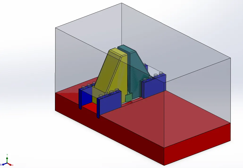
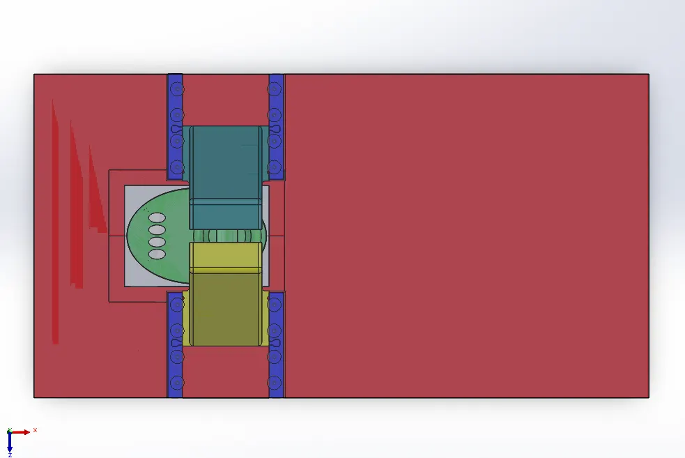
- Space for bolts (highlighted) is impressioned upon the cavity block with clearance of 1mm all around.
Core modifications for ease of manufacturing and Ejection arrangements of Mold parts:
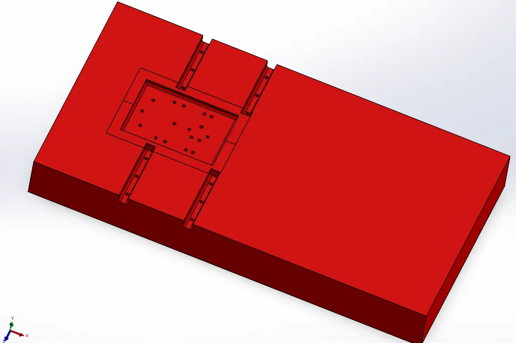
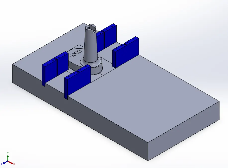
Slider walls and Component is changed into inserts so that machining time as well as material cost can be saved.
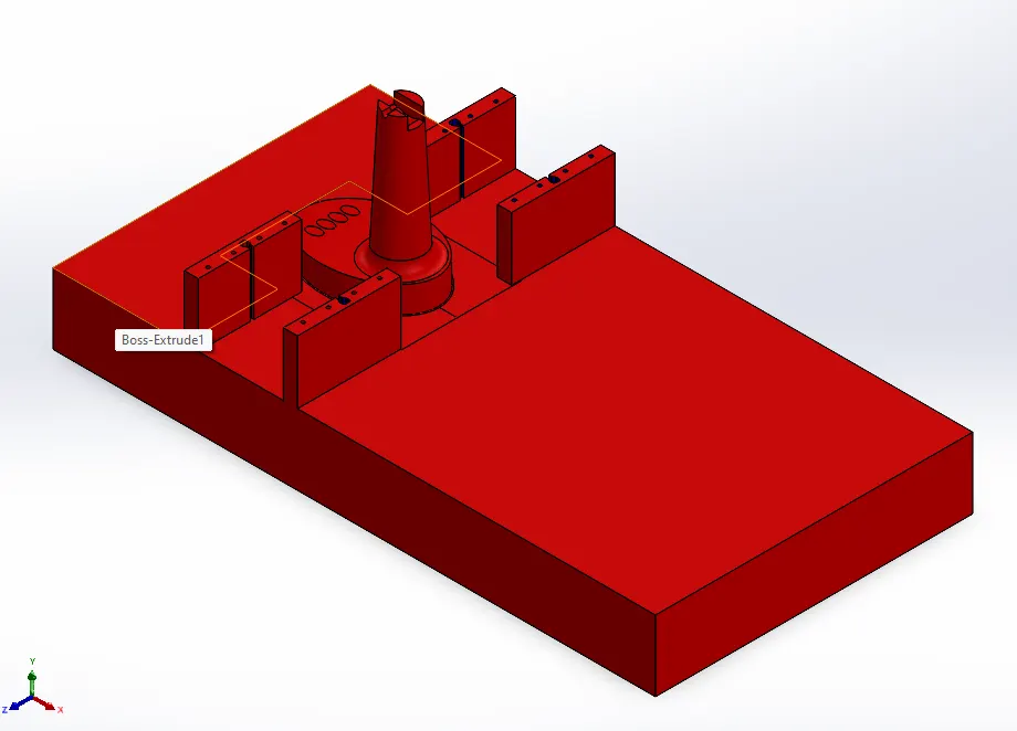
Blue colored inserts are for Slider walls.
Core Block: Red
Slider wall inserts: Blue
Component bosy insert: White
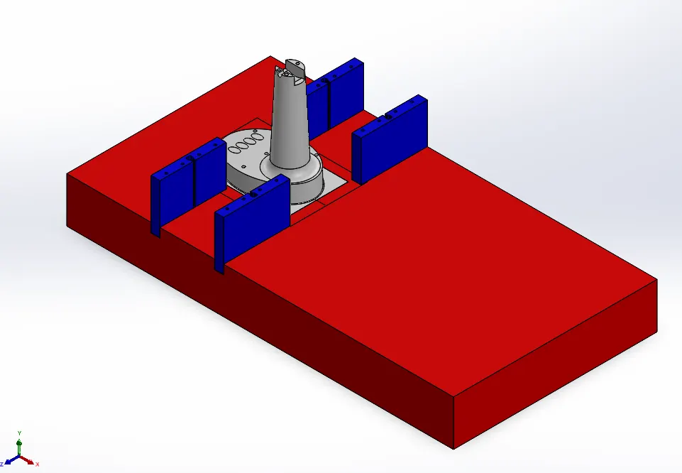
Only the depressed surfaces need to machined in the core block and also height of core block required is also significantly reduced.
The inserts can be machined separately.
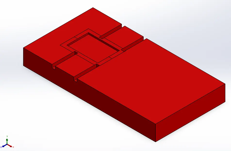
Hole for fixing inserts were provided.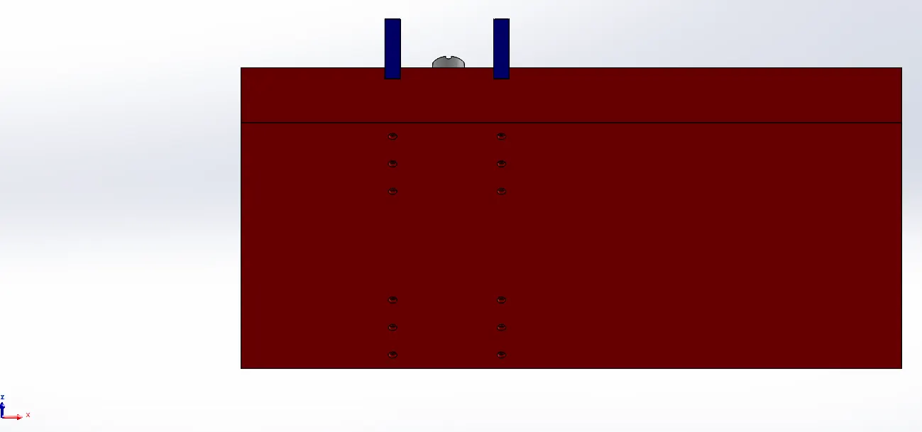
EJECTION PINS (black) are provided evenly throughout the component.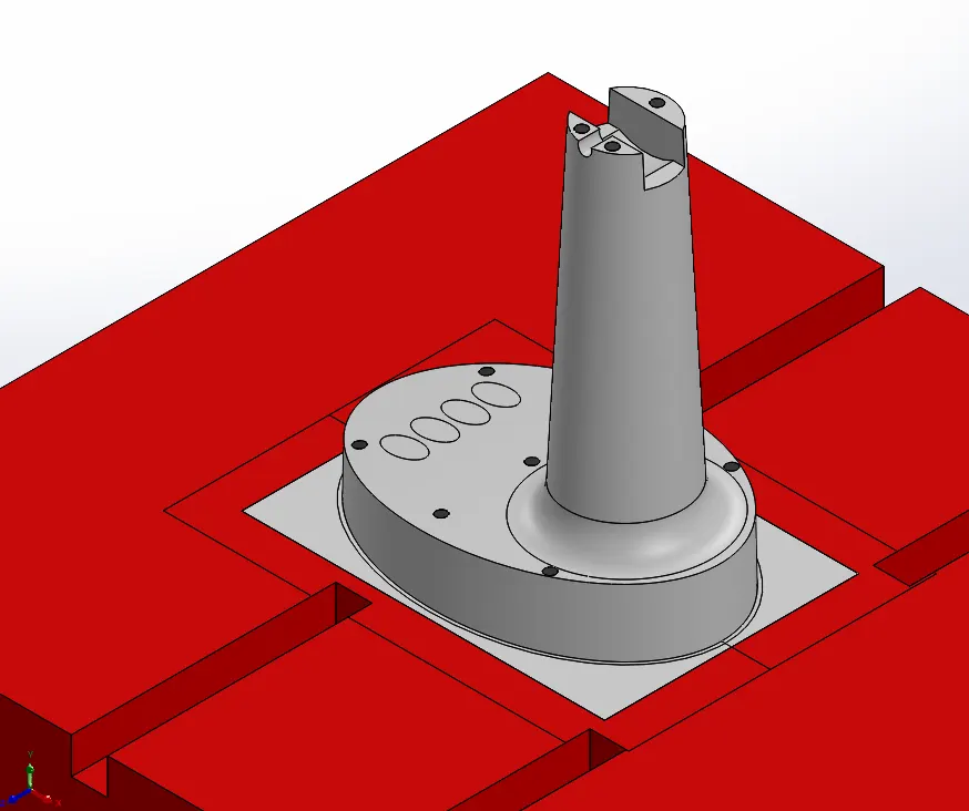
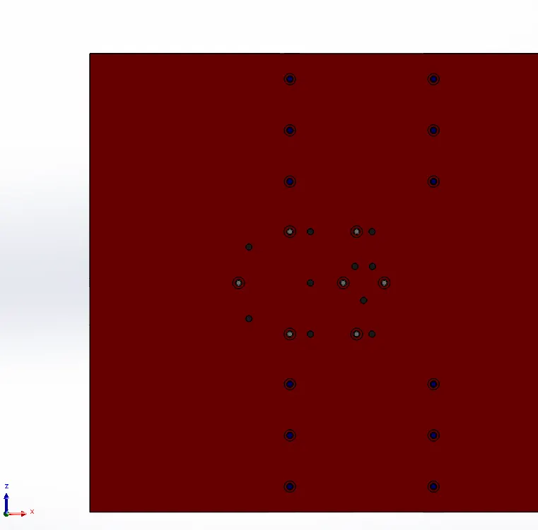
Bottom view shows the Counter bore holes for fixing inserts and Ejections pins for component ejection.
Maximum permisible fillet is applied for reducing machining time by allowing use of high diameter cutter.