Project 1
1. Design a battery pack for a car roughly 150 Kw with 120 V. Use 3500 mAh 3.6V nominal NMC chemistry cell.
a. Design the battery pack configuration.
b. Draw the BMS topology for this battery pack.
a.) Design the battery pack configuration.
Cell Specifications:
Nominal Voltage = 3.6V
Max. Voltage = 4.2V
Nominal cell capacity = 3500mAh = 3.5 Ah
Rated power = 150KW
Rated voltage = 120V
The required motor current= (rated power *1000)/rated voltage
= (150*1000)/120
=1250A
Number of cells in series = total voltage /cell nominal voltage
Assuming the max voltage as the total voltage
Number of cells in series = 120 /3.6
Number of cells in series = 33.33
Rounding off the number of cells in series depends on
- Maximum voltage
- Minimum voltage
Case-1
Rounding off 33.33 to 33
Nominal battery voltage = cell nominal voltage * 33
= 3.6 * 33 = 118.8V
Maximum battery voltage = cell max voltage *33
= 4.2*33 = 138.6 v
Minimum battery voltage = cell minimum voltage * 33
= 2.7 *33 =89.1V
Case-2
Rounding off 33.33 to 34
Nominal battery voltage = cell nominal voltage * 34
= 3.6 * 34 = 122.4V
Maximum battery voltage = cell max voltage * 2
= 4.2*34 = 142.8v
Minimum battery voltage = cell minimum voltage * 2
= 2.7 *34=91.8V
rounding to 33 doesn't satisfy the vehicle's requirement of 120V as the nominal battery voltage only comes as 119V so we will go with case-2 that is with 34 cells in series.
The excess 2.4 V can be adjusted by using a DC-DC Buck converter.
Now we will calculate the number of cells needed in parallel:
Number of cells in parallel = Total current/cell nominal capacity
Number of cells in parallel = 1250/3.5 = 357.14
Case-1 : rounding to 357
Maximum current that can be supplied = 357 * 3.5 = 1249.5A
It can be adjusted to 1250A using a current transformer.
Hence the needed battery pack configuration is 34S 357P.
b.) Draw the BMS topology for this battery pack.
For the above battery pack we have to draw the BMS topology based on number of cells connected in series so the number of cells is 34 cells so the cells are more than 18 then we use master & slave topology
In this topology we using daisy chain interface means that all data of slave-1 is sent to slave-2 & slave2 collects the 34 cells data and sends it to micro controller unit. The topology is shown below: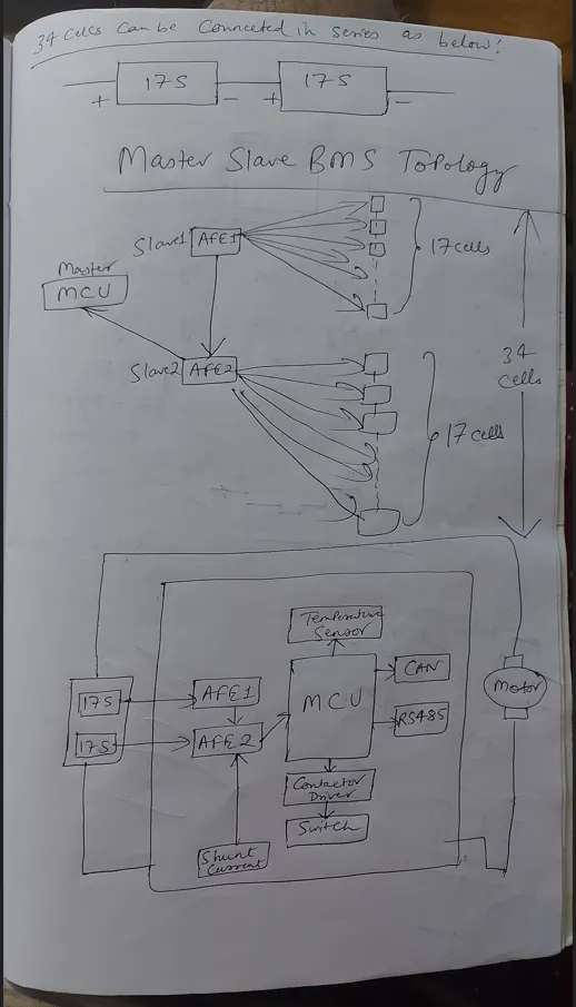
2. Build a 3S2P battery pack configuration with generic battery block using Matlab/Simulink.
Total number of cells in battery pack = no.of cells in series * no.of cells in parallel
= 3*2
=6 cells
Series connection of a battery:
Batteries are connected from teminal to terminal in a way that the +ve terminal one battery is connected to -ve termnal of the other battery and -ve terminal of one battery is connected to +ve terminal of other battery.
Parallel connection of a battery:
Batteries are connected from terminals to same terminals of the other batteries that is +ve terminal of one battery is connected to +ve terminal of other battery and -ve terminal of one battery is connected to -ve terminal of other battery.
The battery pack model is shown below:
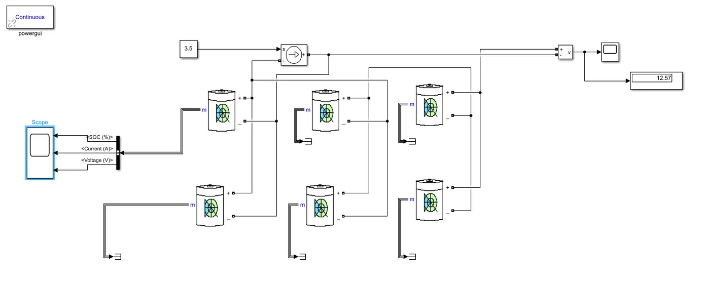
Model explanation:
The voltage is measured by using voltage measurement and is connected across the battery pack and the scope is connected to bus selector and is connected to battery measurement port for measuring the SOC,voltage & current of the cell the constant block is connected to controlled current source and is given load to the battery pack.
Battery parameters are selected as shown below:
Nominal voltage of cell = 3.6v
Rated capacity of cell =3.5Ah
Maximum voltage of cell =4.2v
Total number of cells in a battery pack = no.of cells in series * no.of cells in parallel
= 3*2 = 6 cells
Nominal voltage of the battery pack = no.of cells in series * nominal volatege of a cell
Nominal voltage of the battery pack = 3*3.6v = 10.8v
Rated capacity of battery pack = no.of cells in parallel * Rated capacity of a cell
= 2*3.5
Rated capacity of battery pack=7Ah
Overall voltage of the battery pack=maximum capacity of the cell*no.of cells in series
=4.2*3
Overall voltage of the battery pack =12.6v
Some terms & its meaning used in the above challenges:
Capacity: The capacity of a battery or cell is defined as the amount of energy that it can deliver in a single discharge. Battery capacity is normally specified in amp-hours (or milli-amp-hours) or as watt-hours.
Cycle Life: The capacity of a rechargeable cell or battery changes over its life. The definition of the battery life or cycle life of a battery is number of cycles that a cell or battery can be charged and discharged under specific conditions, before the available capacity falls to a specific performance criteria - normally 80% of the rated capacity.
Rated Capacity: The capacity of a battery is expressed in Ampere-hours, Ah and it is the total charge that can be obtained from a fully charged battery under specified discharge conditions
Results :
After running the model the voltage changes like shown below from 12.6 V to 12.157V.
The voltage is dropped from 12.6v to 12.57v for this battery pack.
Cell level SOC,Current & voltage are shown below:
First plot shows SOC of the cell it is dropped from 100% to 99.86 %
Second plot shows Current of the cell it is nearly 1.8A
Third plot shows voltage of the cell it is dropped from 4.180v to 4.155volts