Project 1
AIM
Design a G+6+R Residential Building located in Bangalore using STAAD Pro Connect Edition.
INTRODUCTION
STAAD is a comprehensive structural finite element analysis and design application that provides powerful visualization capabilities and a wide range of international design codes. Using an easy-to-use intuitive interface, engineers can automatically convert physical models into analytical models for a more streamlined workflow while conducting structural analysis. STAAD makes it easy to integrate structural analysis into a BIM workflow and share synchronized models for multi-discipline collaboration. STAAD’s powerful analysis capabilities allow it to perform analysis on any structure exposed to static, dynamic, wind, earthquake, thermal, and moving loads.
PROCEDURE
1. Model creation
Nodes and Beams are generated as follows.
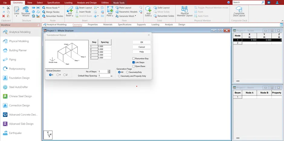
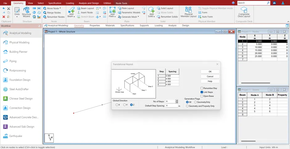
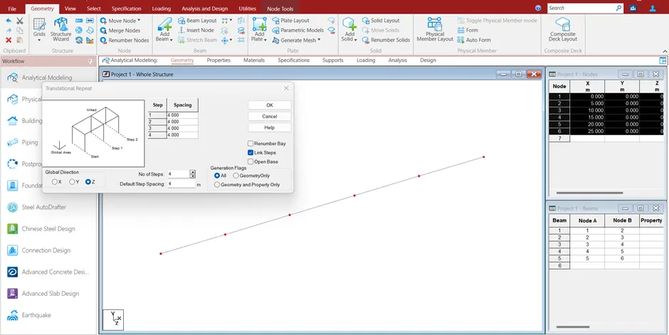
Nodes for the Ground floor are created.
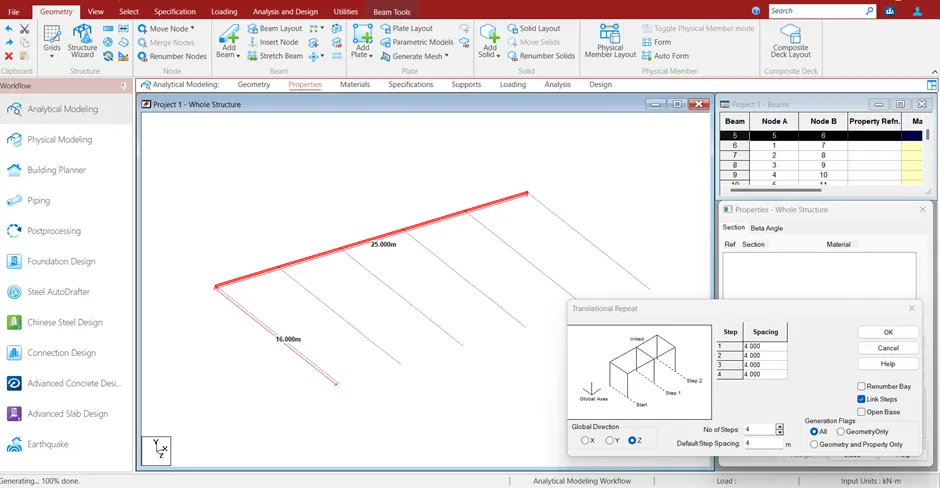
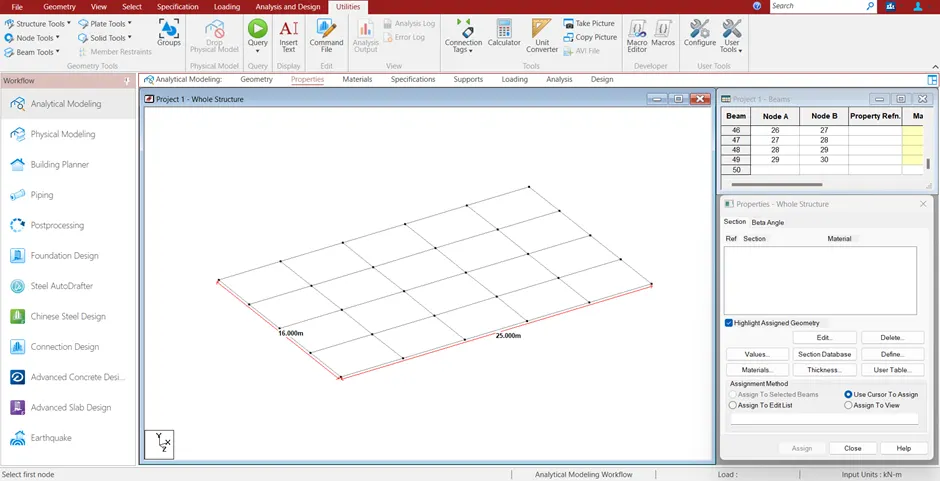
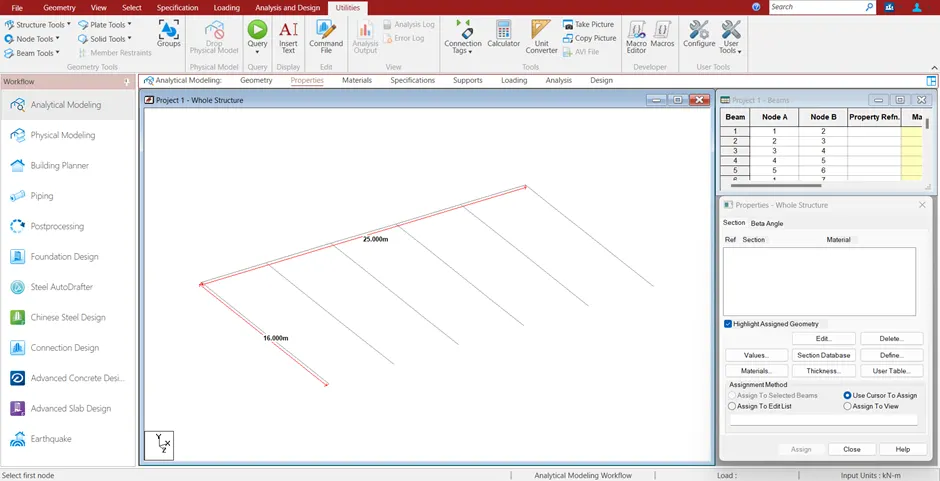
The Ground floor is created by creating nodes and beams.
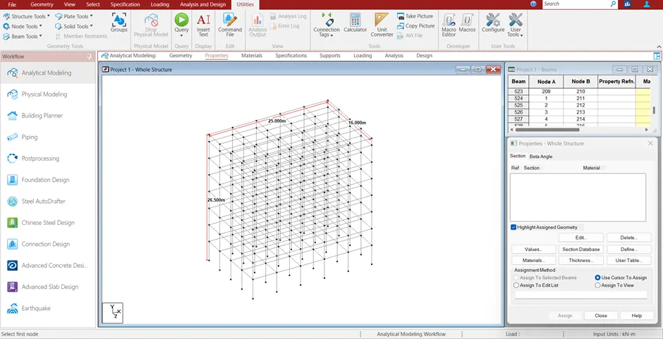
The Whole structure is created by using Translational repeat.
Height of building = 4+6x3.5+1.5
= 26.50m
2. Adding Restraints
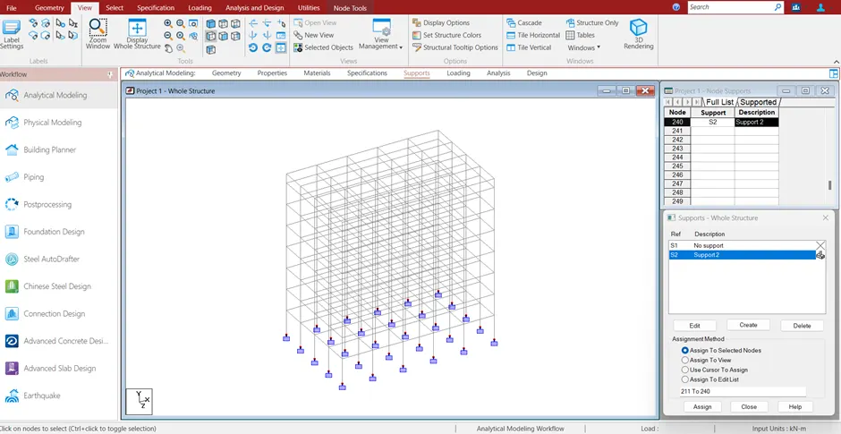
Fixed joints are added.
3. Assigning Properties to Beam and Column
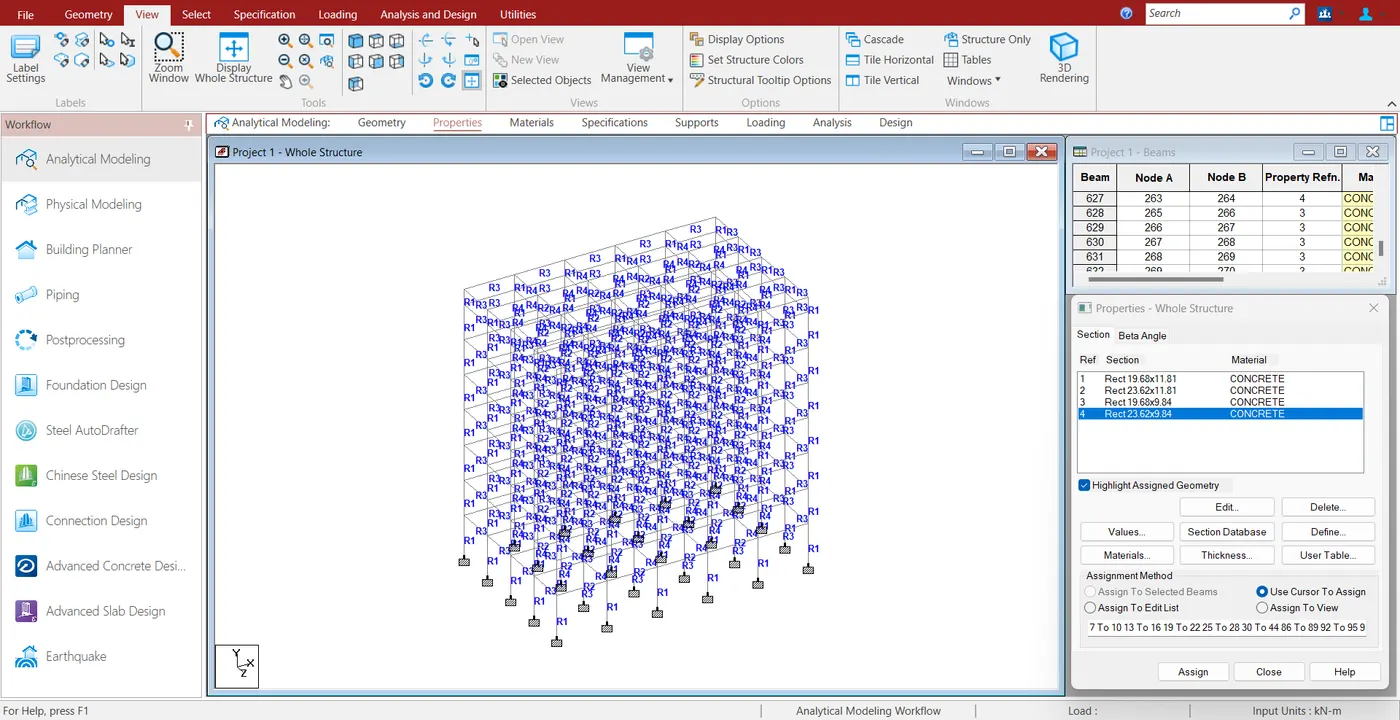
Beam size is taken as follows;
| Element | B (mm) | D (mm) |
| Beam - Exterior | 250 | 500 |
| Beam - Interior | 250 | 600 |
| Column - Exterior | 300 | 500 |
| Column - Interior | 300 | 600 |
| Slab | 150 |
It's assigned to the model from the Properties tab. The material is Concrete.
4. Assigning Loading
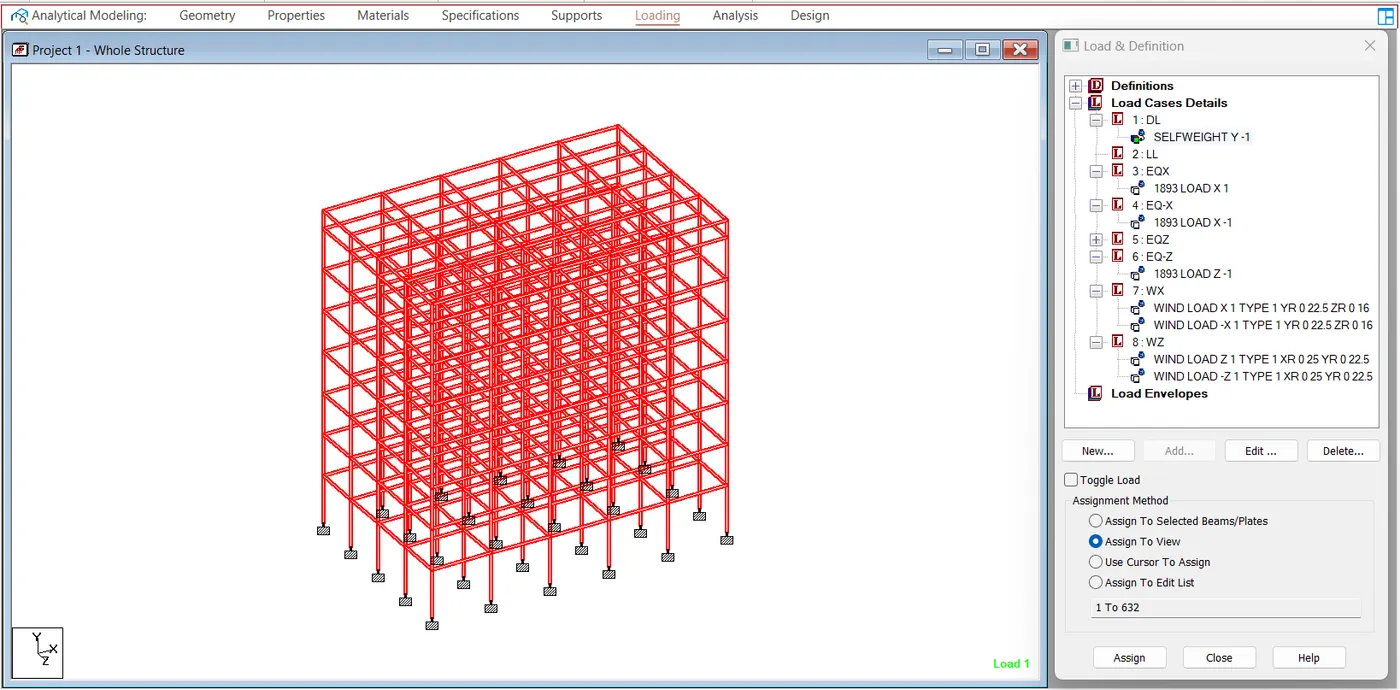
Add Loadcase details as follows.
a) Seismic Load
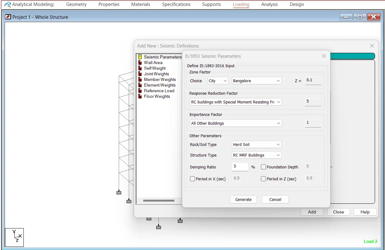
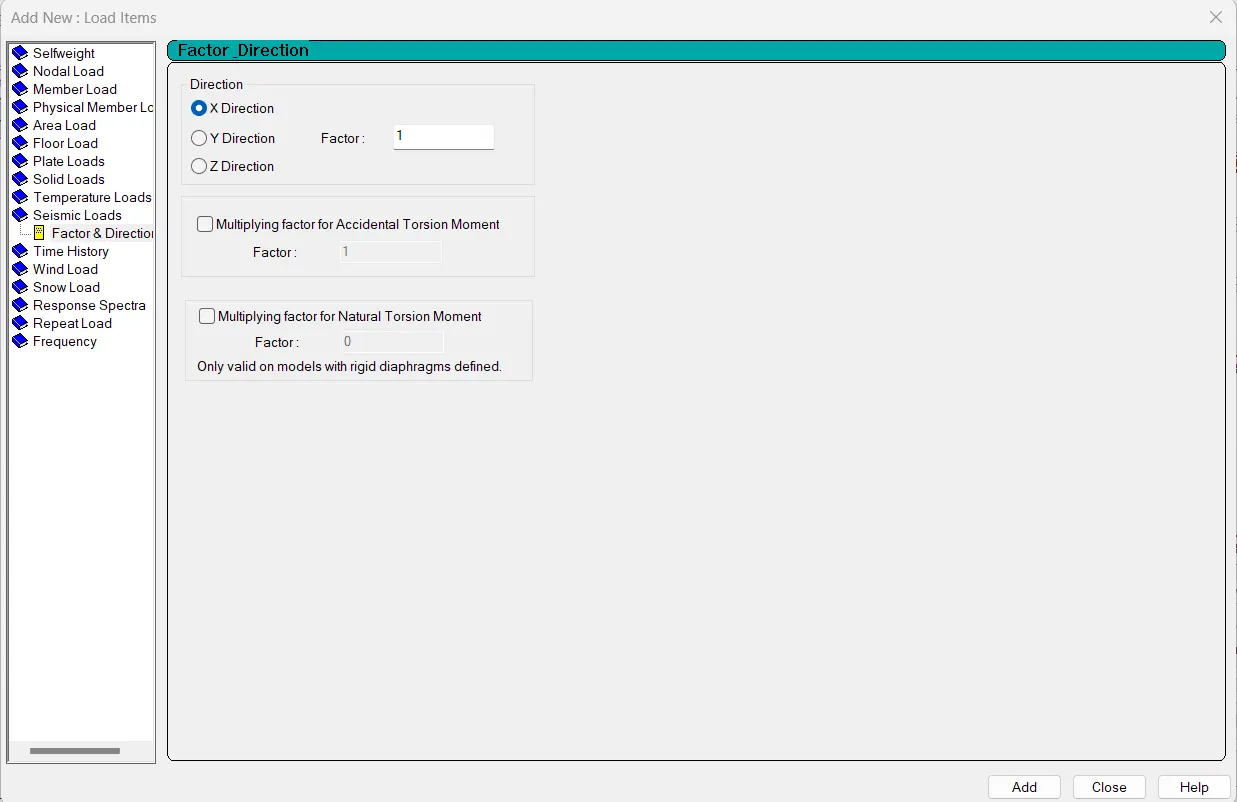
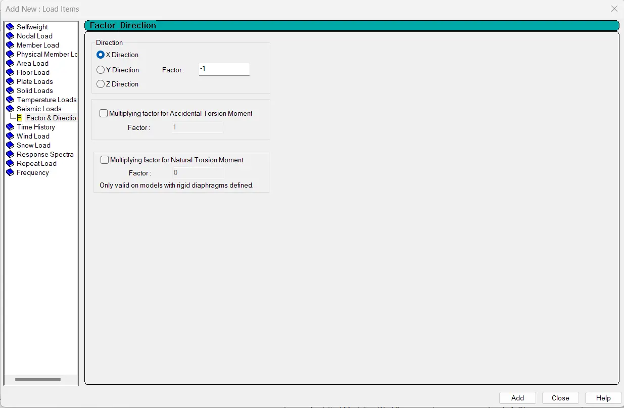
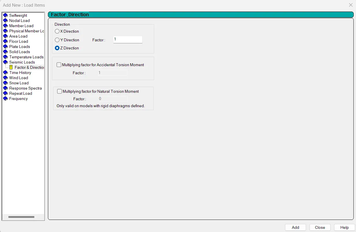
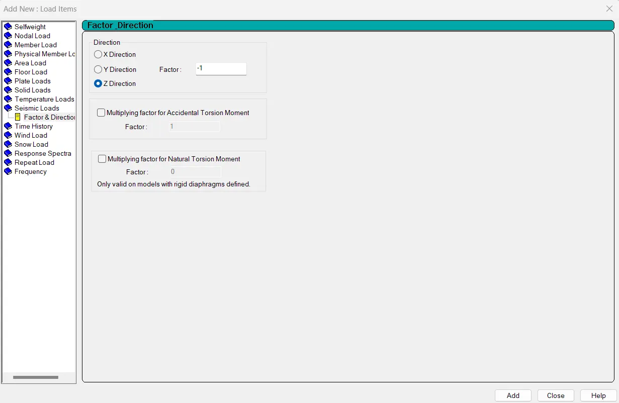
For adding Seismic loads, Seismic Definition is added. IS 1893(Part I):2016 is selected. Earthquake Load in X direction and -ve X direction is added as EQX & EQ-X respectively. Similarly, EQZ and EQ-Z are also added. Calculations are done with the help of Excel sheet.
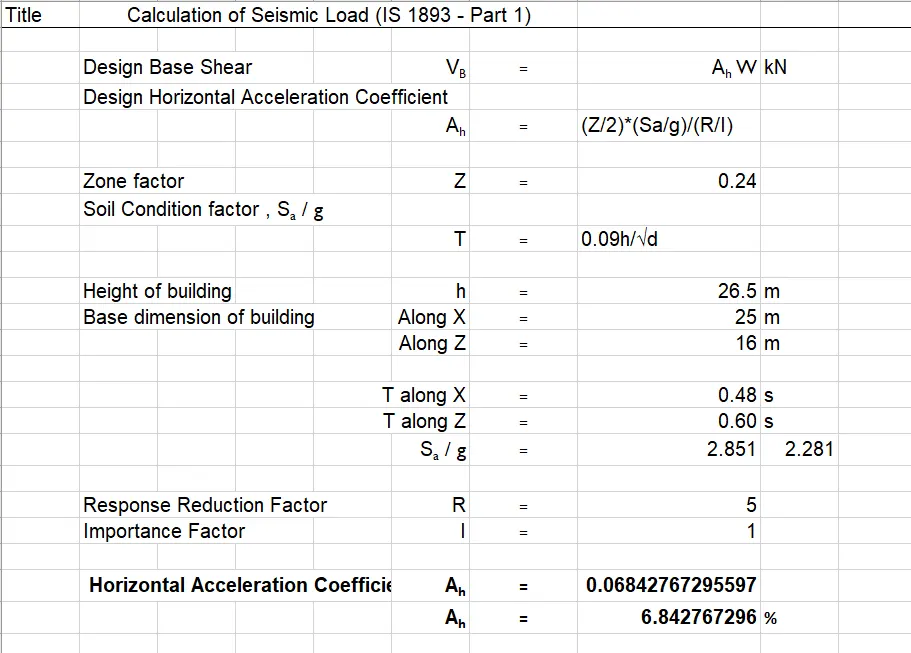
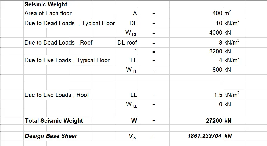
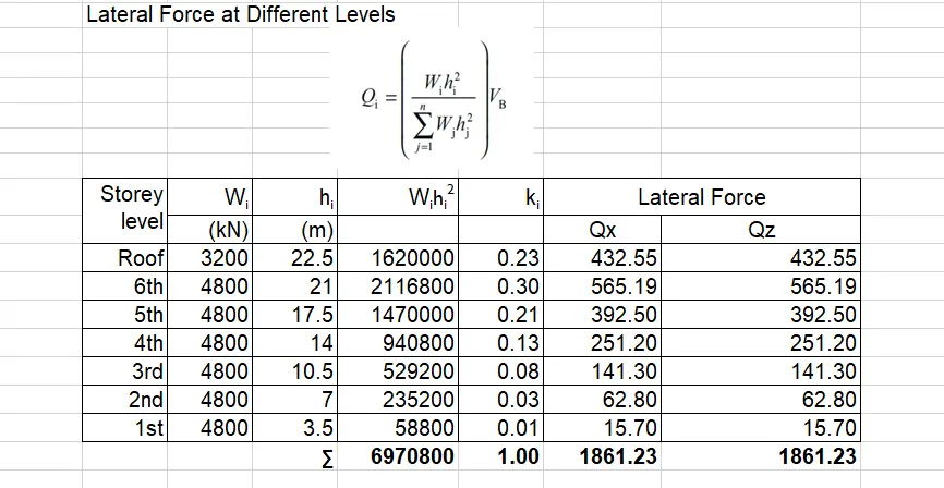
As per the calculations, floor weights are applied in the model.
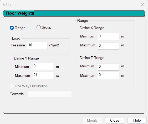
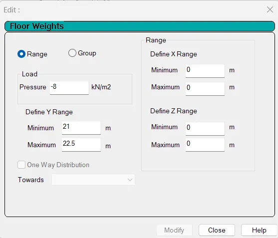
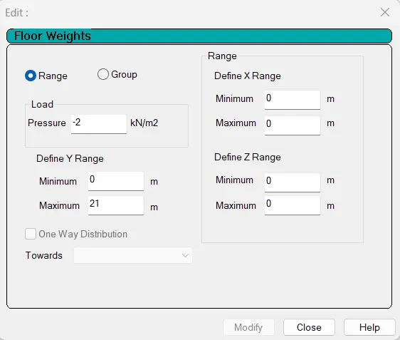
EQX, EQ-X, EQZ & EQ-Z are defined as follows.
b) Wind Load
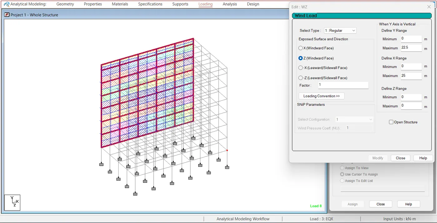
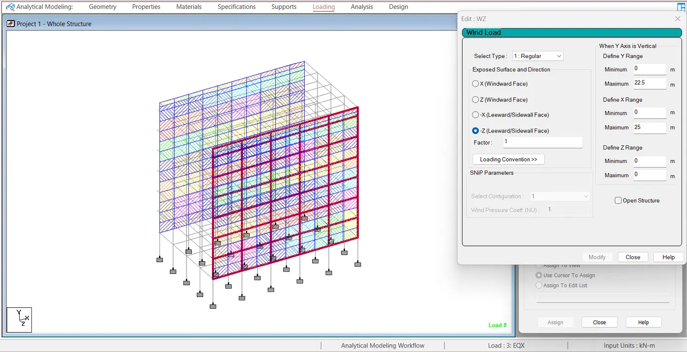
For adding Wind load, Wind Load Definition is added. As per the IS Code, Wind definition details are added.
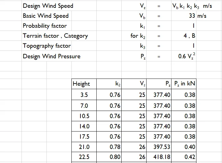
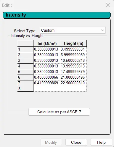
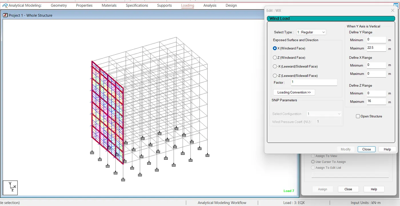
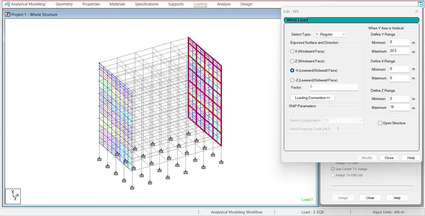
Load case WX is created and wind load in X and -X directions are added as follows.
Load case WZ is created and wind load in Z and -Z directions are added as follows.
c) Dead Load
Load case DL is added.
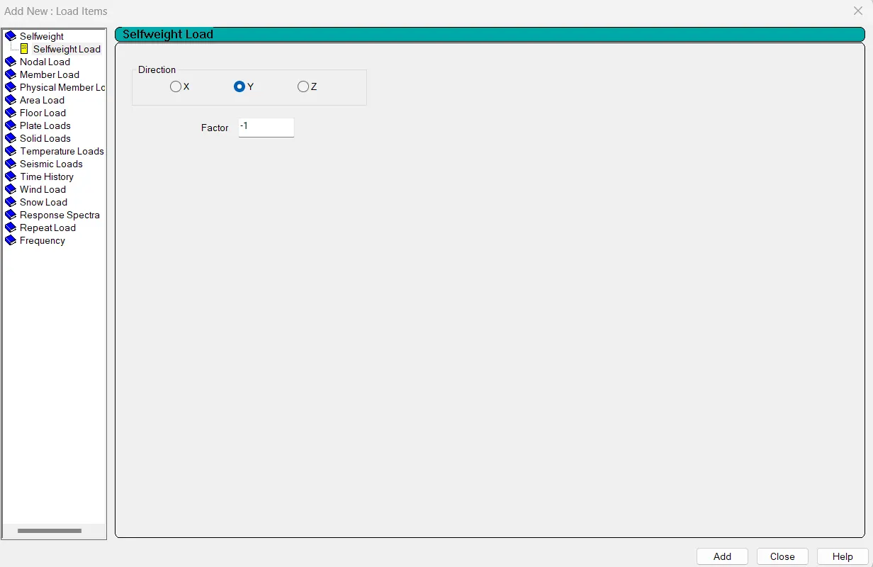
i) Self weight is added and assigned into model.
ii) Floor load is added and assigned into model.
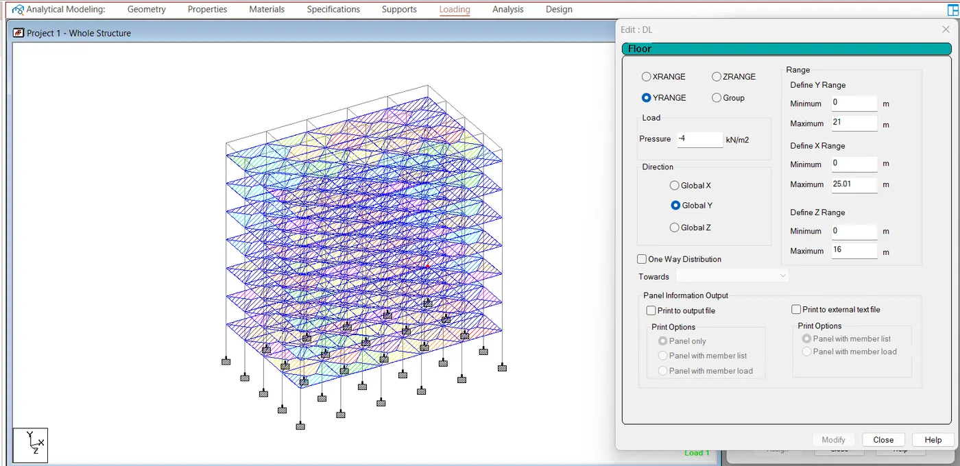
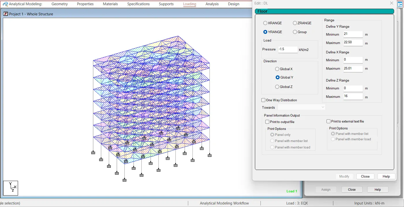
iii) Roof load is added and assigned into model.
d) Live Load
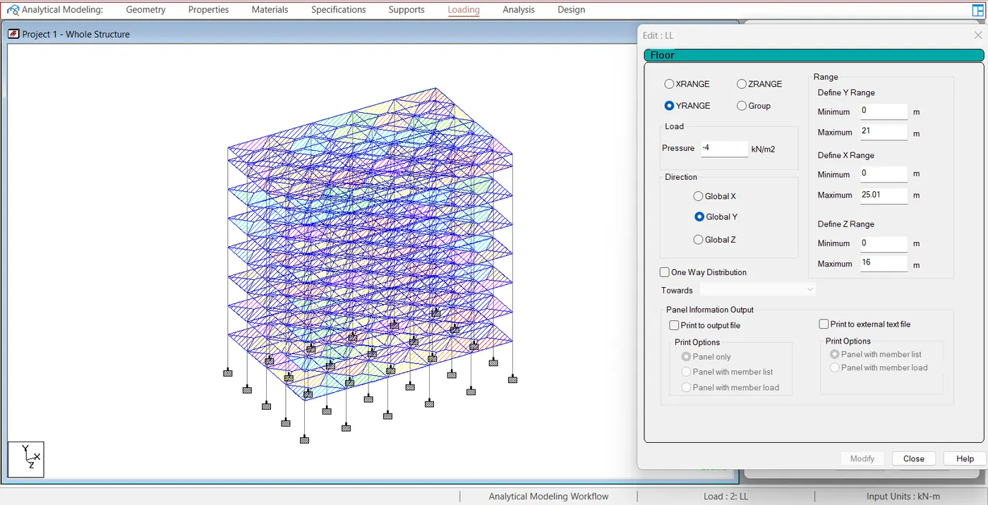
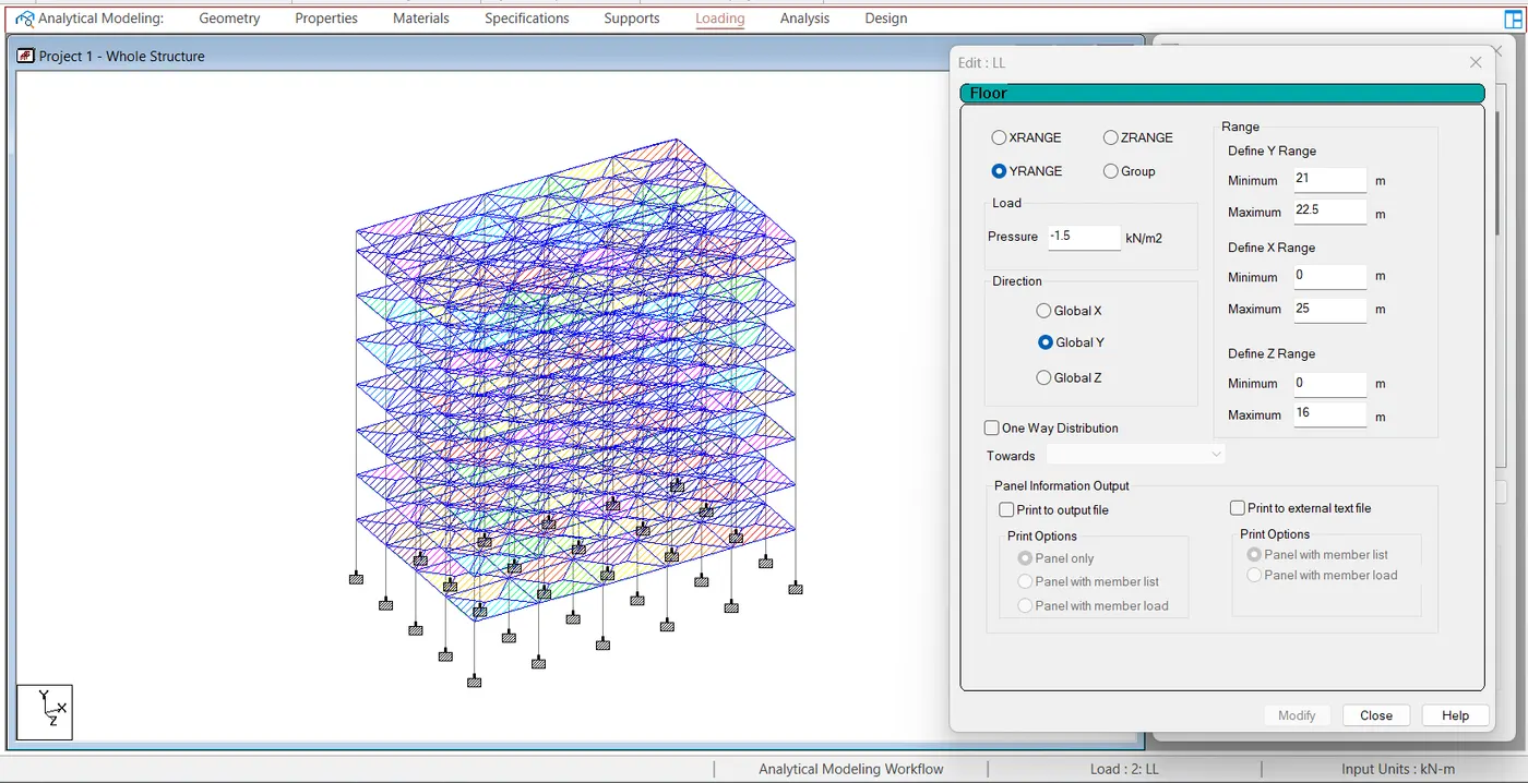
LL of Floor and Roof loads are added.
Load combinations
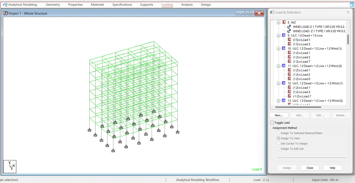
Load combinations are Auto generated as per IS 456:2000, Table 18.
5. Analysis
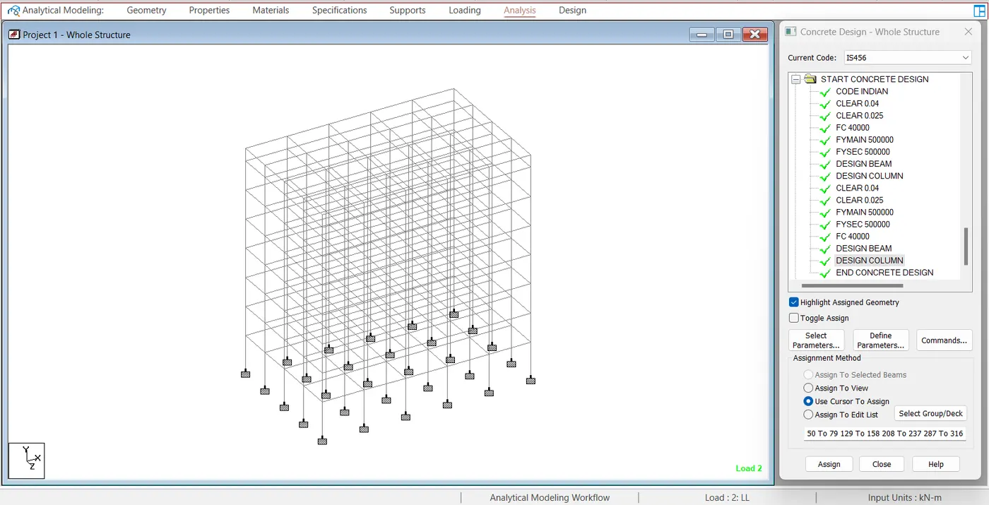
In Analysis, Concrete is selected as material and IS 456 is selected. Parameters are defined as follows.
- CLEAR = 0.04m for Columns and 0.025m for Beams.
- FC = 40,000 kN/m2
- FYMAIN = 5,00,000 kN/m2
- FYSEC = 5,00,000 kN/m2
DESIGN BEAM & DESIGN COLUMN commands are added.
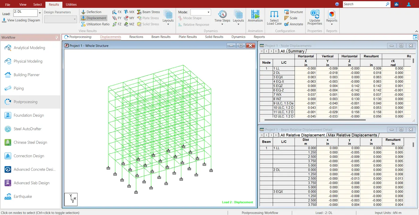
Then Analysis is done.
6. Design with RCDC
For further design, STAAD RCDC is used.
Beams
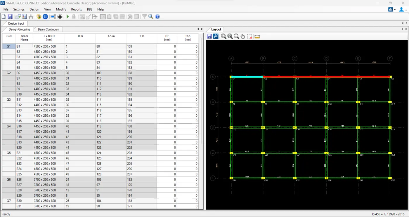
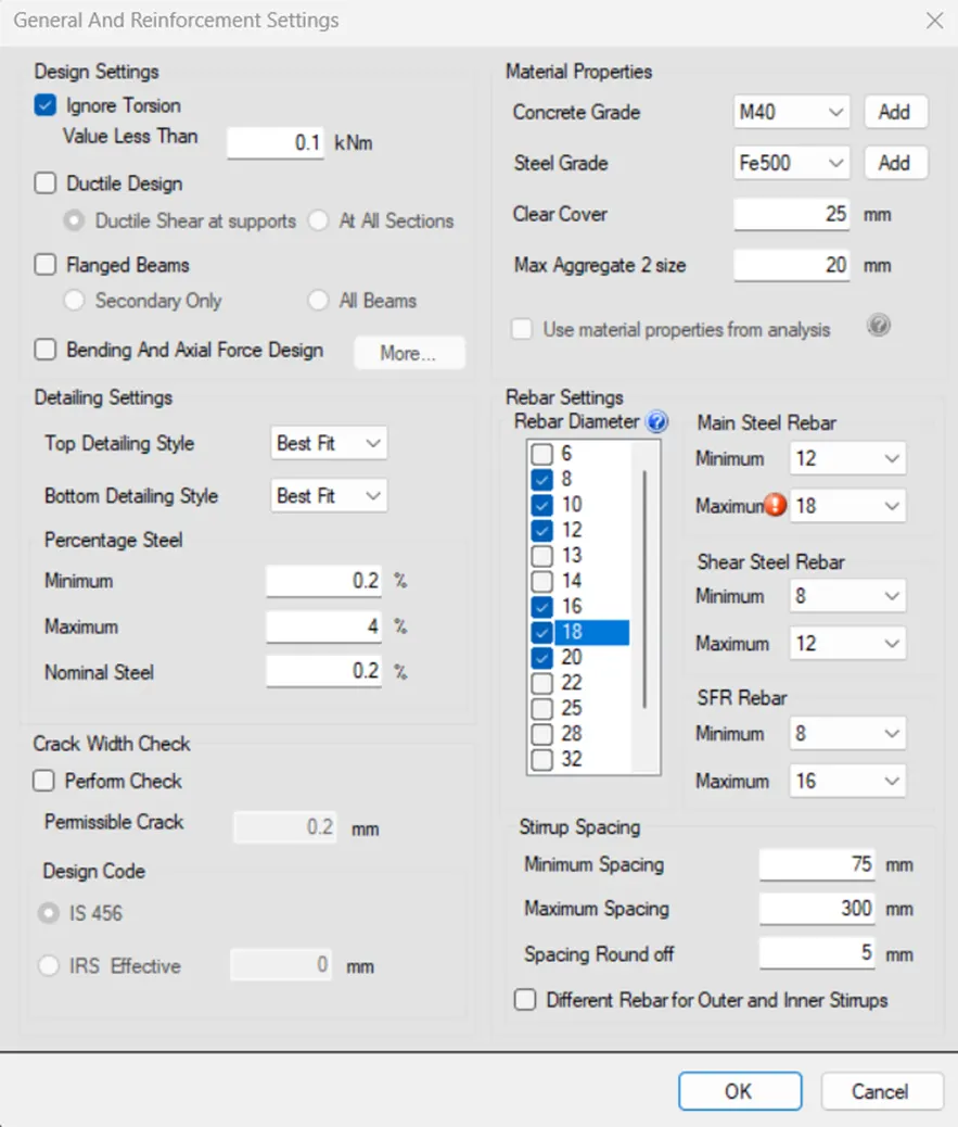
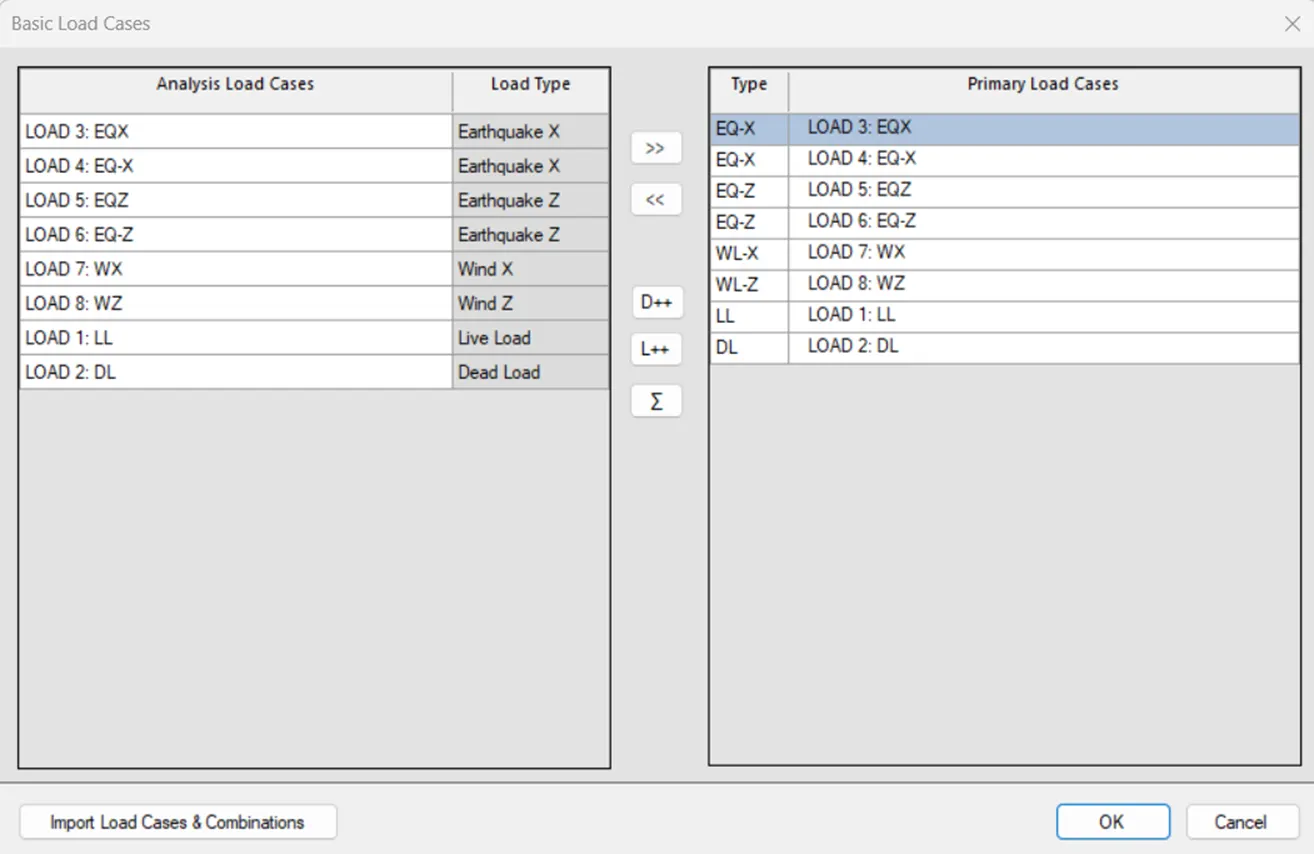
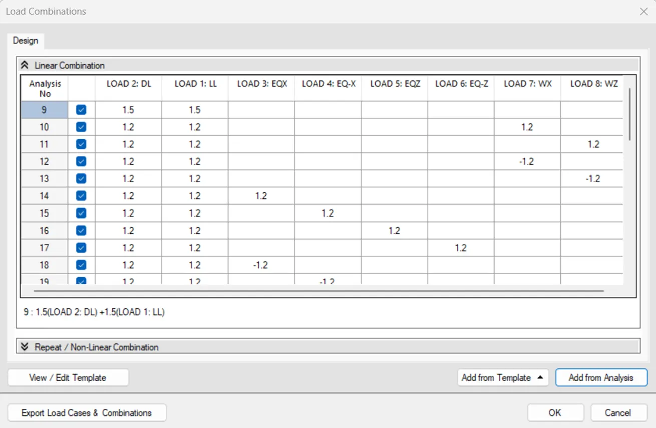
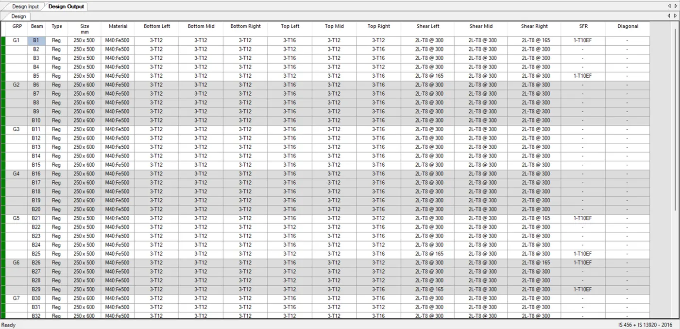
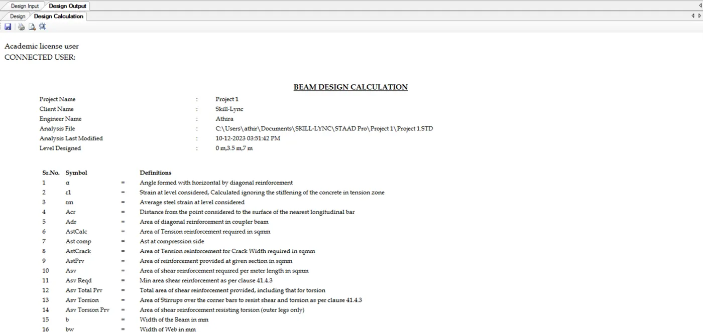
Design calculations of beams are taken.
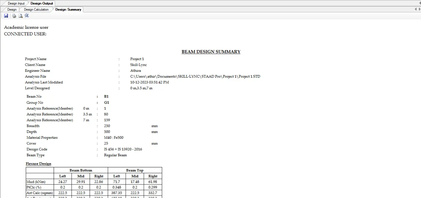
Design Summary is taken.
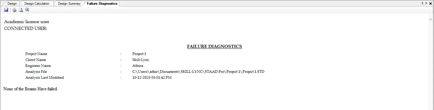
Failure Diagnostics is done.
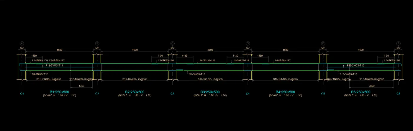
Bar Bending Schedule is taken.
Columns
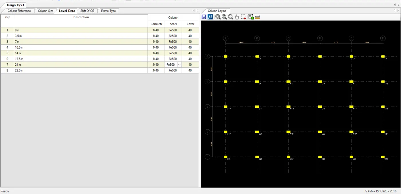
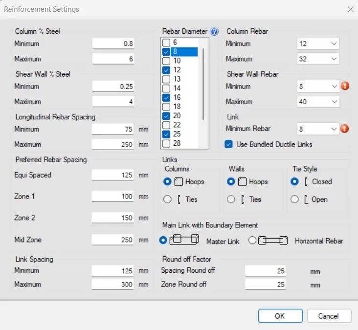
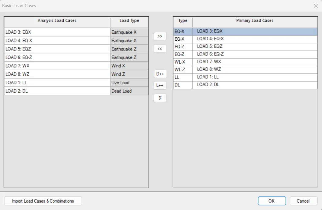
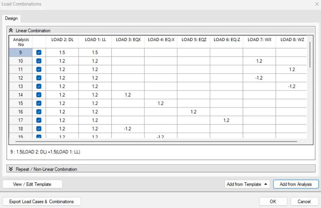
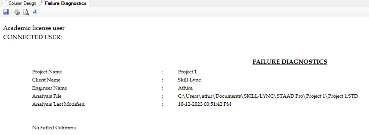
Failure Diagnostics is done.
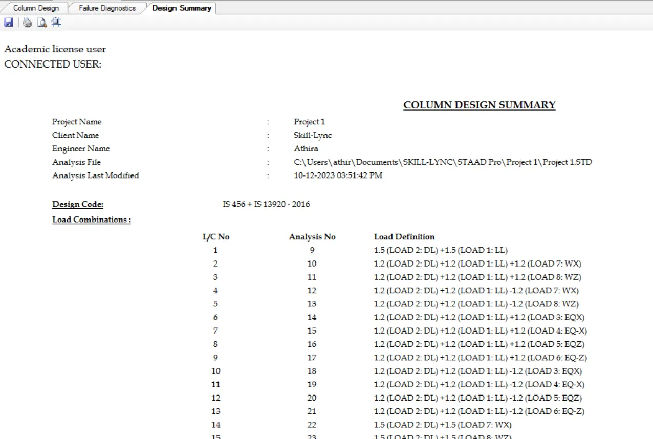
Design Summary is taken.
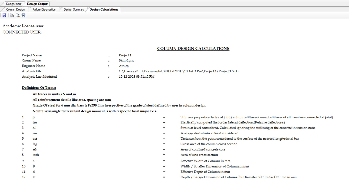
Design Calculations is taken.
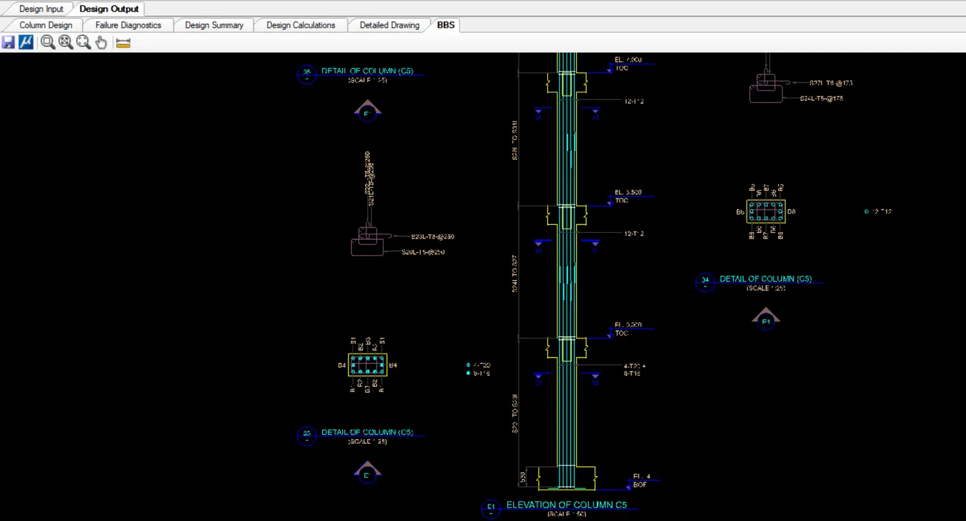
Detailed Drawings of the columns is taken.
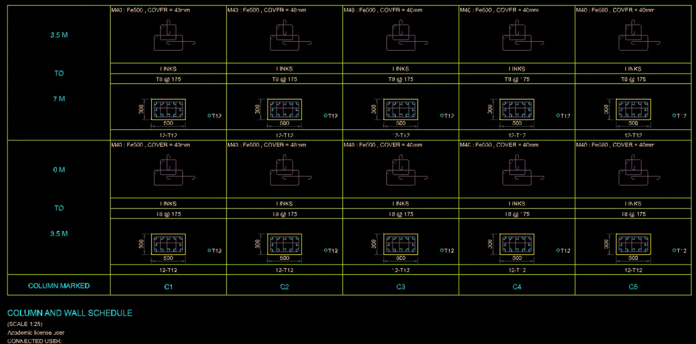
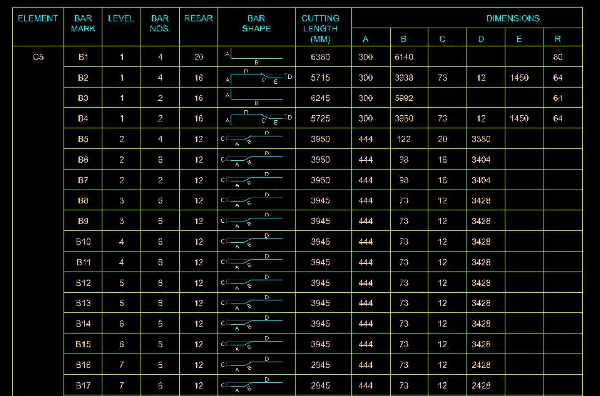
Bar Bending Schedule is taken.
Footing
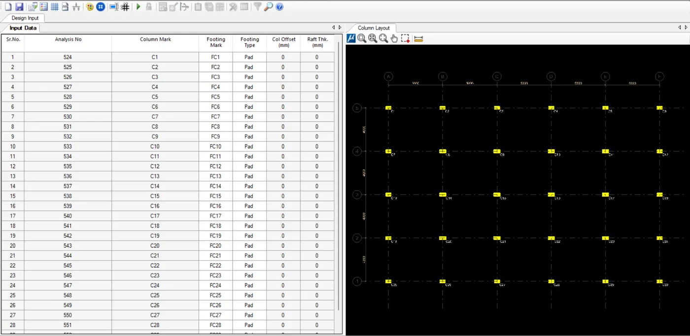
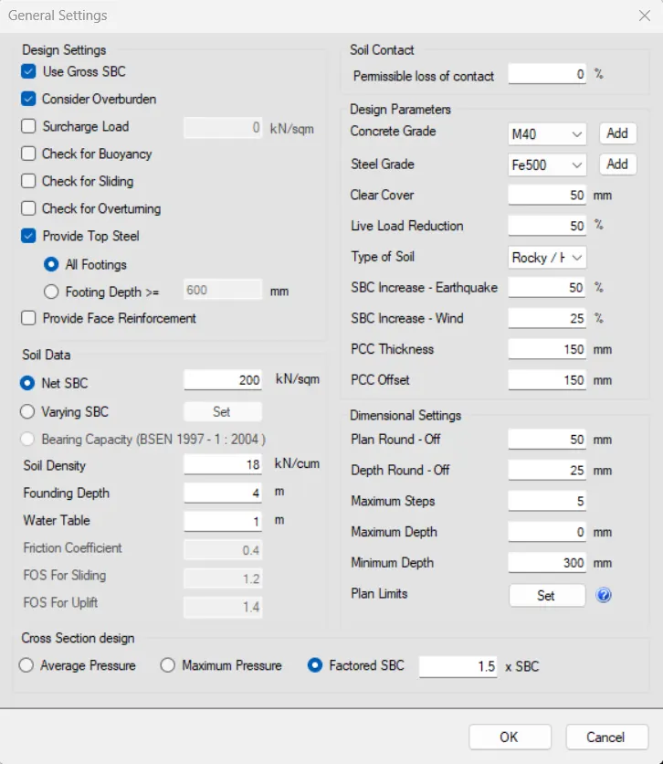
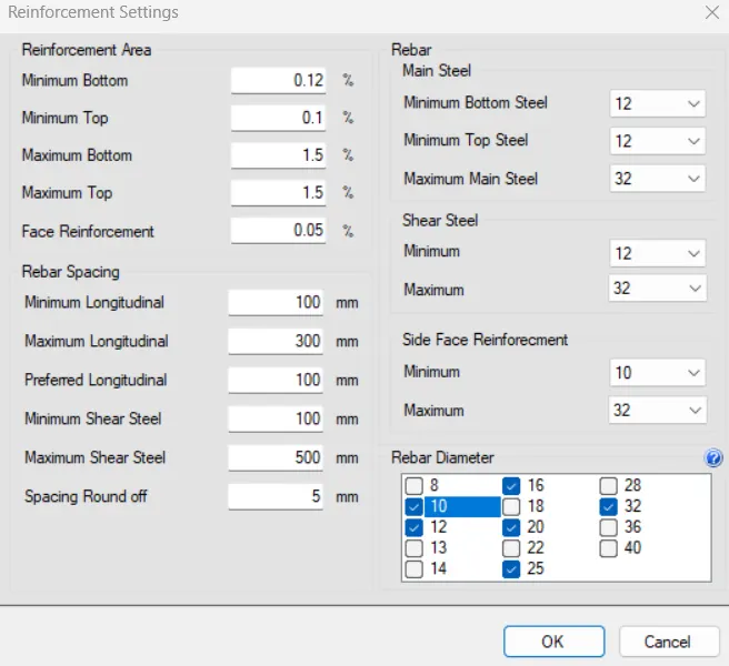
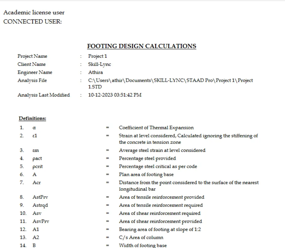
Design Calculation is taken.
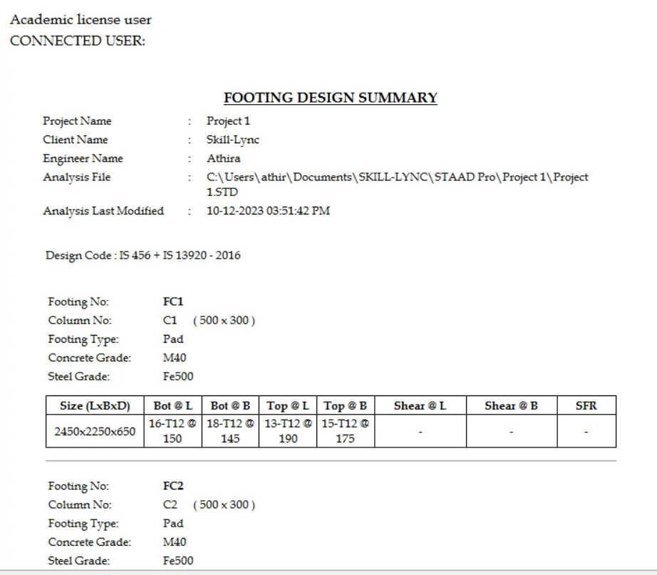
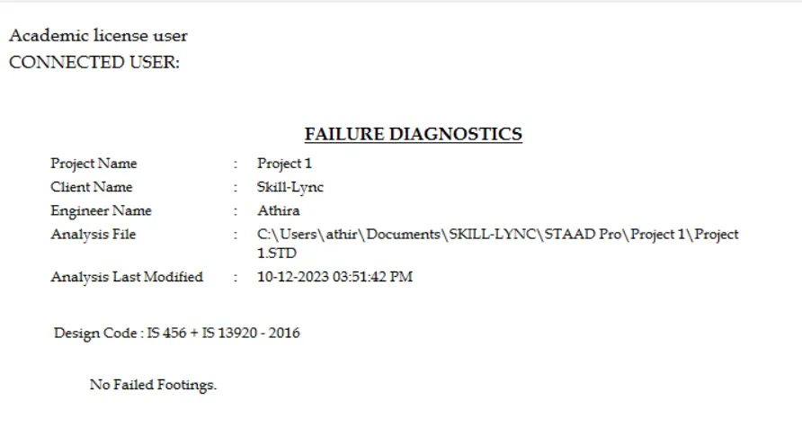
Design Summary and Failure Diagnostics are taken.
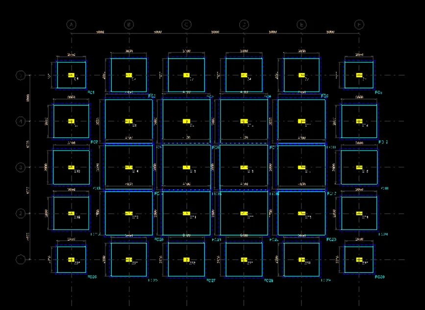
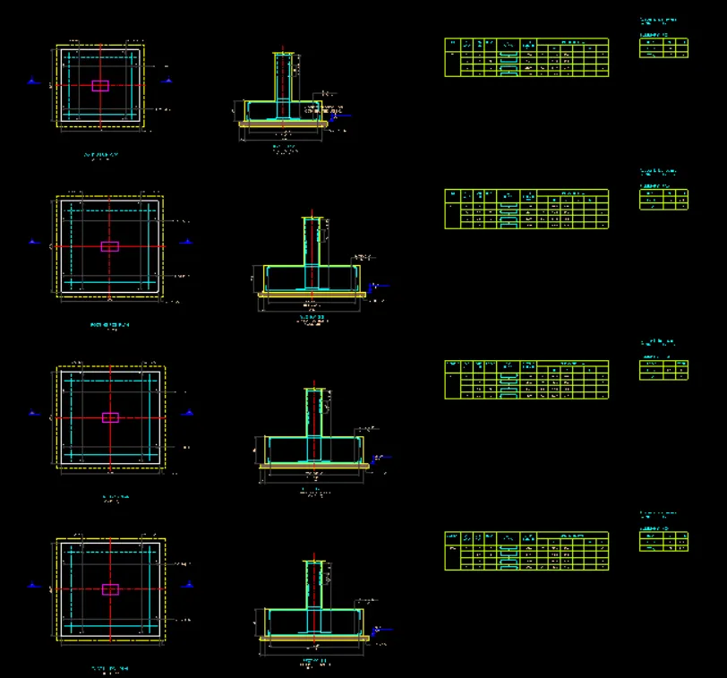
Detailed Drawings are taken.
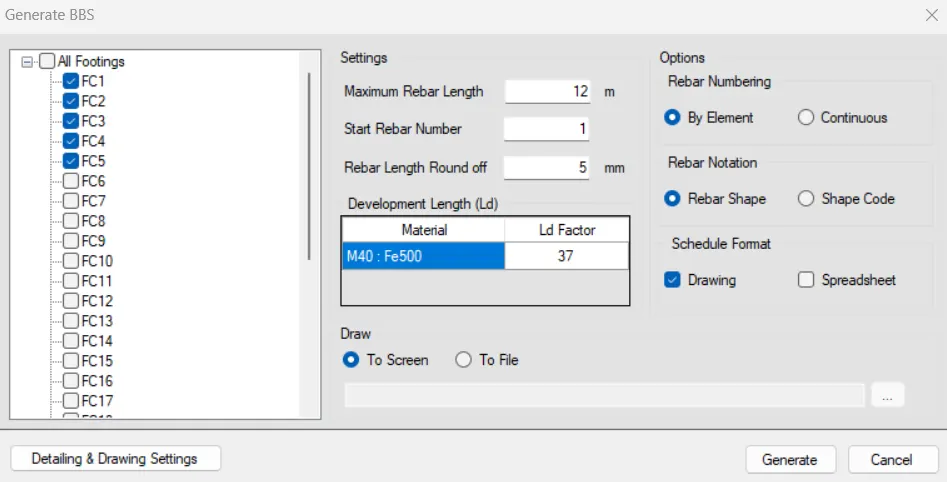
BBS is generated.
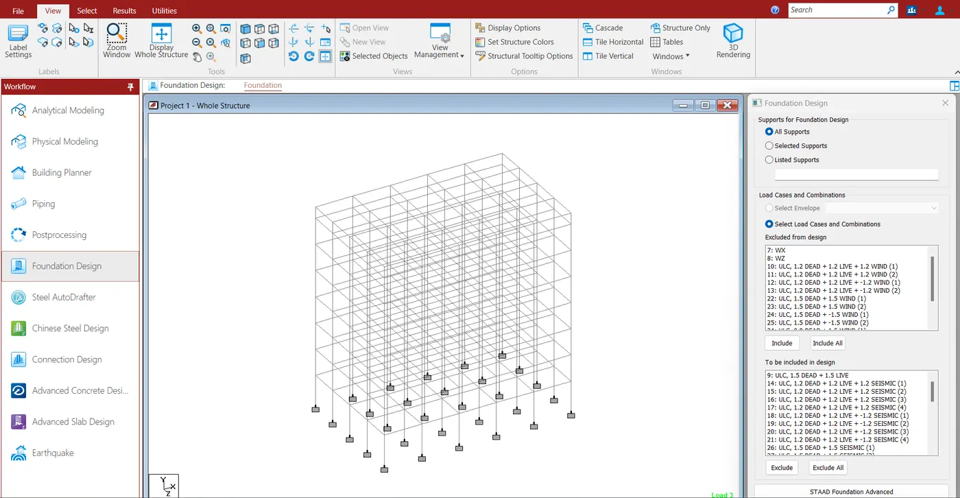
Foundation Design with STAAD Foundation
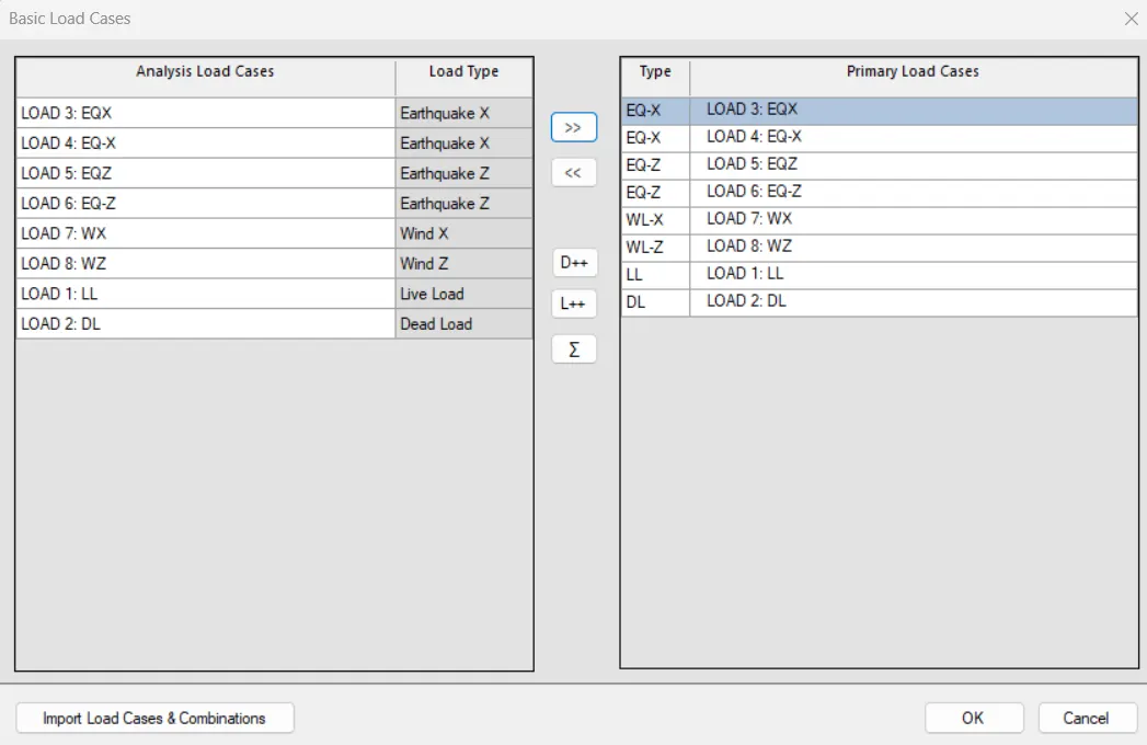
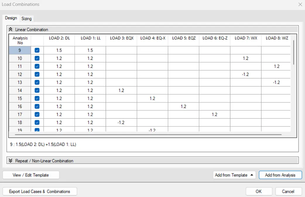
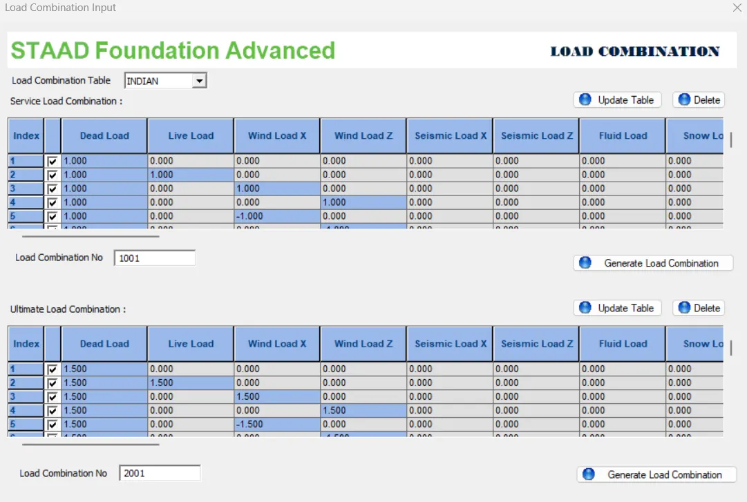
All Seismic loads and combinations and Ultimate load combinations are added to the design.
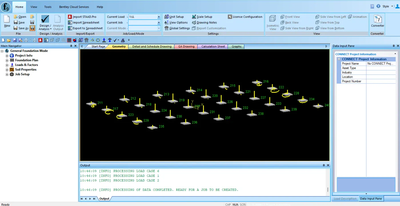
Load combinations are generated.
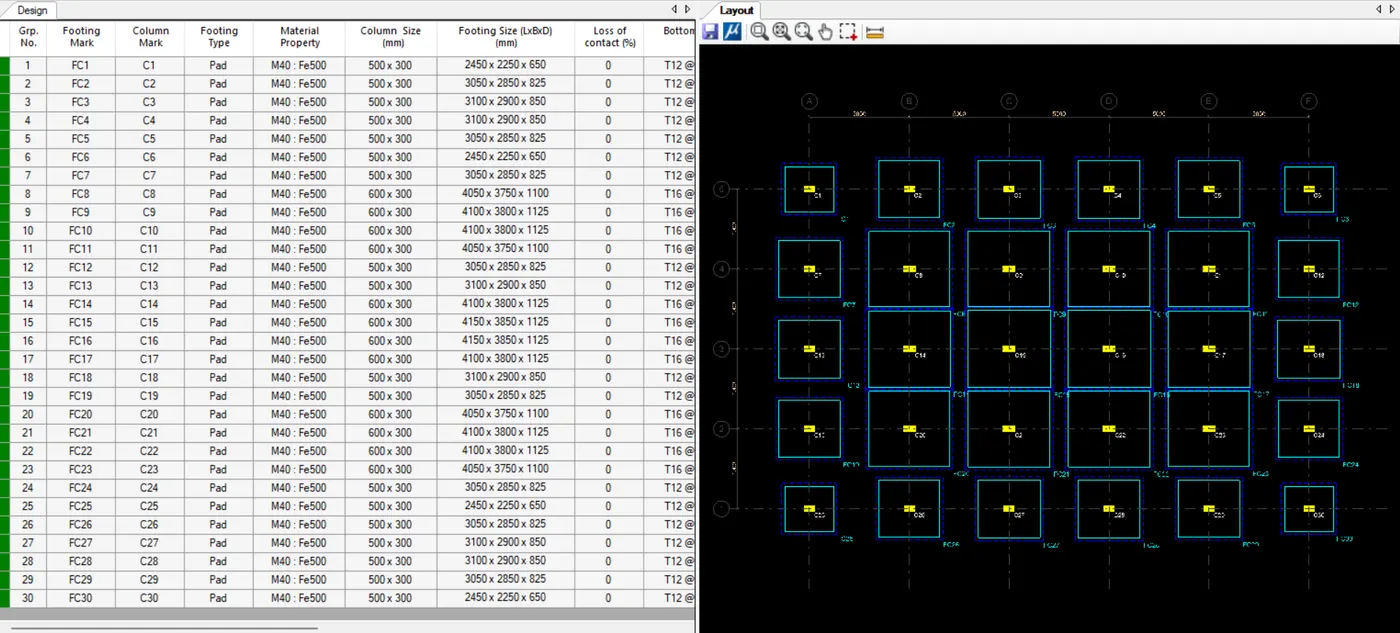
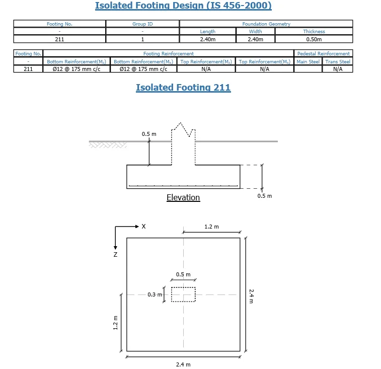
Footing Design is done.
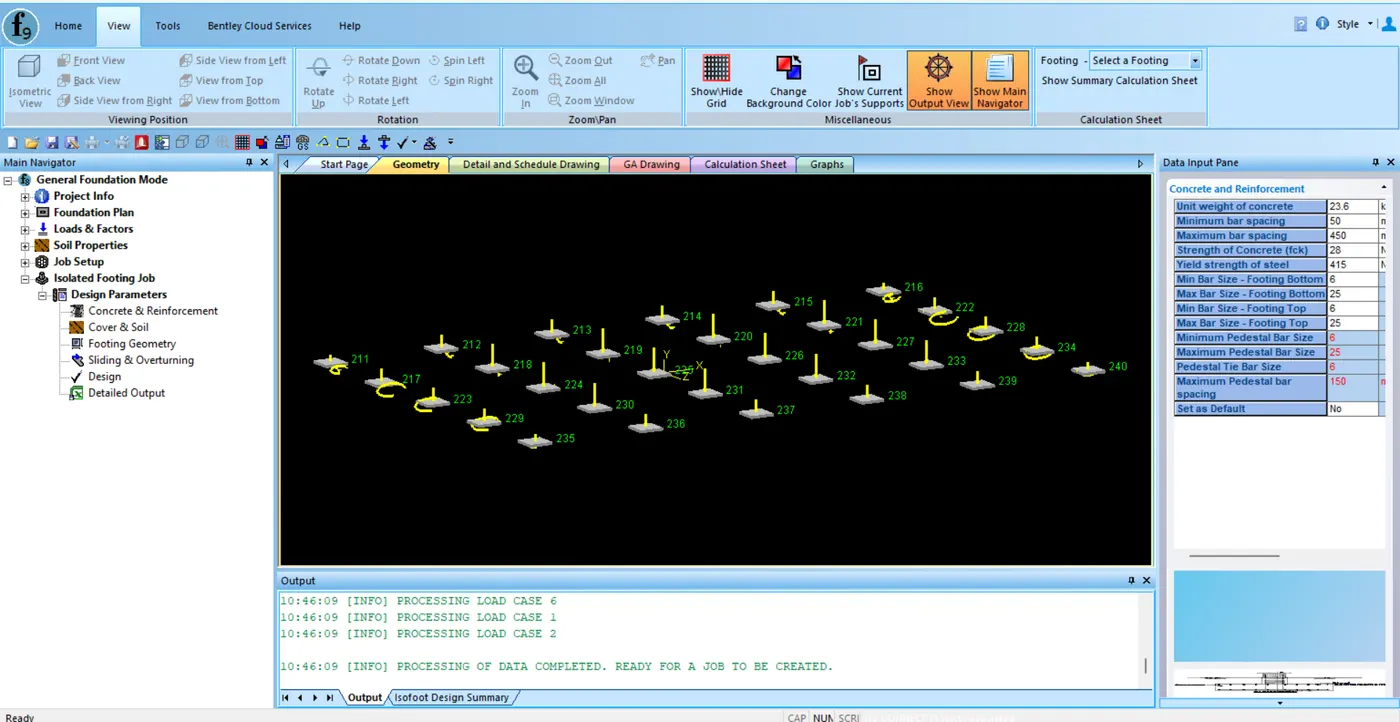
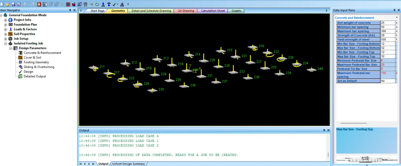
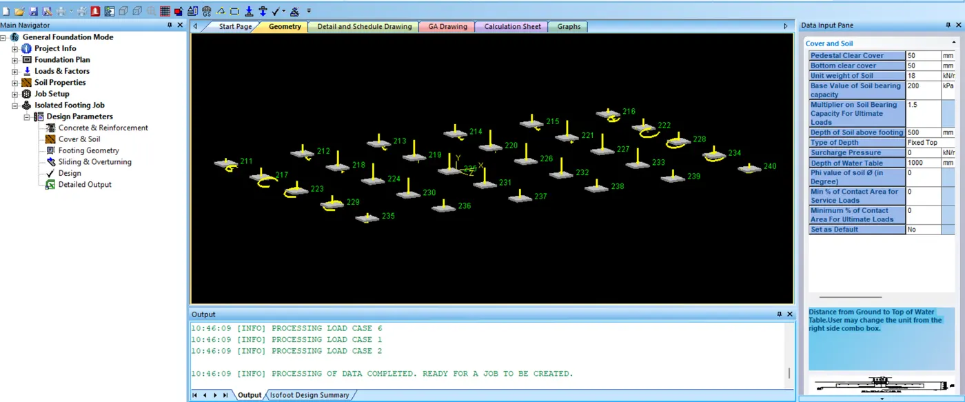
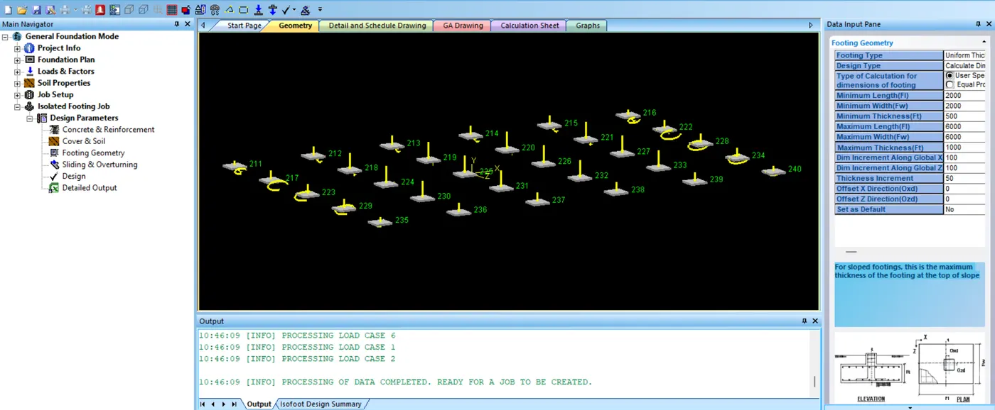
Designing is done and Calculation sheet is taken.
RESULT
The design of G+6+R building has been completed successfully in STAAD Pro Connect Edition according to the IS 456, IS 1893, IS 875 Part 1, 2 & 3.