Project 1
1. Design a multi-storey Residential Building located in Bangalore using STAAD Pro Connect Edition. The specification must be as follows:
|
Building floors |
G + 6 + R |
|
Plan dimension |
B = 25m , L = 16m |
|
Storey Height |
h = 3.5m |
|
Soil |
Hard soil |
|
Use |
Residential Purpose |
|
Safe Bearing Capacity |
180 kN/m2 |
|
Maximum slab thickness |
150mm |
Assume suitable sections for structural elements. Follow IS456, IS1893 and IS 875
- Prepare a Design Basis Report for the project
- Create structural model using STAAD Pro Connect Edition
- Prepare DL, LL, WL and EQL load calculations as per IS 875 standards
- Design slab element using MS – Excel
- Design beam and column element using STAAD RCDC. Attach the design calculation report.
- Design Foundations using STAAD Foundation.
- Prepare bar bending schedule for beam and column using STAAD RCDC
- Attach necessary sketches and drawings wherever required.
- All stipulations, assumptions and design parameter must adhere to Indian Standards.
INTRODUCTION:- In this project I will design a multi-storey residential building (G+6+R), where plan dimension is 25m in width and 16m in length, storey height is 3.5m and I have assumed ground floor height as 4m from foundation level and mumty level height is 2.5m. Beside this, the soil type is hard soil and safe bearing capacity of soil is 180 KN/m2. I have considered slab thickness as 150mm. Moreover, I have used serveral Indian codal provision like- IS-456, SP-34, IS-1893, IS-875 etc while executing the design.
AIM:- To Design a multi-storey Residential Building (G+6+R) located in Darjeeling using STAAD Pro Connect Edition. Then prepare detailed reports of that project
TOOL AND COMMAND:
- Geometry
- Property
- Loading
- Supprots
- Analysis
- Design
- Run analysis
- Analysis command
- Command file
- Annotate
- Displacement,Fy,Mz
PROCEDURE:-
1) Prepare DL, LL, WL and EQL load calculations as per IS 875 standards
a) Calculation of Dead Load - IS 875 part 1
i)Dead load on Floor
Dead load due to slab = 0.150 x 25
= 3.750 KN/m^2
Partitions = 1.5 KN/m^2
Floor Finish = 2.5 KN/m^2
Miscellaneous = 1 KN/m^2
Total Floor Load = 8.75 KN/m^2
I will consider floor load as 10 KN/m^2
ii) Dead load on Roof
Dead load of Roof Slab = 4 KN/m^2
Insulaions and Water Proofing = 0.5 KN/m^2
MEP Services = 0.5 KN/m^2
Miscellaneous = 0.5 KN/m^2
Total Roof Load = 5.5 kN/m^2
I will consider roof dead load as 8 KN/m^2
b) Live Load - IS 875 part 2
i) For Residential Building LL = 4 kN/m^2
ii) For Roof = 1.5 kN/m^2
c) Calculation for EQ Load:-IS 1893 part 1
PROCEDURE:-
Step:1- Calculation of design base shear:
We know that,
VB = Ah x W
Where,
Ah = horizontal seismic coefficient (cl. 6.4.2 of IS1893 – 2016)
W = Total seismic weight of the structure. (cl. 7.4 of IS1893 – 2016)
A) calculate design horizontal seismic coefficient, Ah, which is given by (cl. 6.4.2 of IS1893 – 2016):

Where,
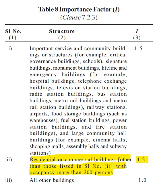
I = Importance factor of the structure depending on the function or use. This factor can be obtained from table 8 of the code (cl. 7.2.3 of IS1893 – 2016).
Z = seismic zone factor given in Table 3;
R = Response reduction factor. This value is obtained from table 9 of the code. (cl. 7.2.6 of IS1893 – 2016)The value of 1/R shall not be more than one.
Sa/g = average response acceleration coefficient. This value depends on time period of structure and on soil type. This can be obtained from clause 6.4.5 of the code.
Sa = Soil condition, It is always better to refer geotechnical report to consider this in our calculation
Time period,Ta = 0.09h/sqrt. d
Since, d = best dimension of building at plinth level along the consider direction of earthquake shaking
h = height of building 7.6.2 in m
Now,
I = Importance factor of the structure from table no 8
I = 1.2
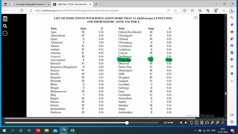
Z = seismic zone factor given in Table 3; or from ANNEX - E list of city factor from page no 36
.'. Z= 0.24
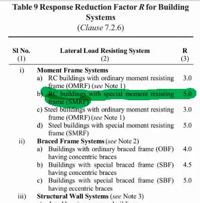
R = Response reduction factor. This value is obtained from table 9 of the code. (cl. 7.2.6 of IS1893 – 2016)
R= 5 (Used condition:RC building with special moment resisting frame i.e SMRF )
Time period, Ta = 0.09h/sqrt. d
Given data,
* Height of building, H= 27m
* Dx, along X = 16
* Dz, Along Z = 25
Tx = 0.09h/sqrt. d
= 0.09x 27/ sqrt. 16
Tx along X = 0.61
Tz = 0.09h/sqrt. d
= 0.09x 27 / sqrt. 25
Tx along z = 0.49
Therefore, Time period or periodic oscilation is 0.61
Hence,
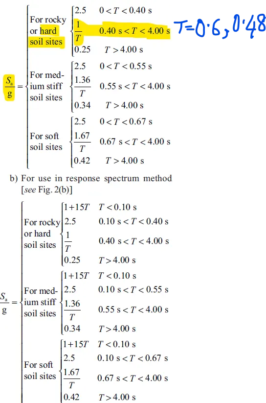
Sa/g = average response acceleration coefficient.
a) For use in equivalent static method
For rocky or hard soil sites, Sa/g = 1.7 = 0< T < 0.40 s
Hence, (Sa/g) along X = 1.677 & Z = 2.096
.'. Horizontal acceleration coefficient (Ah)
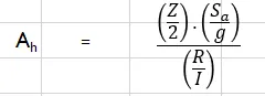
From that above equation value of Ah = 0.048096 = 4.81%
B) calculate Seismic weight,
- Now assume No of floors = 7 i.e G+6
- Hence Height of floor is 3.1 m
- Roof Height = 27 m from GL
- Area of each floor = 16x25
A = 400m^2
- Due to dead load , Typical floor , DL= 10KN/M^3
Wfdl = 400x10 KN
Wfdl = 4000 KN
- Due to dead load, Roof , DL= 8KN/M^2
Wrdl = 400x8 KN
Wrdl = 3200 kN
- Due to live load , Typical floor , LL = 4KN/M^2
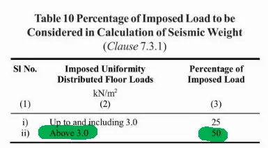
Wfll = 400x4x 0.5 KN
Wfll = 800KN
where 0.5 is from table 10 (Reduce it 50%)
- Due to live load , Roof , LL = 1.5KN/M^2
Wrll = 0KN ( Their is no load on their except only floor finish)
- According to clause 7.3.2 of IS-1893 (2002) live load for roof not to be considered

- Therefore, Live load for Roof = 0 KN/m2
- Total seismic weight = (Total number of floor x Wfdl ) + Wrdl + (Total number of floor x Wfll ) + Wrll
= (7 x 4000 ) + 3200 + (7 x 800) + 0
W= 36800 KN
Therefore, Design Base shear, Vb = Ah x W
= 0.0481 x 36800
Vb = 1770.1 KN
Step:2- Calculation of lateral force at different :
We know that,
used [cl.7.6.3 (a) of IS1893 – 2016]:
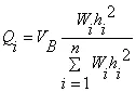
Where,
Qi = design lateral force at floor i ;
Wi= seismic weight of floor i;
hi = height of floor i measured from base; and
n = number of storeys in building, that is, number of levels at which masses are located
Given data,
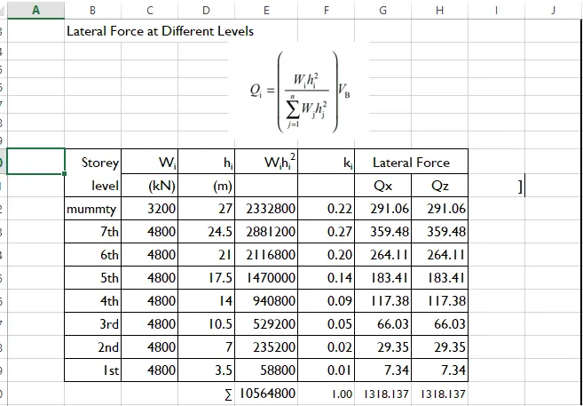
* seismic weight of ground floor Wi = Wfdl + Wfll
= 4000 + 800
Wi = 4800 KN
* Height of floor = hi = 3.1m
* No of floors = 7
* Vb = 1770 KN
- Calculate lateral force at different level by using above formula, By using Excel
c) Calculation for Wind Load:-IS 875 part 3
i) Calculation for Design Wind Speed:-
We know that
Vz = Vb x k1 x k2 x k3 x k4
where ,
Vb=Basic wind speed (m/sec)
K1=Risk coefficient (Table 1 of IS 875 (Part 3)-2015)
K2 = Terrain Roughness and height factor
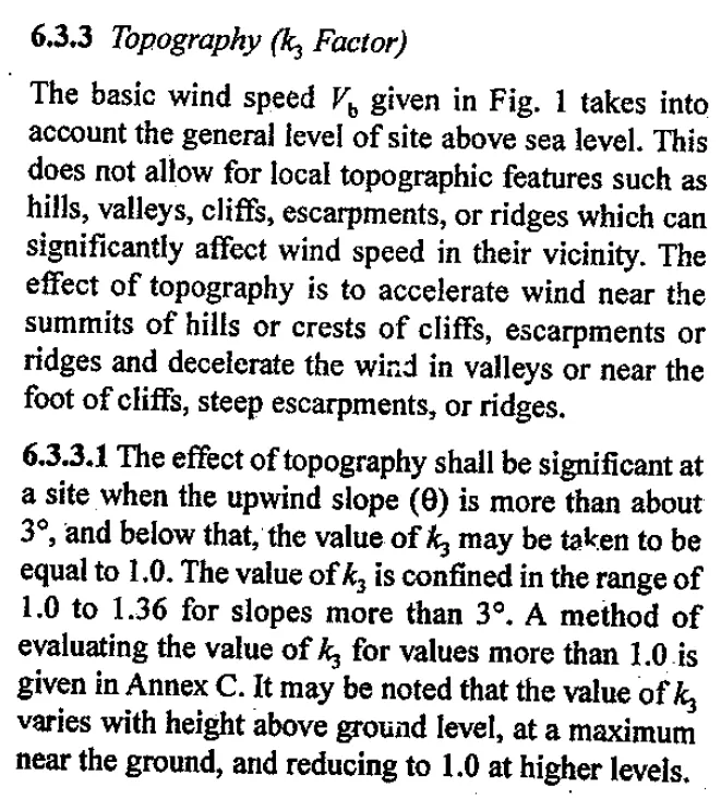
K3=Topography factor (Clause 6.3.3 of IS 875 (Part 3)-2015)
K4 =Importance factor for Cyclic Region
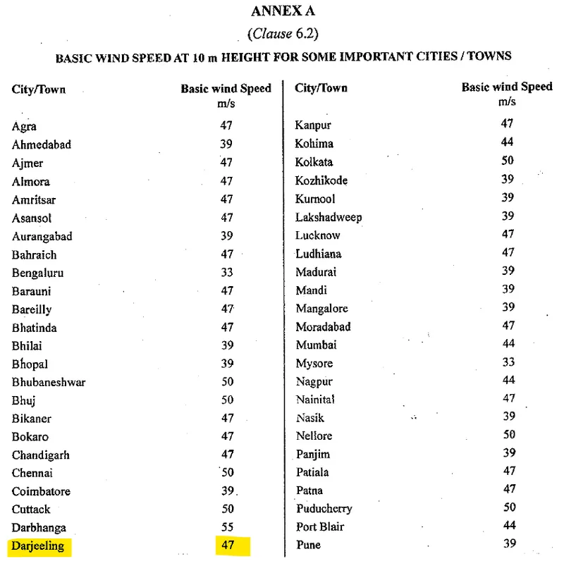
AS Vb = 47 m/s ( Darjeeling ) Is 875 Annexure A
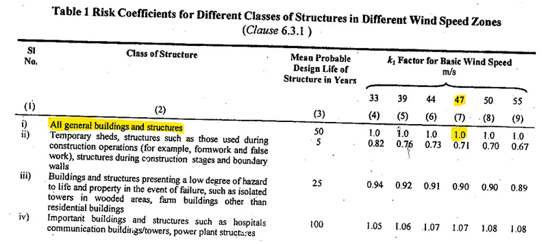
K1 = 1 (given in Table 1 of IS-875 part 3)
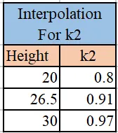
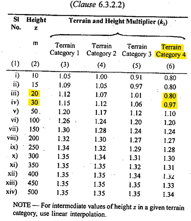
K2 = 0.91 ( Ht for 26.5m) (Category 4 as building is located in city center)
K3 = 1 [Topography factor (Clause 6.3.3 of IS 875 (Part 3)-2015)]
K4 = 1 [Clause 6.3.4 of IS 875 (Part 3)-2015] As this zone does not falls under cyclone zone
Therefore ,
Vz = 47 x 1 x 0.91 x 1 x 1
= 42.77 m/s
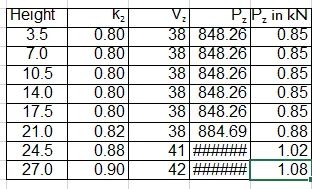
ii) Wind Pressure = Pz
Pz = 0.6 x Vz ^2
= 0.6 x 42.77 x 42.77
= 1097.56 N
= 1.097 Kn
RESULT- I calculate DL, LL, EQL and WL for building
2) Design slab element using MS – Excel
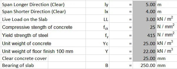
STEP-1:
STEP-2:
According to clause number 24.1 of IS-456 (2000)
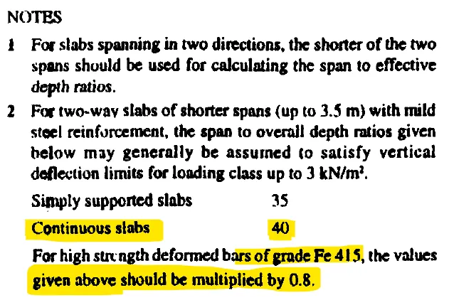
AS per clause 24.2 of IS-456,
- Span to effective depth ratio (l/d) = 0.8 X 40 = 32
- Minimum effective depth (d) = (Ly X1000)/span to effective depth ratio = (4 X 1000)/32 = 125mm
- Dia of bars for shorter direction = 12mm
- Dia of bars for longer direction = 12 mm
- Overall depth = [(Minimum effective depth + clear concrete cover + (Dia of bars for shorter direction/2)]
= [(125 + 25 + (12/2)] = 156 mm
- Provide overall depth = 150mm
- Effective depth = [provided overall depth - clear concrete cover - (Dia of bars in shorter direction/2)]
= [150 - 25 - (12/2)] = 119mm
Loading on Slab:
- Dead load of the slab = (Unit weight of concrete X 1 X 1 X Provided overall depth)/1000
= (25 X 1 X 1 X 150)/1000 =3.75 KN/m2
- Super dead load = 4 KN/m2
- Live load on the slab = 3 KN/m2
- Total load on the slab = (3.75+4+3) = 10.75 KN/m2
- Design Load = (Total Load x Load Factor i.e. 1.5) = (1.5 X 10.75) = 16.13 KN/m2
- Effective span, Ly = Span in longer direction + Effective depth = 5+ 0.119 = 5.12m
Lx = Span in Shorter direction + Effective depth = 4+0.119 = 4.12m
- Ratio, Ly/Lx = (5.12/4.12) =1.243 [ Hence it is a two way slab]
From the Table-26 of IS-456
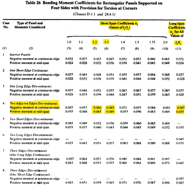
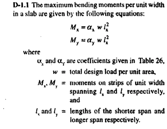
- With the help of Interpolation method we can calculate the value of Alpha-X for 1.243

STEP-3: Calculate BM:

STEP-4: To check the effective depth of slab-

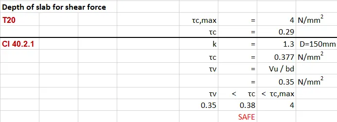
STEP-5: Depth of slab for shear force:-
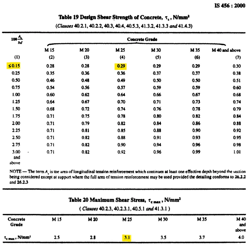
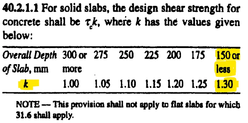
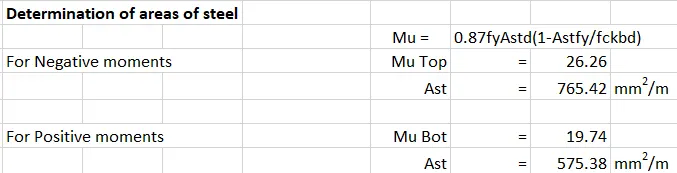
STEP-6: Determination of area of steel:-
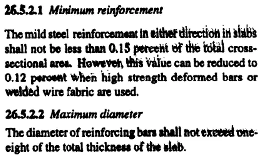
STEP-7: Determination of Distribution steel:-
According to IS-456 (2000) Clause number 26.5.2.1

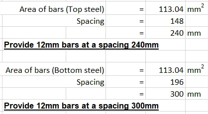
STEP-8: Selection of reinforcement bars:-
3) Create structural model using STAAD Pro Connect Edition:
Step:1 Open Staad pro:
- First open the staad.pro software and fill all the project details and select unit system as Metric.
- Then select the model as analytical.
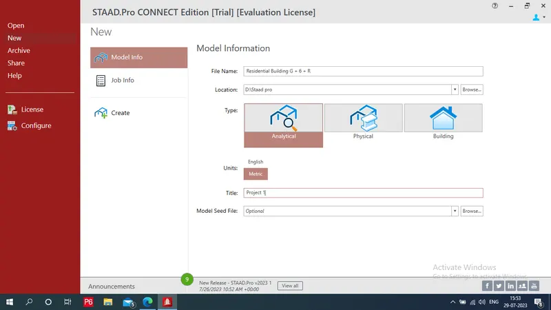
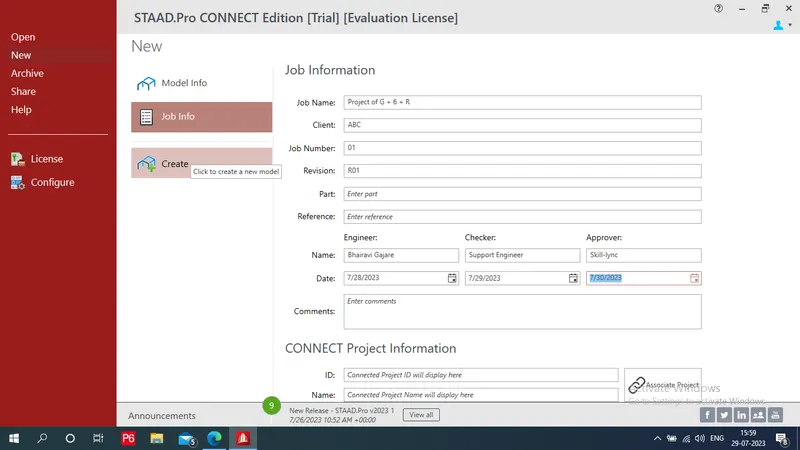
- Provide job information
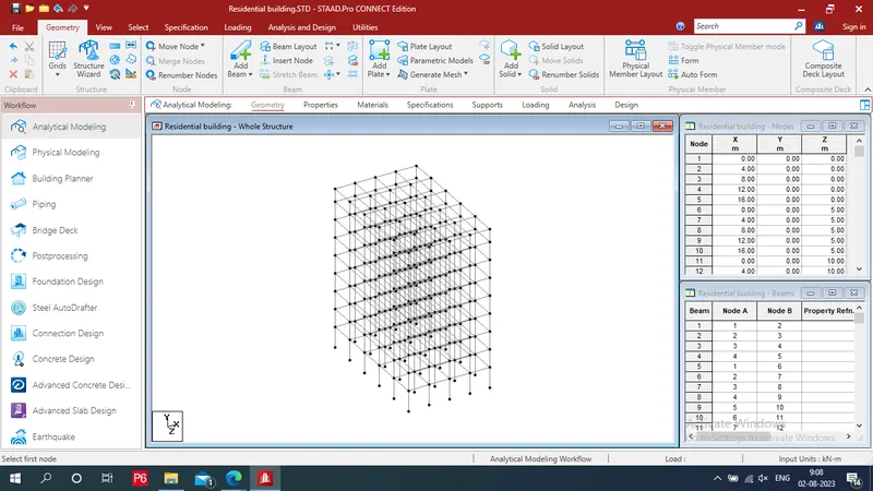
Step 2: To Draw Geometry i.e. To Draw skeletan structure of building:
a) To Draw beams and coloums:
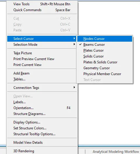
- Right click - select cursor - and choose nodes cursor
- Click on nodes tab in 1,X and put value (0,0,0)
- Select node and click on Trasitional repeat provide global direction:Z - No of steps:5 - Default step spacing:5 - ok
- We get a 6 nodes in Z-direction
- Select add beam from geomerty tab
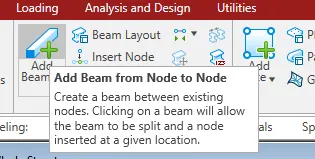
- Join these nodes one by one
- We get a 5 beams
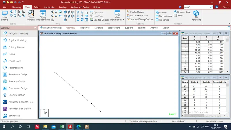
- Again Change cursor type as a node cursor - Then Select all nodes
- click on Translational Repeat commnad from geometry tab in structure section
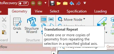
- Provide required data as Gloabal direction: x , step No:4, Default step spacing:4, Check box of Link steps - ok
- We get geometry in X-direction
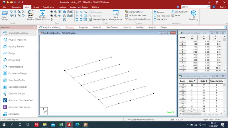
- Repeat this procedure for beams Change cursor type as a beams cursor - Then Select all beams
- Again select Translational Repeat commnad
- Enter required information as Gloabal direction: x , step No:4, Default step spacing:4, Check box of Link steps - ok
- We get closed geometry
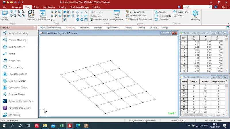
b) To draw nodes for foundation:
- Again Right click - select cursor - and choose nodes cursor
- Select all nodes - Click on Translational Repeat commnad
- Provide Gloabal direction: Y , step No:1, Default step spacing:-4, Check the box of Link steps - ok
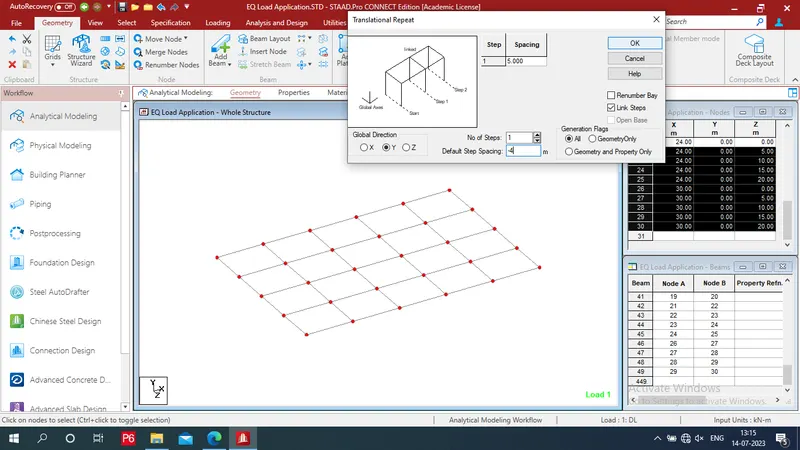
- We get a foundation depth
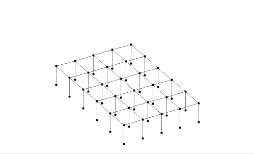
c) To draw nodes for different floors i.e. 1st floor, 2nd floor, 3rd floor, 4th floor, 5th floor, 6th floor , Roof level:
- Change the cursor type i.e. node cursoer
- Go to view tab - select front(5th view) view - Select all nodes
- Click on TR - Gloabal direction: Y - step No:7 - Default step spacing:3.1 - Check the box of Link steps - ok
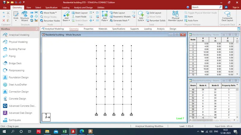
- we get a different floor nodes
d) To draw beams for different floors i.e. 1st floor, 2nd floor, 3rd floor, 4th floor, 5th floor,6th floor, Roof level:
- Repeat this procedure for beam only that cahnge cursor as beam cursor and select beam otherwise reaming process is same
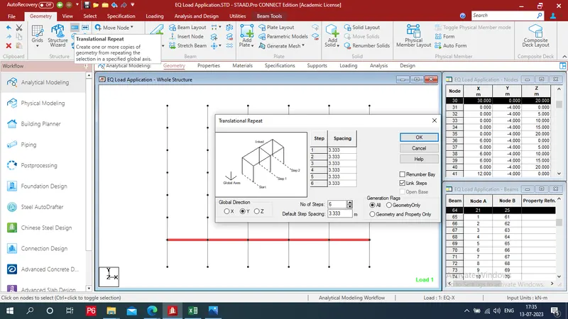
- we get a skeletan structure of hospital building
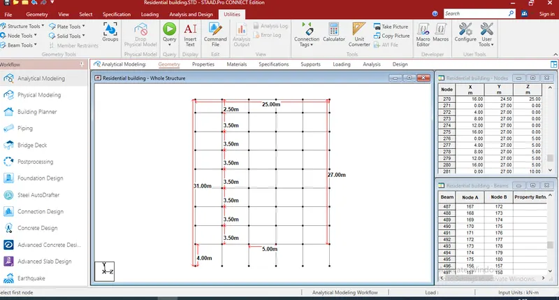
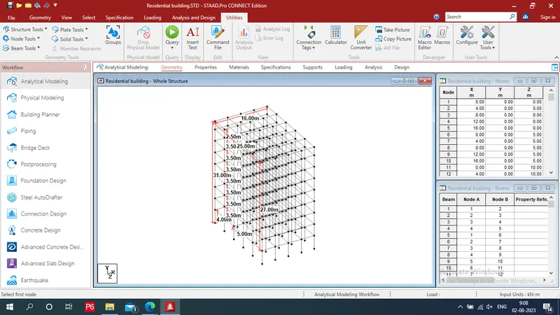
- Then go to view tab make a building front view by using front view option
- Provide anotation node to note from utilitie tab
Step 2: To Apply Properties:
- Click on properties tab which is 2nd stage
- Click on define
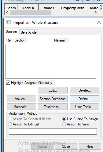
- Select rectangle and provide its depth and breadth my beam size is:
* for beams "300 x 600mm"
* for columns "600 x 800mm"
- Choose material as concrete b/c it is rcc beam - Add it by clicking on add - close tab
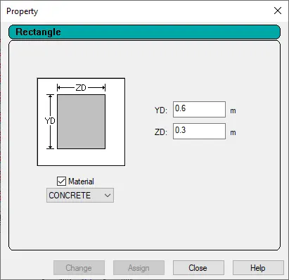
beams
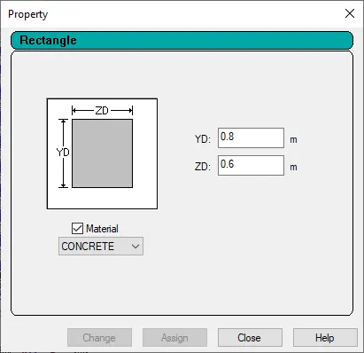
column
a) To assign the properties for beams:
- Go to select tab - click on parallel from beam section - select "TO X + CTRL + TO Z"
- Go to view tab - selected view
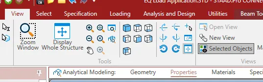
- provide assignment method as "assign to selected beams" - assign - yes
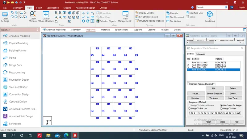
- Repeat this process for outer beams
- All properties are asign to beams
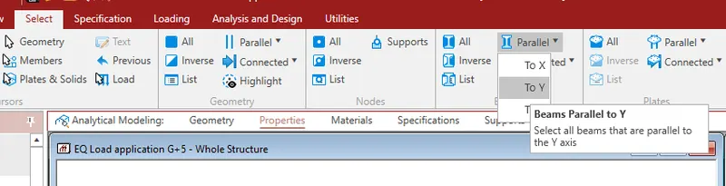
b) To assign the properties for coloums:
- Again go to select tab -choose the parallel to Y from beam section
- Click on selected objects from view section in view tab
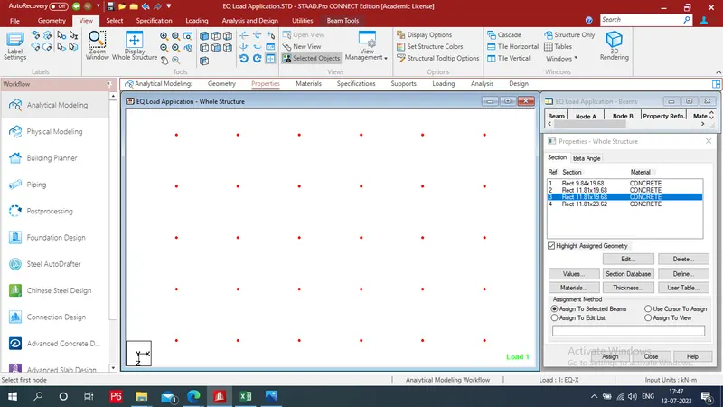
- Select section 2- choose inner columns - "assign to selected beams" - assign - yes
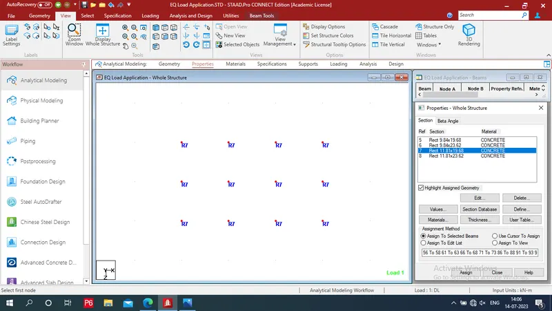
- Select on section 8
- Then go tu select tab - clcik on attribute form attribute section - missing property - select missing property
- Check box of "assign to selected beams" - assign - yes
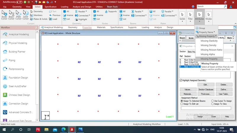
- Properties are assign to column
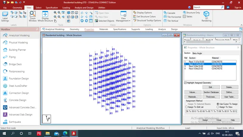
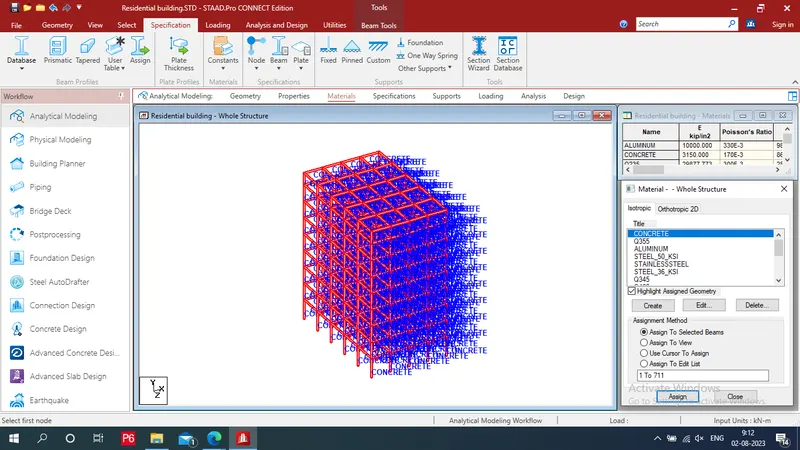
Step 4: To Apply material:
- Go to material tab - select concrete - Assign to view - assign - yes
- Material is assign to beam
Step 5: To provide Supprots:
- Go to next tab as a Supports Click on create
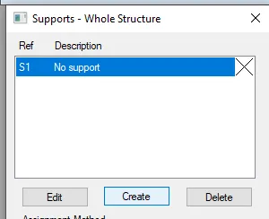
- Provide fixed support - Add - Close
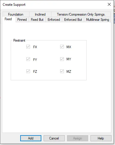
- Go to view tab select front (5th) view
- Then assign them to the drawing by using "use cursor to assign" - select bottom nodes- assign .
- Click on 3D view
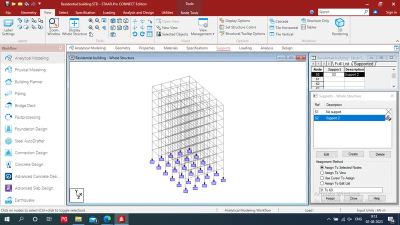
Step 6: To Apply Loading:
a) Definitions of seismic load:
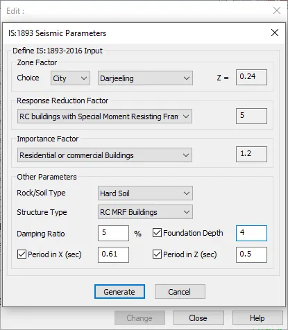
- Click on seismic definitions - add
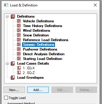
- Select type: IS1893 (part 1):2016 - Generate
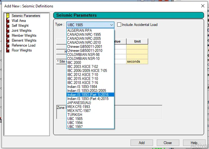
- Provide following data which we are calculate and some are given at above questions - Generate
- Dead load as pressure : - 10KN/M^2 (for typical floors) - check box of Group - Provide range - ADD
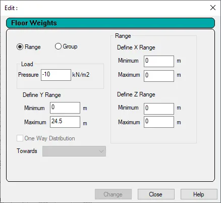
- Click on Floor weights - Live load as pressure : - 4KN/M^2 ( For typical floor) - Provide for according range by similar process
- Dead load as pressure : - 8KN/M^2 (for roof floors) - Provide for roof level -add - close
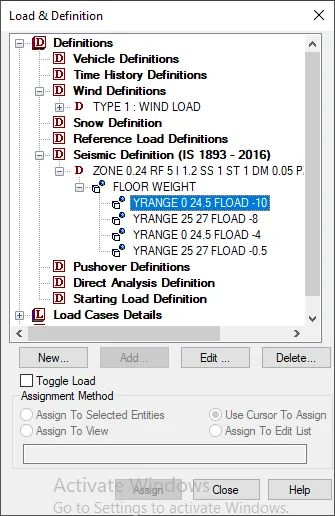
b) Apply seismic load:
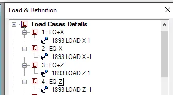
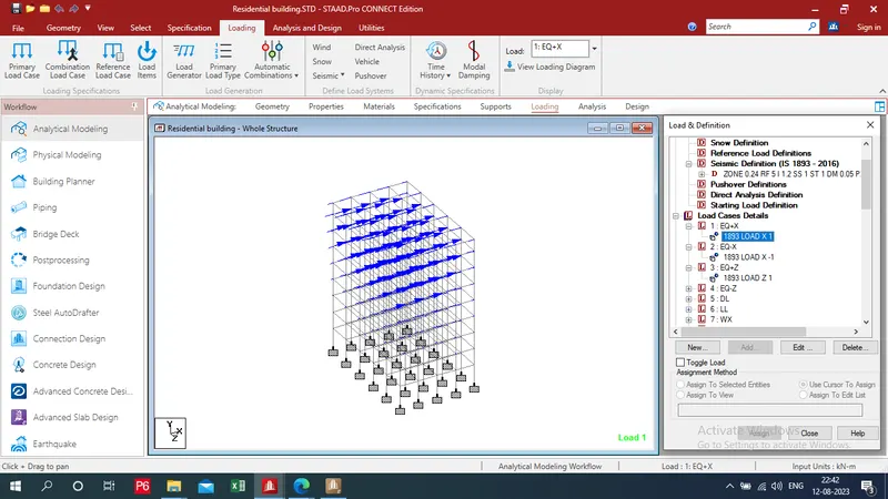
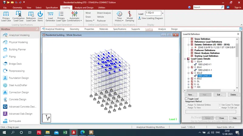
- Go to loading tab and click to load cases details and then click to add and create seismic load cases as EQ+x & EQ-X & EQ-z & EQ+z
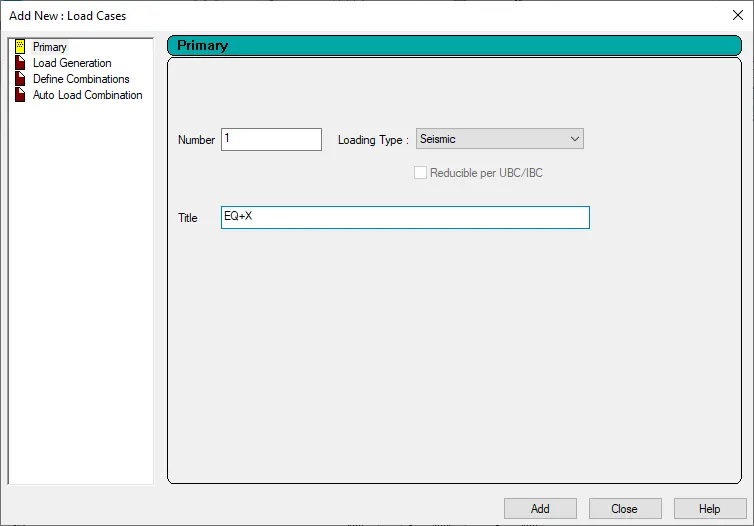
- Now click to EQ + x click to add then add seismic load as 1
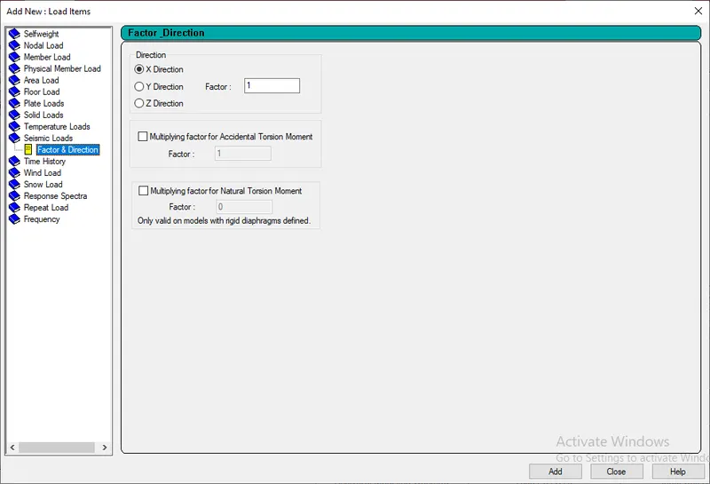
- Repeat these process for other seismic load and provide negative value for negative load with appropriate load direction
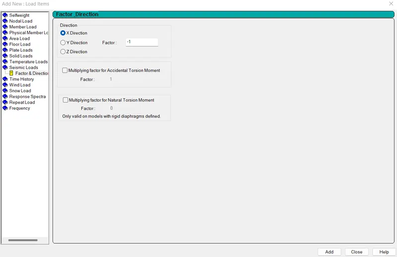
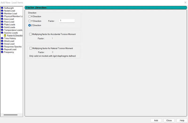
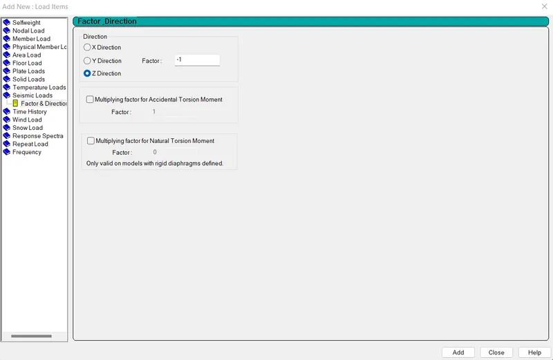
- All the Earthquake loads have been defined and apply successfully.
c) Definitions of wind load:
- Then go to the wind defination and click to add.
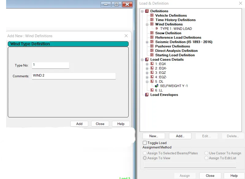
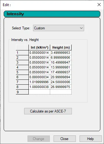
- Now click to new wind load case and click to add then input the wind intensity values which is calculated above. Finally click to add.
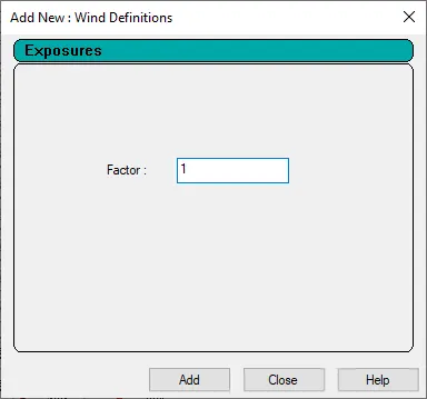
- Then provide exposure value as a 1 - add
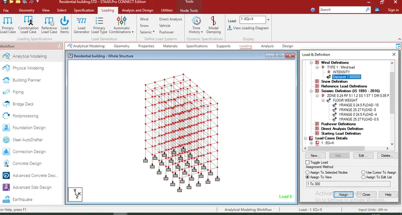
- Then asign it to view - assign
d) Apply wind load:
- THen click to load case details and click to add then add wind load case as WX and WZ
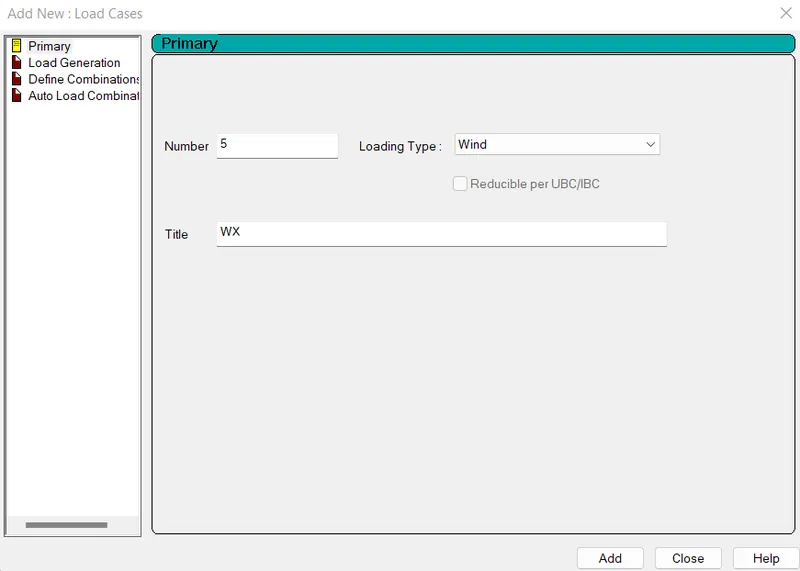
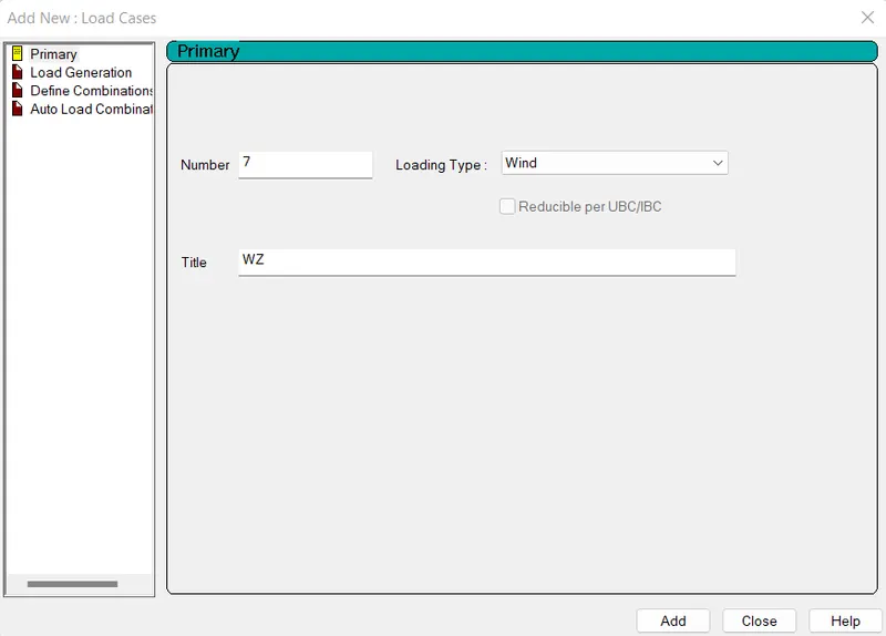
- click to WX and click add input the values
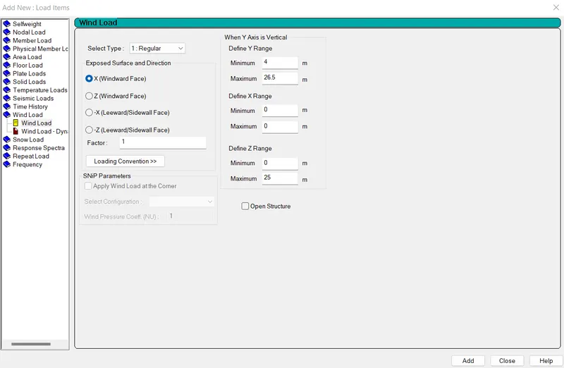
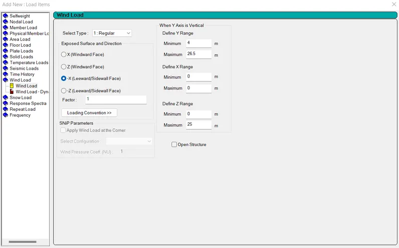
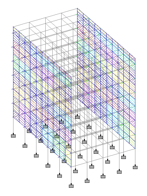
- Click to WZ and add input values
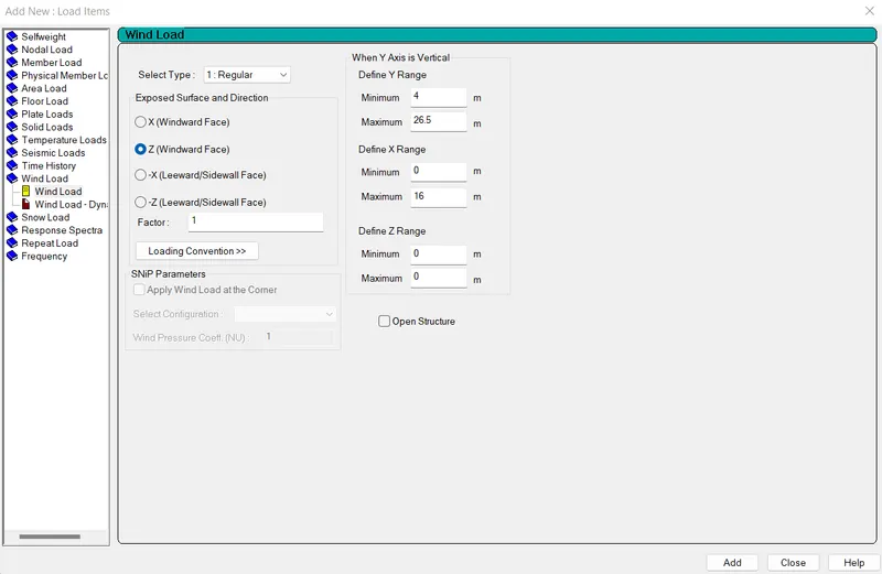
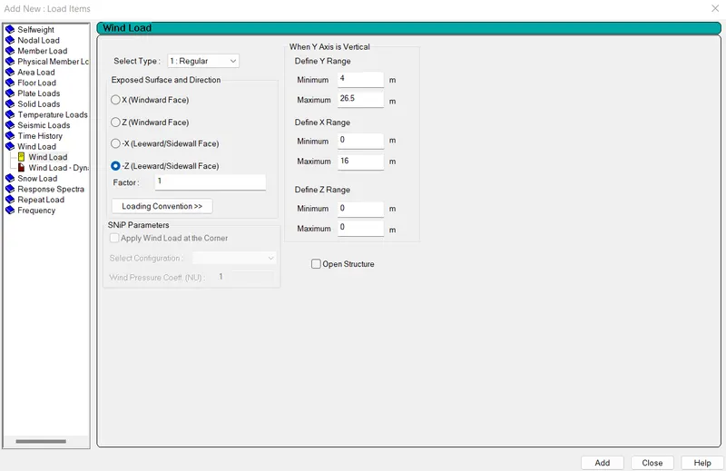
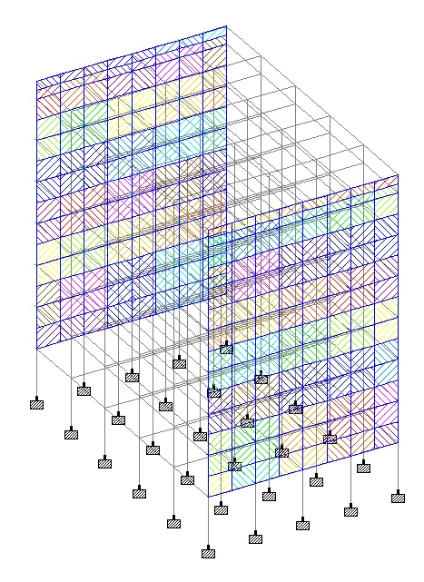
- All the wind loads have been defined and apply successfully.
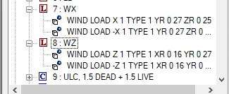
e) Apply Dead load:
- Add new load case as dead load and live load
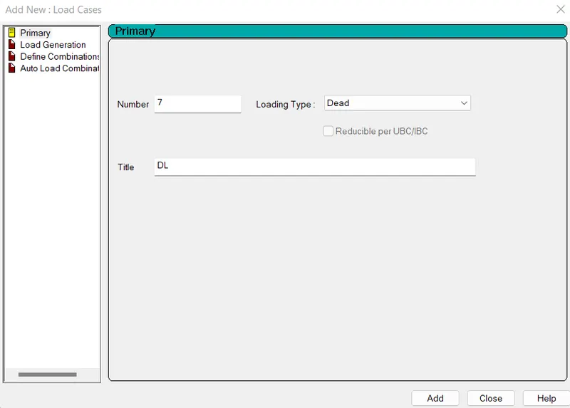
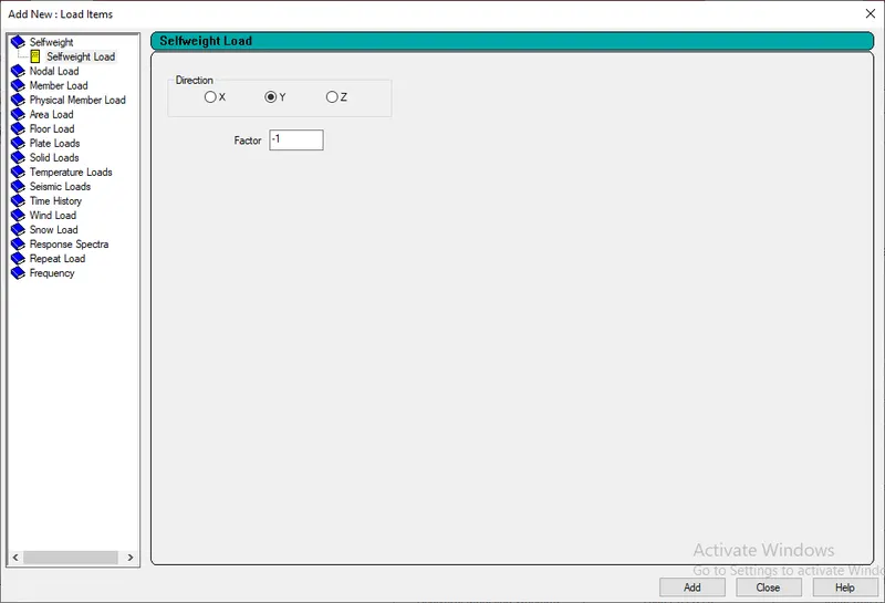
- Now add self weight under dead load case
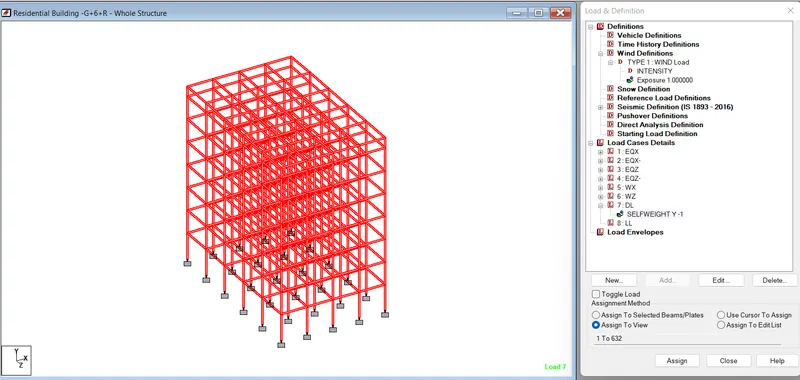
- Then assign it to the whole view
- After that assign the dead load for floor and roof
- Again select DL - Add - upto 7th floor as -10 KN/m^2 and for roof -8 KN/m2
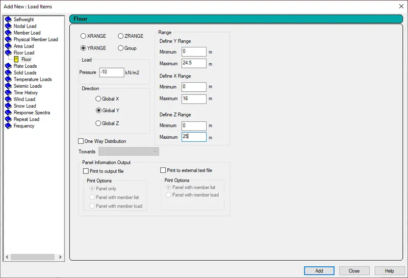
For Floor
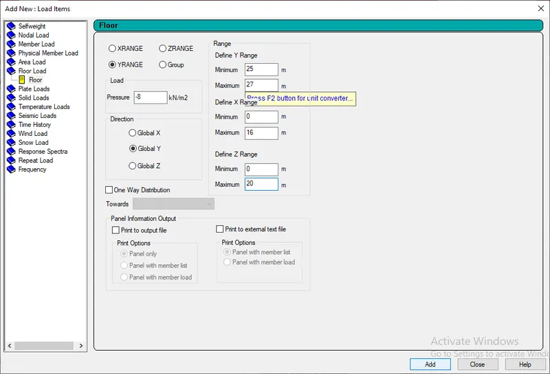
For Roof
- Assign them according to range of floor
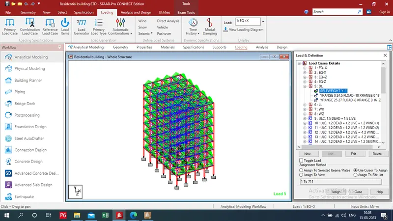
- Assign all dead loads to building
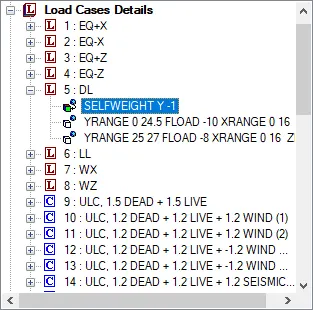
f) Apply live load:
- Click to add under Live load and go to floor load and add -4 KN/m2 for seven floors and add -1.5 KN/m2 for roof.
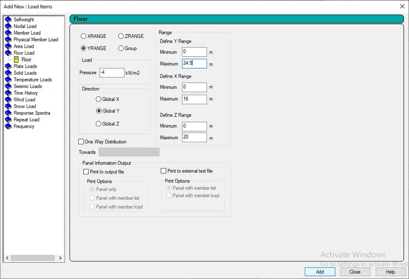
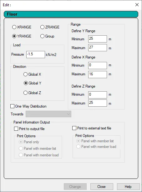
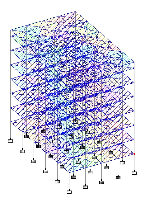
- Assign all live loads to building
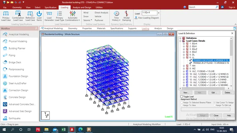
g) Apply load combination:
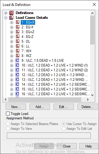
- Select Load cases deatail - click on auto load combination
- chooses load combination caod: IS456/800 - select load combination category - Click on generate load -add
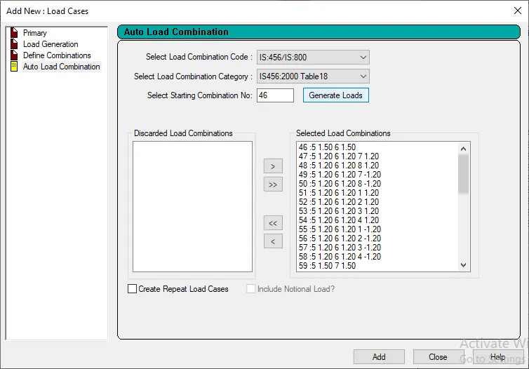
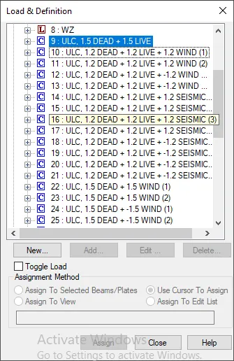
- Assign all loads to building
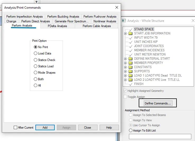
Step 7: Do Analysis:
- After going to analysis tab "Define command" - select perform analysis - add - close
Step 8: Assign the design parameters and commnads :
- Select material type
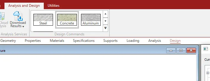
- Select IS456 as a current code
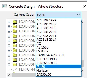
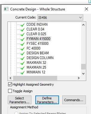
- Go to design Define parameters for concrete
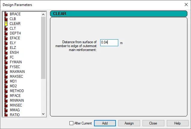
- Then click to define parameter
- clear cover as 40mm for column
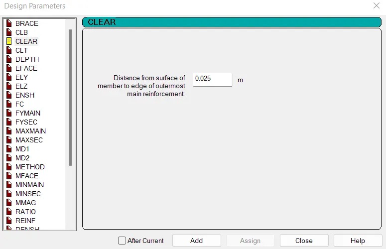
- Define clear cover as 25mm for beam
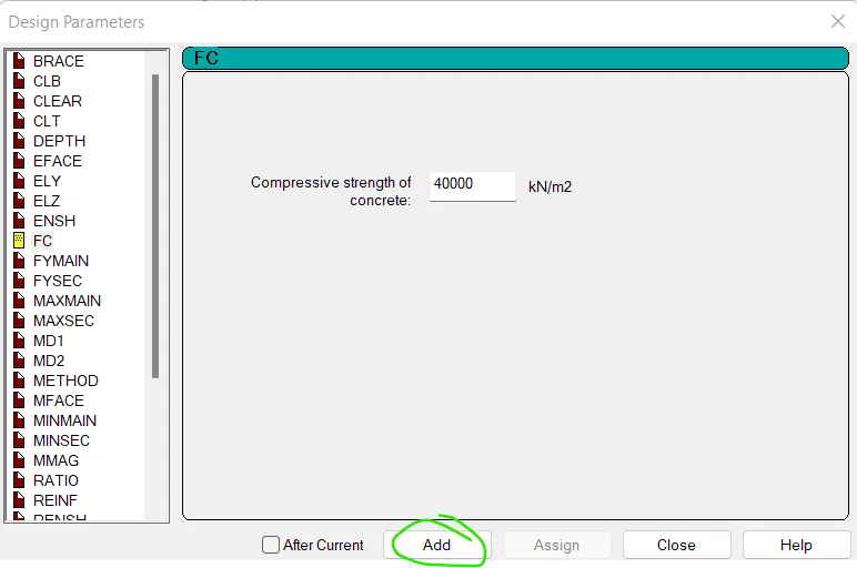
- Define characteristic compressive strength of concrete as M40 = 40000 KN/m2
- Define main reinforcement as FE415 and secondary reinforcement as FE415
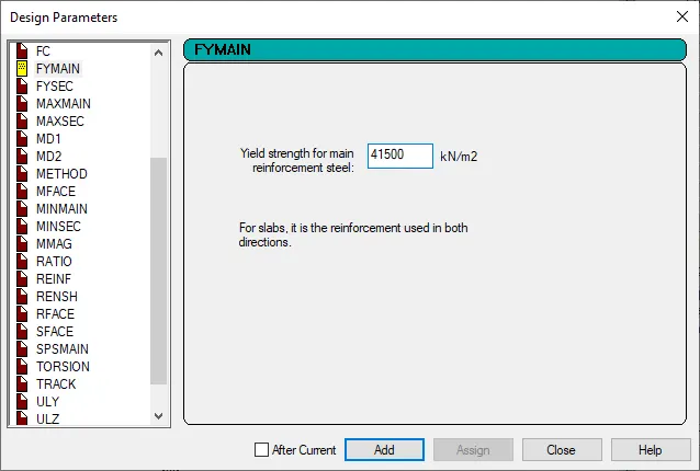
- Assign all the design parameters to the specified objects.
- Also assign remaining paramters
- Go to design tab and select concretye design and click to command option and add design beam and design column.
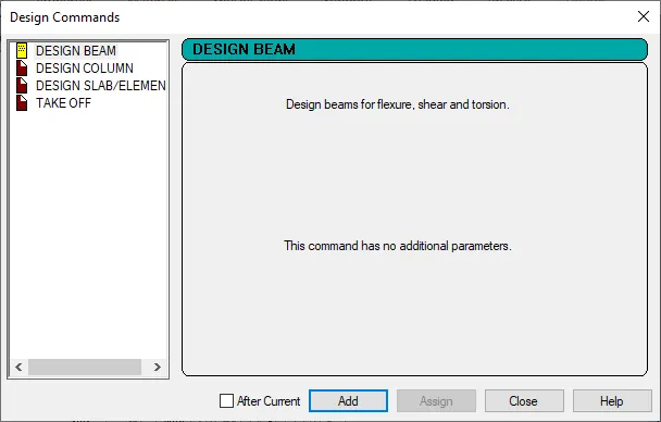
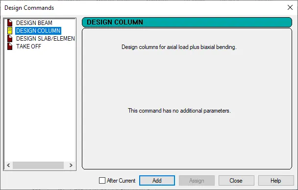
- Then assign beam design to beam and column design to column
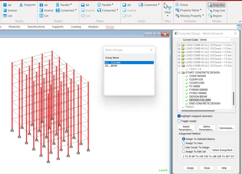
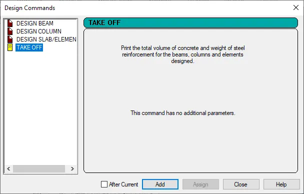
- Assign it by method of assign to view - assign
- Assigning all prameters and commands
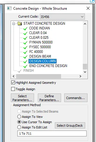
Step 9: Design by run analysis :
- Run analysis from analysis and design tab
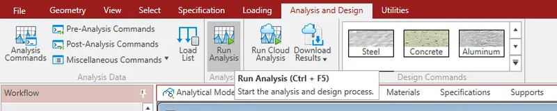
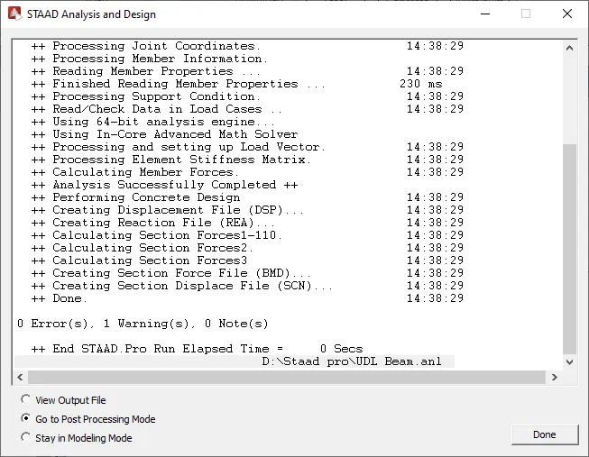
- Click on Go to post processing mode - Done
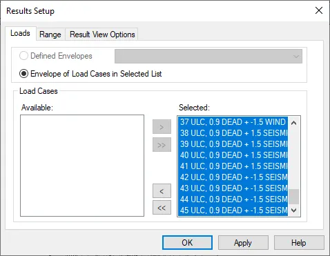
- Select loads - > - Apply - Ok
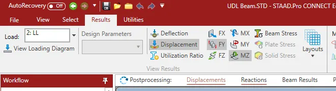
- Click on displacement, MZ we get BMD and click on FY we get sfd
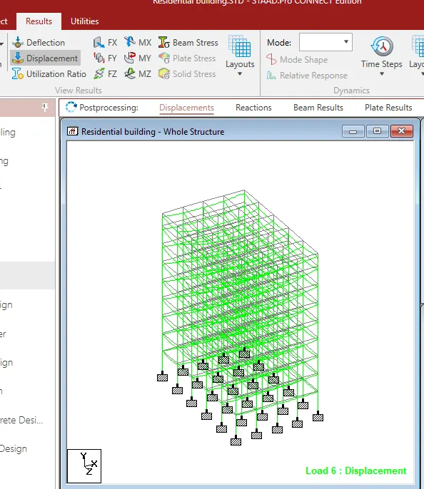
Displacement
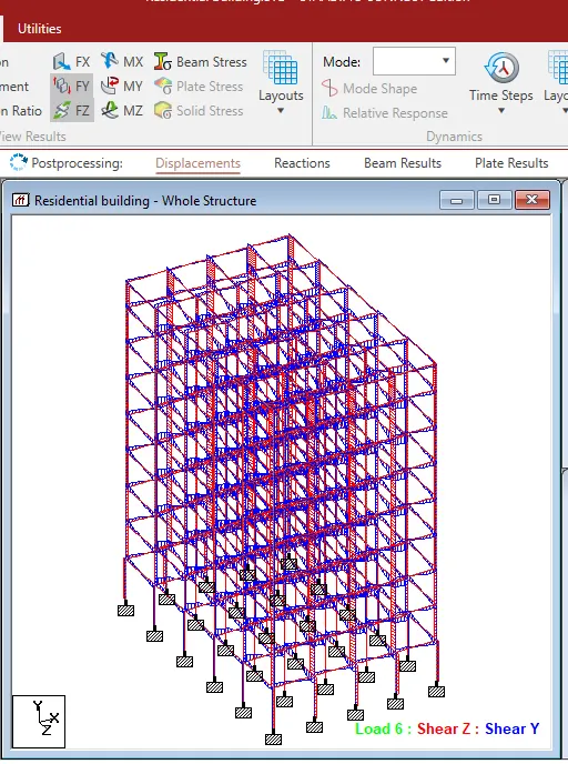
SFD
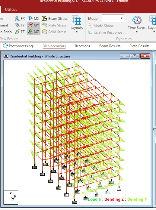
BMD
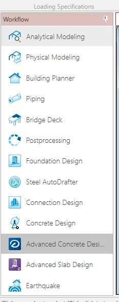
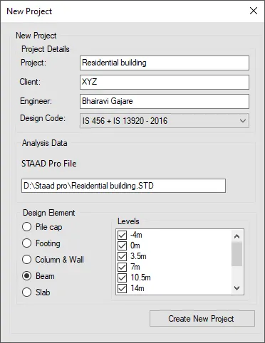
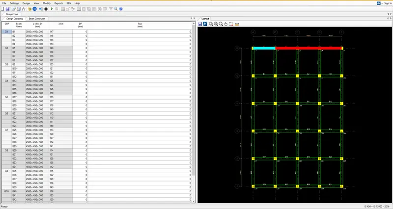
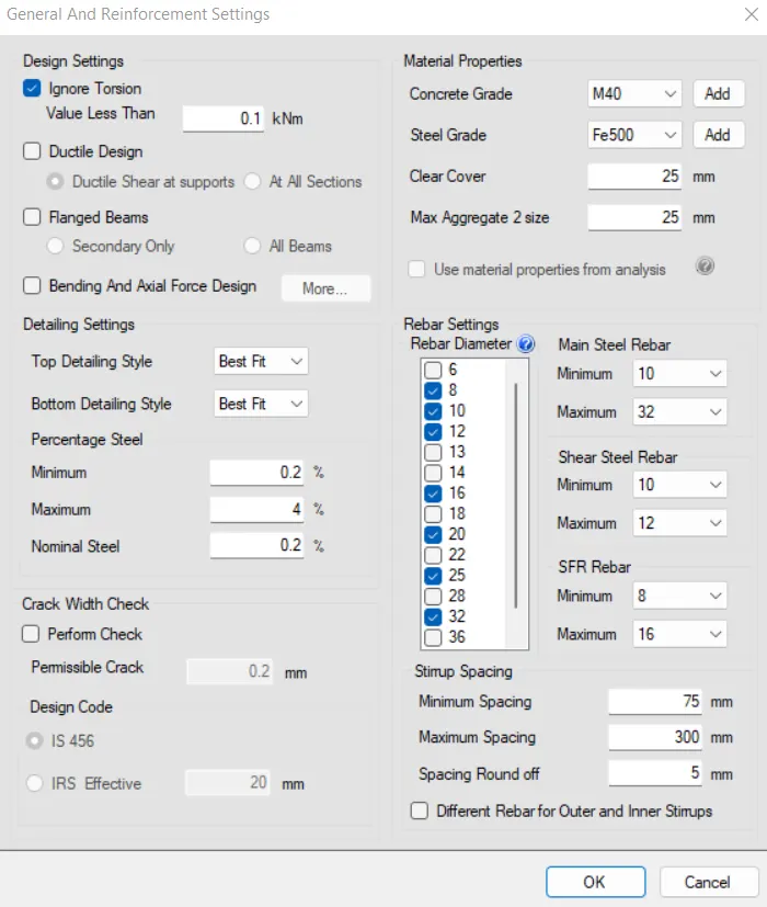
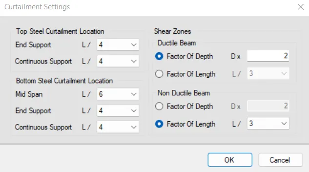
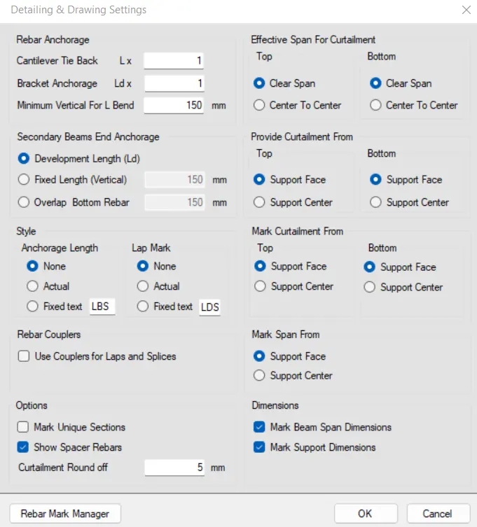
STEP-6: Do analysis of load cases
i) Once setting is done
ii) Click on Design and Click on Auto Design
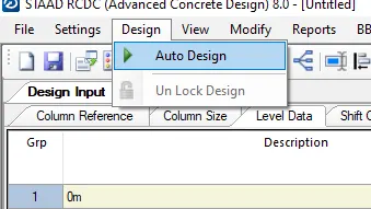
iii) All the load cases which we have defined will come
iv) Select the Load type
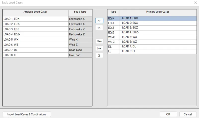
v) Click on Okay
vi) Click on Add from Ananlysis option for adding Load combinations
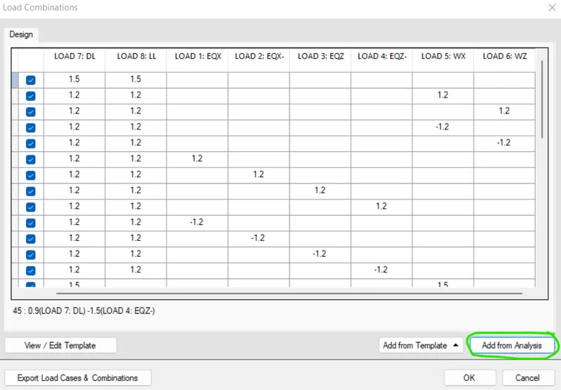
vii) Click on Okay
STEP-7:
i) Once you click Okay
ii) Software will design the beams
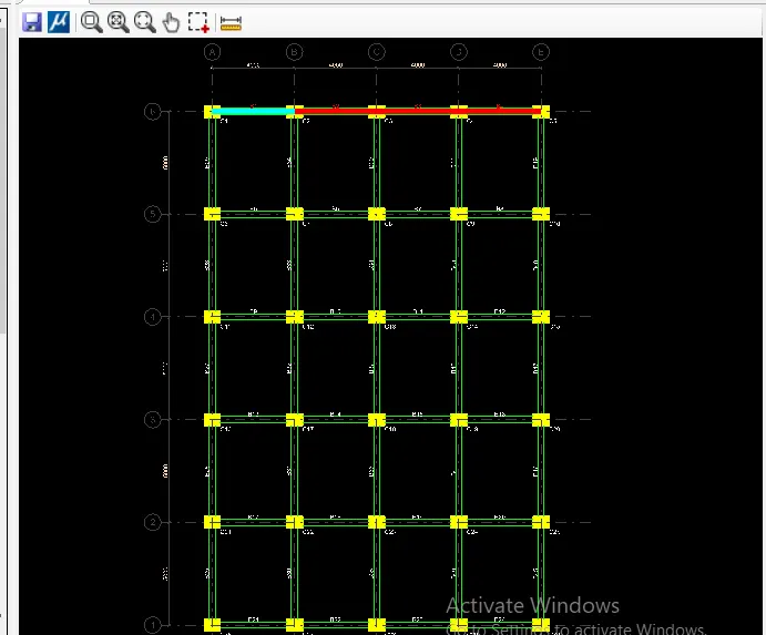
iii) As we can see all the beams are in Green colour
iv) So all the beams are passed
v) And We can see the design also
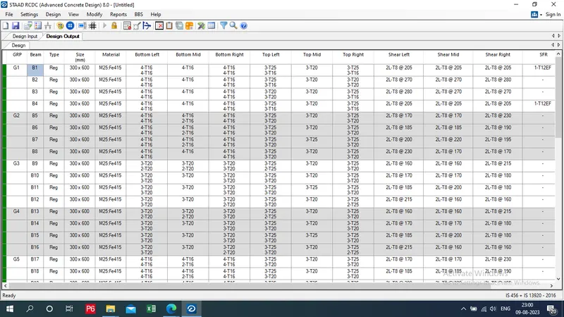
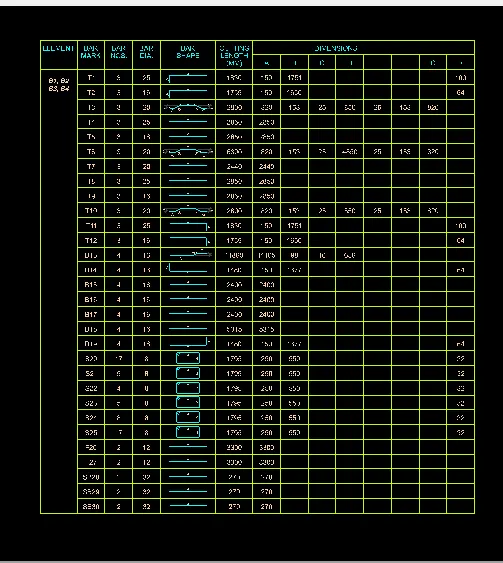
STEP 8: Preparing BBS:
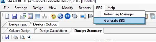
i) For BBS Click on BBS
ii) Click on Generate BBS
iv) We can select All beams or we can select group wise
v) Select B1-B2-B3-B4
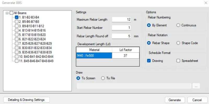
vi) Click on Generate
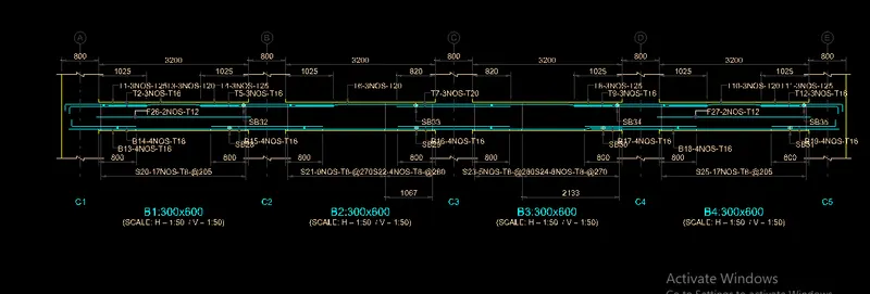
- BBS is prepared for B1-B2-B3-B4
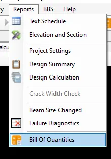
STEP-8: Create estimation:
i) Click on report - select bill of quantities
ii) Provide rates and area
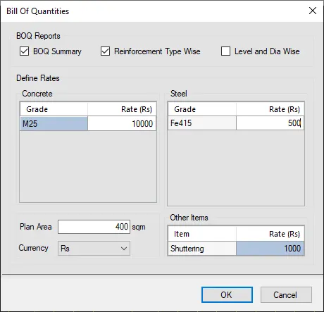
iii) Click ok
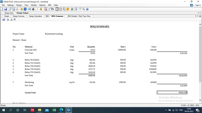
STEP-9: Design summary
i) Click on Report
ii) Click on Design Summary
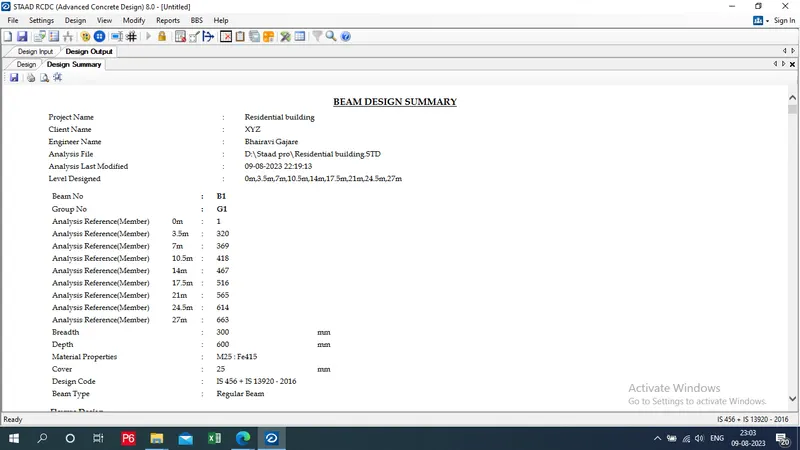
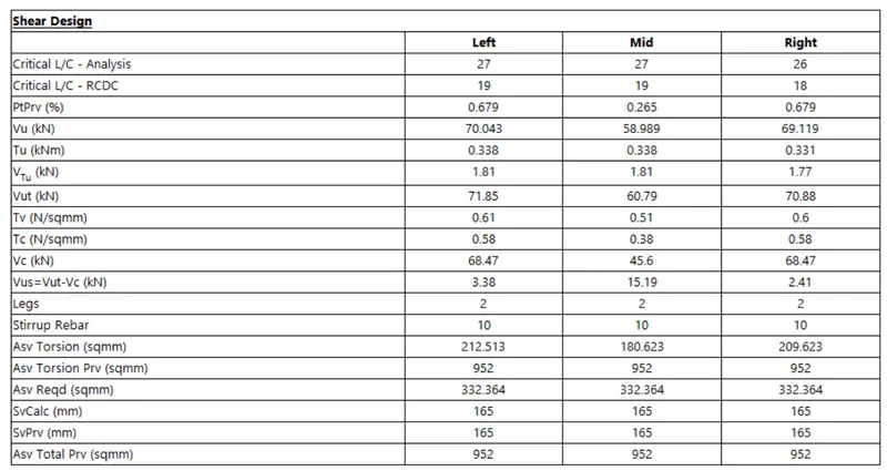
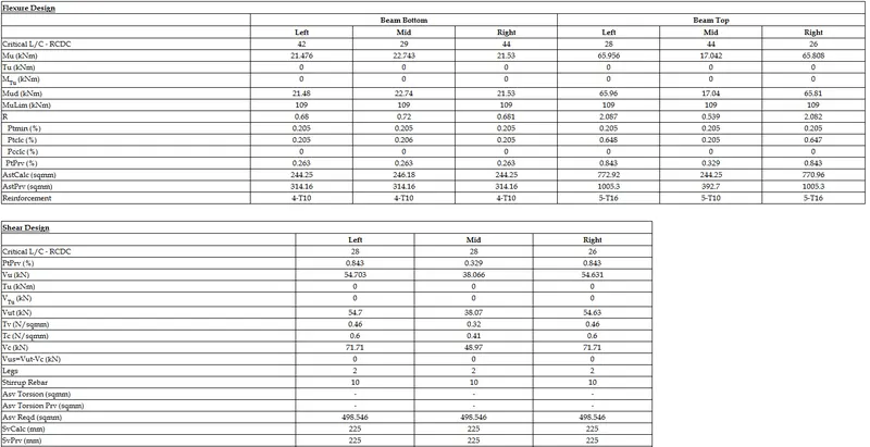
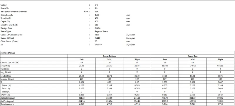
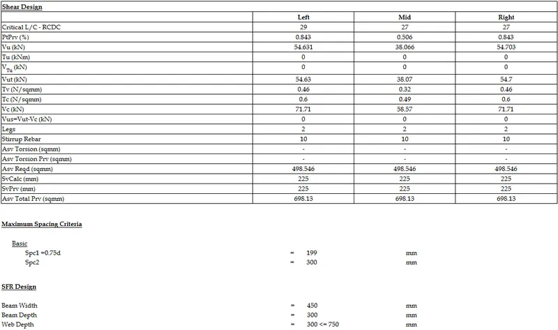
Beam Design Calculation Report:
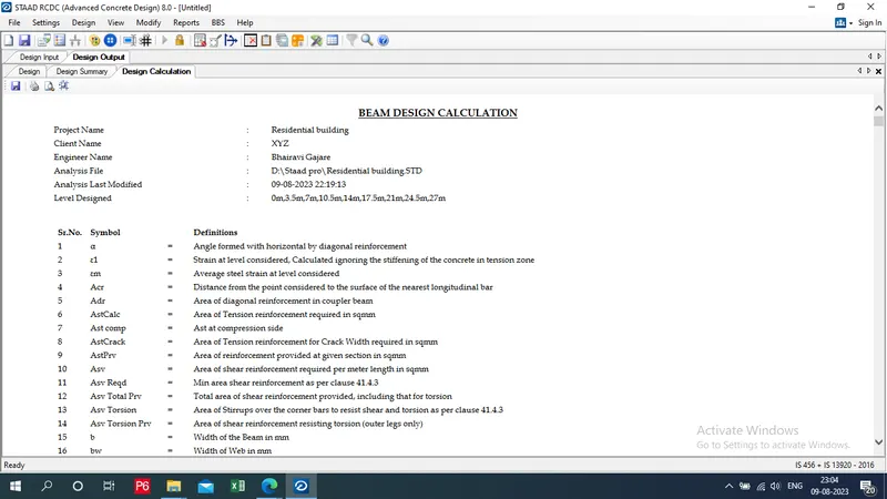
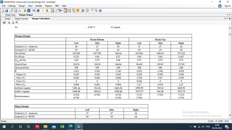
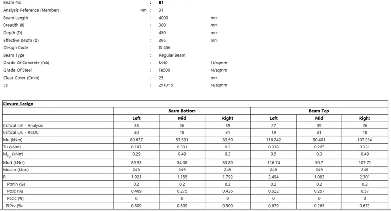
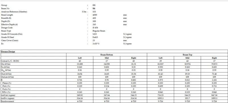
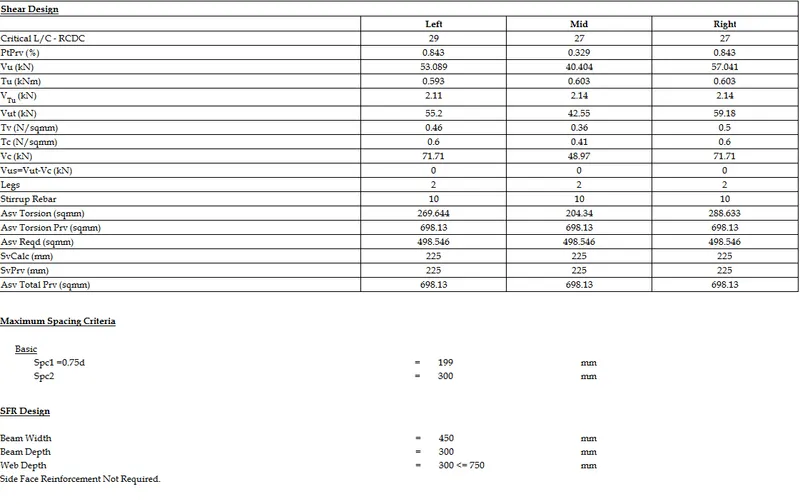
RCDC Design of column:
Similarly Follow the same procedure for Column Also
- Click on column and wall - create new project
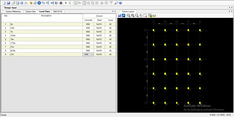
As we can see grids are automatically created with column mark
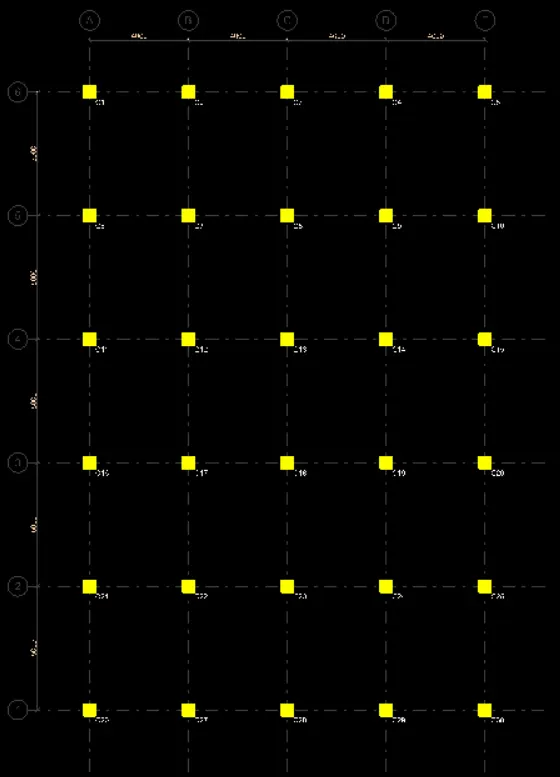
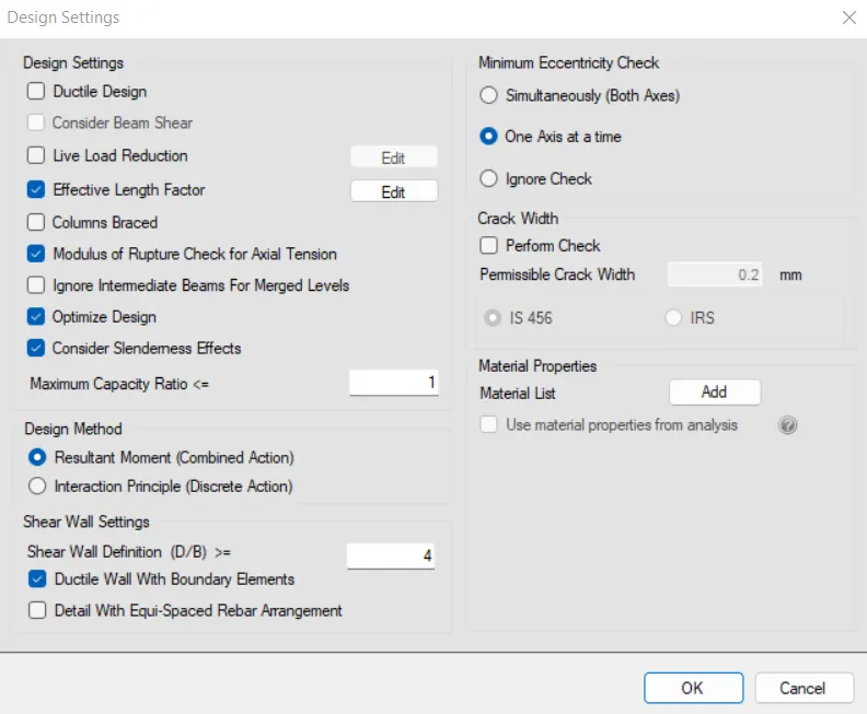
ii) Setting - Design Setting
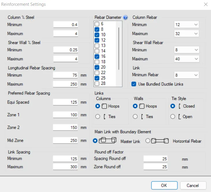
iii) Setting - Reinforcement Setting
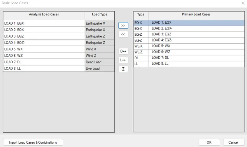
iv) Design - Auto Design
Select load cases and Load Combinations
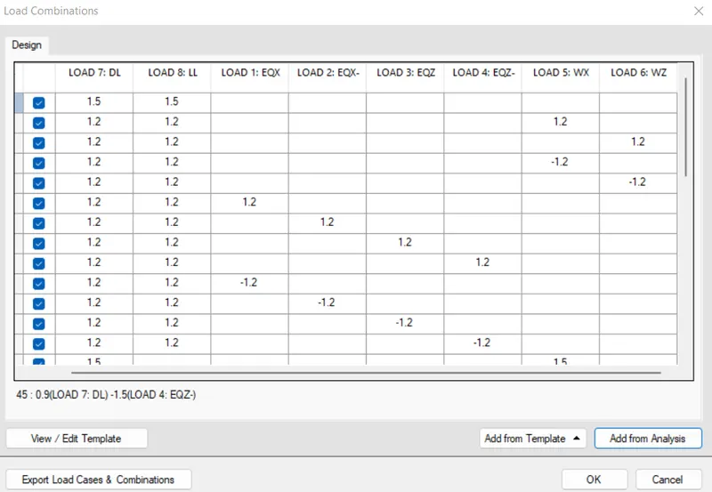
Click add from analysis
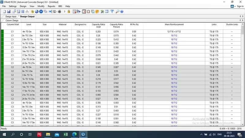
v) Design output
As we can see that Columns are perfect
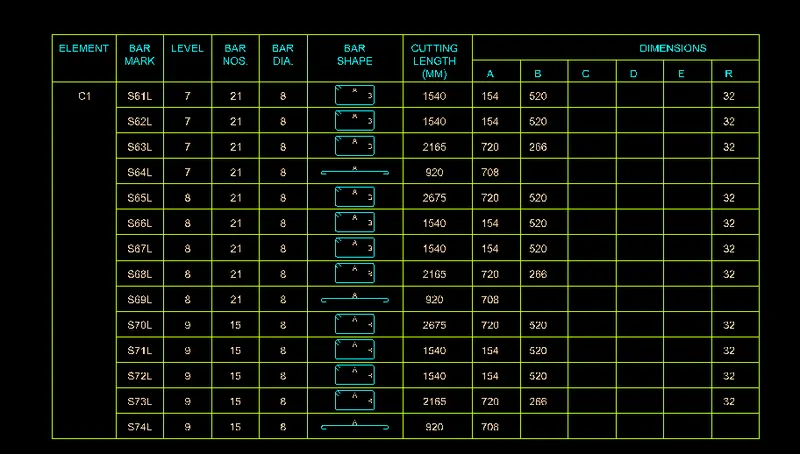
vi) BBS
Click to generate BBS
Select C1 column
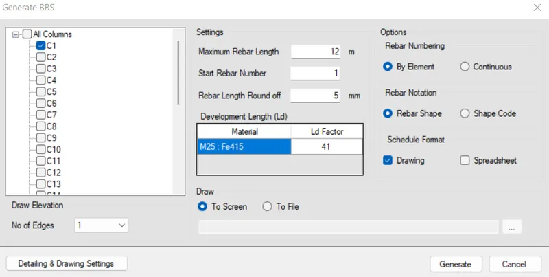
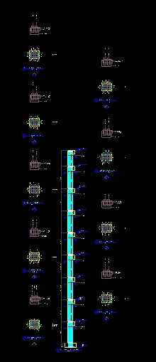
Click to generate
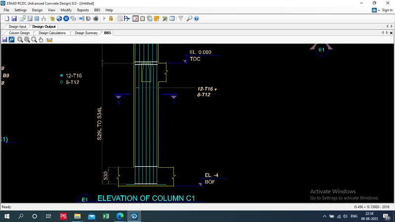
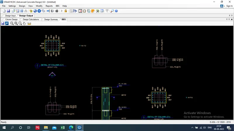
vii) Design Calculation Report for C1:
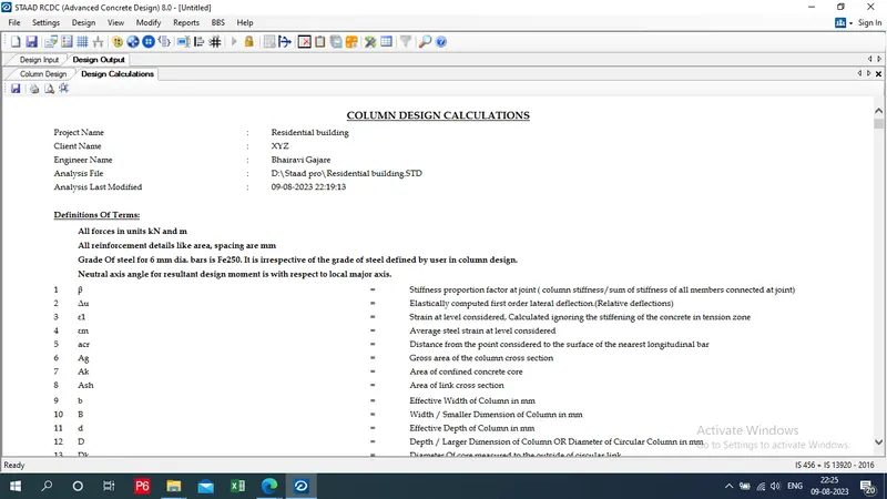
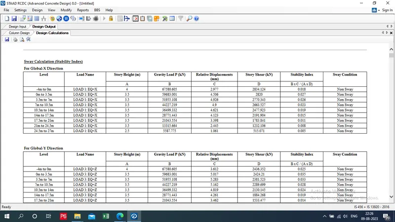
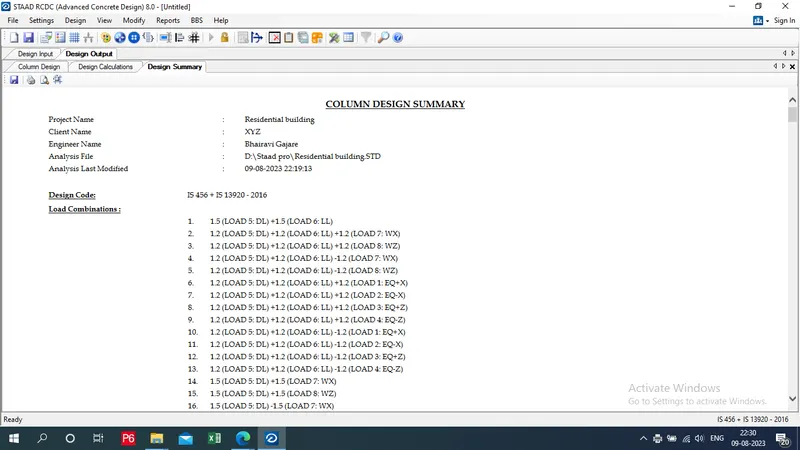
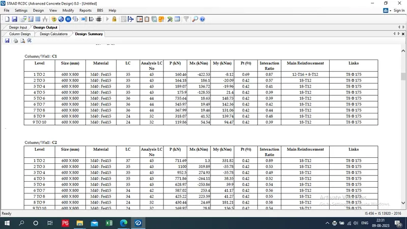
viii) Design summary Report:
ix) print of Report:
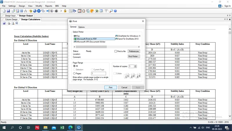
Click on print - provide convert to pdf option - print - give appropriate name and loaction we get a reprot in pdf format
4) Design Foundations using STAAD Foundation.
Step:-1 Open staad model
i) Open the model
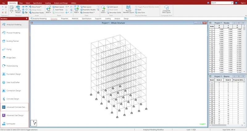
ii) Click on Staad Foundation
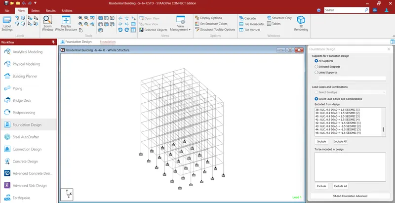
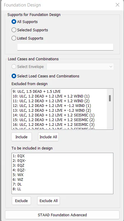
Include only Prime load cases
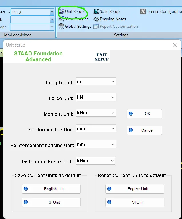
Step:-2 Unit Setup:
i) Set the unit system
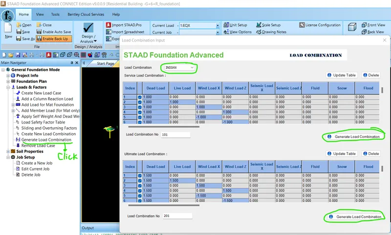
Step:-3 Generate load combination
Generate Service and ultimate Load combination
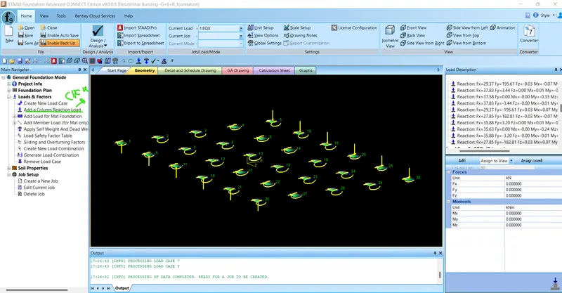
Then click to column reaction load
Step:4 - Create Job:
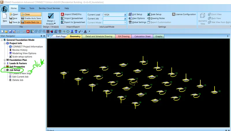
iii) clik on Job setup - Create a New Job
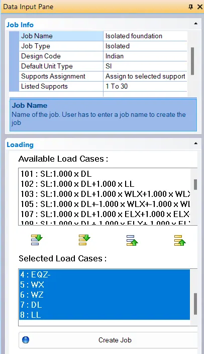
Then click to create job logo.
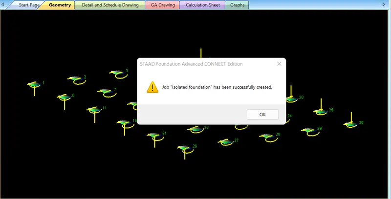
Step:5 - Apply Design Paramters
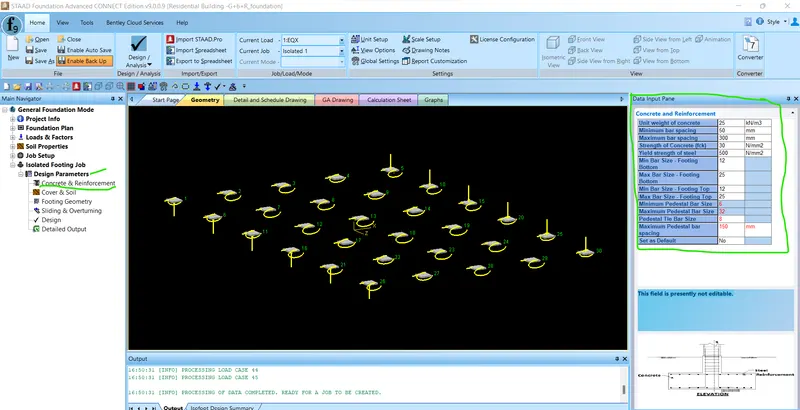
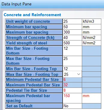
iv) Enter concrete and reinforcement details
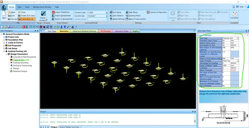
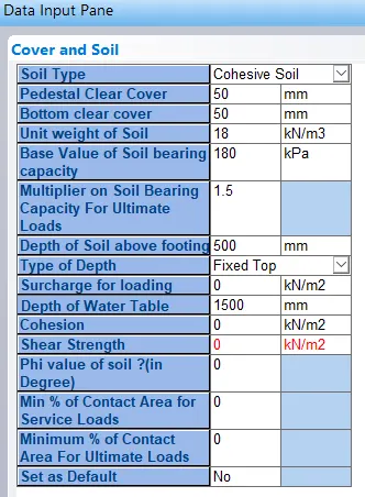
v) Enter Soil property
vi) Enter Footing Geometry
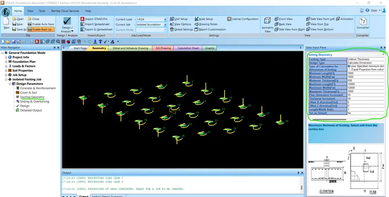
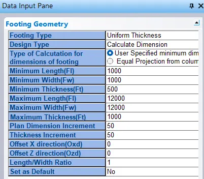
vii) Provide sliding & overturning data
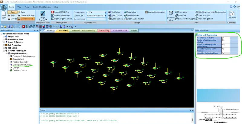

Step:6- Run Design:
vi) Click on Design
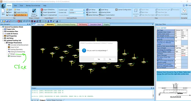
vii) Once design is completed you will see the details of footing
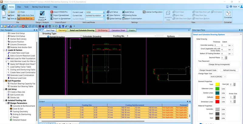
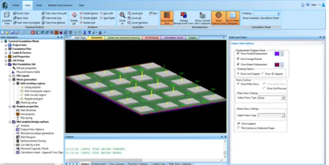
viii) Design output of footing
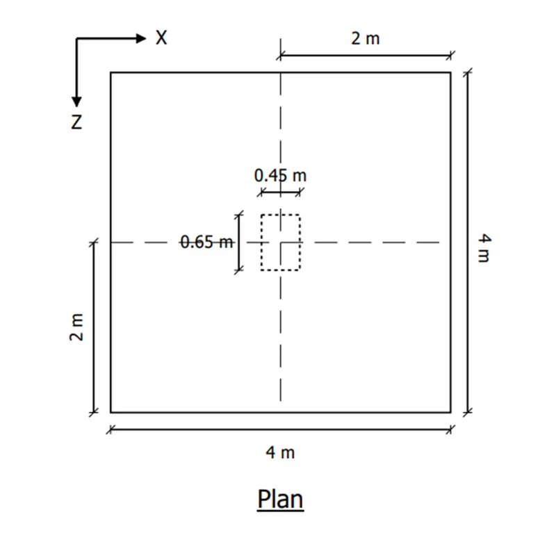
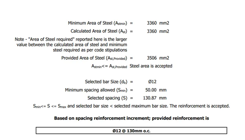
Result:-
The Design of G+6+R (Residential building) is successfully completed. Also following criteria of the question is successfully answered.
- Prepare a Design Basis Report for the project
- Create structural model using STAAD Pro Connect Edition
- Prepare DL, LL, WL and EQL load calculations as per IS 875 standards
- Design slab element using MS – Excel
- Design beam and column element using STAAD RCDC. Attach the design calculation report.
- Design Foundations using STAAD Foundation.
- Prepare bar bending schedule for beam and column using STAAD RCDC
- Attach necessary sketches and drawings wherever required.
Conclusion:-
All the results has been displayed and EXCEL files regarding slab design, wind load calculation & earthquake load caculation is attached in this project. Moreover, I have attached main staad model and analysis file along with staad foundation design file, staad RCDC column design file and RCDC beam design file.