Project 1
Project 1:
1) Design a battery pack for a car roughly 150 Kw with 120 V. Use 3500 mAh 3.6V nominal NMC chemistry cell.
a. Design the battery pack configuration.
b. Draw the BMS topology for this battery pack.
Aim:
To design a battery pack configuration, draw the BMS topology using given data and Build a 3S2P battery pack configuration with generic battery block using Matlab/Simulink.
Battery Management System:
Battery management system (BMS) is technology dedicated to the oversight of a battery pack, which is an assembly of battery cells, electrically organized in a row x column matrix configuration to enable delivery of targeted range of voltage and current for a duration of time against expected load scenarios.
The oversight that a BMS provides usually includes:
- Monitoring the battery
- Providing battery protection
- Estimating the battery’s operational state
- Continually optimizing battery performance
- Reporting operational status to external devices
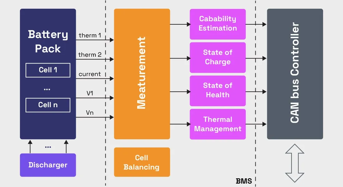
Here, the term “battery” implies the entire pack; however, the monitoring and control functions are specifically applied to individual cells, or groups of cells called modules in the overall battery pack assembly. Lithium-ion rechargeable cells have the highest energy density and are the standard choice for battery packs for many consumer products, from laptops to electric vehicles. While they perform superbly, they can be rather unforgiving if operated outside a generally tight safe operating area (SOA), with outcomes ranging from compromising the battery performance to outright dangerous consequences. The BMS certainly has a challenging job description, and its overall complexity and oversight outreach may span many disciplines such as electrical, digital, control, thermal, and hydraulic.
Solution:
Data:
Power - 150 kw
Voltage - 120 v
Cell Nominal Capacity - 3500 mAh
Cell Nominal Voltage - 3.6 v
So, Battery Ampere Hour = Power/Voltage = 15o kw/120 v = 1250 Ah
Now we will find number of cells in series & parallel.
No. of Cells in Series:
Number of cell in series = Required Voltage/Cell Nominal Voltage
Number of cell in series = 120/3.6 = 33.33
Now we will take round off, We have two cases
Condition 1- No of cells in series = 34
Condition 2- No of cells in Parallel = 33
Condition 1
Nominal battery voltage = cell nominal voltage * No of cells in series
= 3.6 * 34
= 122.4 V
Condition 2
Nominal battery voltage = cell nominal voltage * No of cells in series
= 3.6 * 33
= 118.4 V
It is always better to prefer higher voltage. Number of Cells in Series = 34.
No. of Cells In Parallel:
No of cell in parallel = Rated Current / Cell Nominal Capacity
No of cell in parallel = 1250/3.5 = 357.14
Case 1- Roundoff to 357
Battery capacity = rated capacity of a cell * no of cells in parallel
= 3.5* 357= 1249.5 Ah
Case 2- Roundoff to 358
Battery capacity = rated capacity of a cell * no of cells in parallel
= 3.5* 358= 1253 Ah
Now we are considering no of cells in parallel is 358
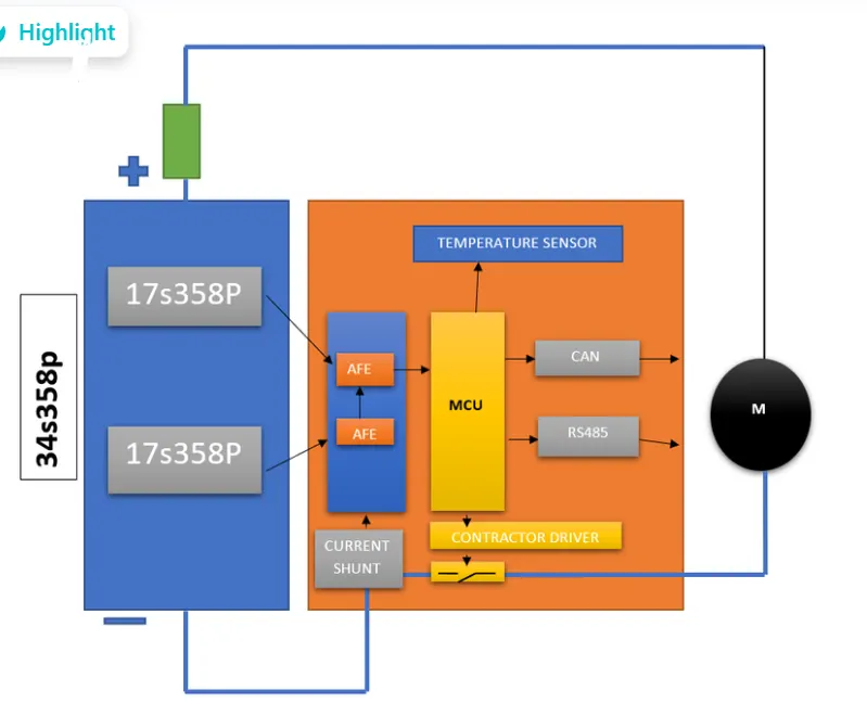
So Battery Pack Configuration is 34S348P.
Now we need decide the BMS topology for our battery pack.
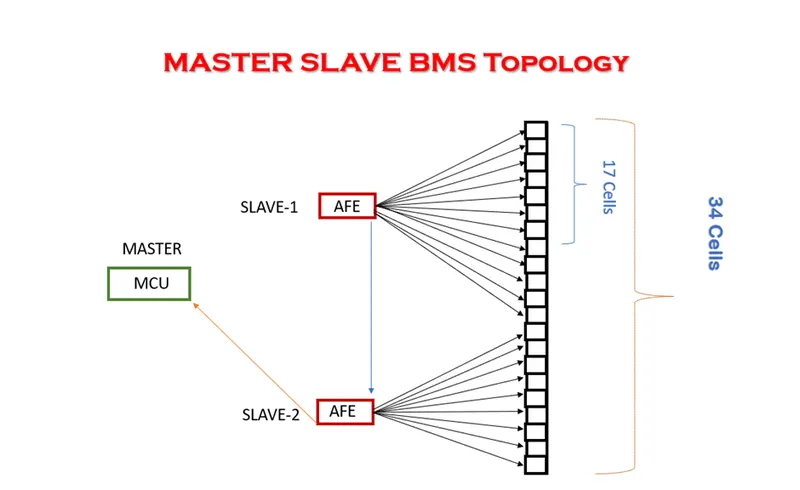
Since we have 34 no of cells in series we cannot use centralized topology and Distrubuted topology Since they only support a maximum 18 cells.
Modular topology usually use for large no of cells in series.So here we go for master slave topology .
As the BMS Supports the max 18 cells in series so we need to divide the 34 series cells to 18 cells series sub battery packs
So here sub battery pack is one with 17 cells in series and one with 17 cells in series.
So in our master slave topology there will 2 slave AFE in which one will collect the data of 17 cells in series and other will collect the data of 17 cells in series
2) Build a 3S2P battery pack configuration with generic battery block using Matlab/Simulink.
Solution:
Total number of cells in battery pack = no.of cells in series * no.of cells in parallel
= 3*2
=6 cells
Series connection of a battery:
Batteries are connected from teminal to terminal in a way that the +ve terminal one battery is connected to -ve termnal of the other battery and -ve terminal of one battery is connected to +ve terminal of other battery.
Parallel connection of a batteery:
Batteries are connected from terminals to same terminals of the other batteries that is +ve terminal of one battery is connected to +ve terminal of other battery and -ve terminal of one battery is connected to -ve terminal of other battery.
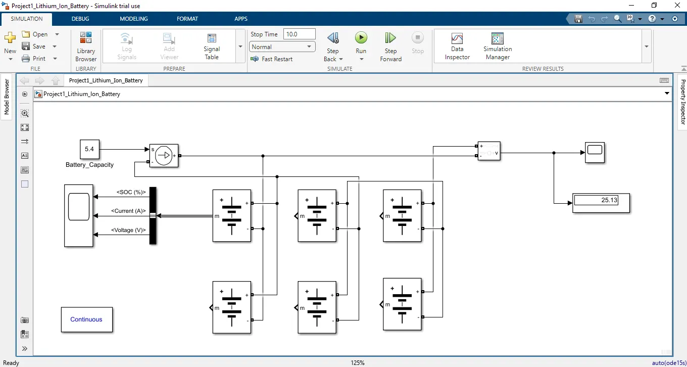
The battery pack model is shown below
Model explanation:
The voltage is measured bu using voltage measurement and is connected across the battery pack and the scope is connected to bus selector and is connected to battery measurement port for measuring the SOC,voltage & current of the cell the constant block is connected to controlled current source and is given load to the battery pack.
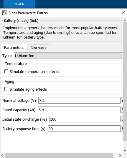
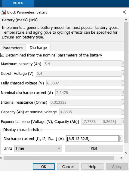
The parameter given inside the battery is given below:-
- Nominal voltage of a cell 7.2V
- Rated capacity of a cell 5.4Ah
- Maximum voltage of a cell 8.3V
There fore ,
Nominal voltage of the battery pack = no.of cell in series * nominal voltage of a cell
= 3 * 7.2v
= 21.6 V
Rated capacity of the battery pack = no.of cell in parallel* rated capacity of a cell
= 2 * 5.4Ah
= 10.8Ah
The model is for an 21.6V 7 with 10.8Ah battery capacity
Overall voltage of the battery pack = maximum voltage of the battery * no. of cells in series
= 8.3V * 3
= 25 v
= 25 V
Important Parameters:
Capacity: The capacity of a battery or cell is defined as the amount of energy that it can deliver in a single discharge. Battery capacity is normally specified in amp-hours (or milli-amp-hours) or as watt-hours.
Charge rate or C-rate : The definition of the charge rate or C-rate of a battery or cell is the charge or discharge current in Amperes as a proportion of the rated capacity in Ah. For example, in the case of a 500 mAh battery, a C/2 rate is 250 mA and a 2C rate would be1 A.
Constant-Current Charge: This refers to a charging process where the level of current is maintained at a constant level regardless of the voltage of the battery or cell.
Constant-Voltage Charge: This definition refers to a charging process in which the voltage applied to a battery is held at a constant value over the charge cycle regardless of the current drawn.
Cycle Life: The capacity of a rechargeable cell or battery changes over its life. The definition of the battery life or cycle life of a battery is number of cycles that a cell or battery can be charged and discharged under specific conditions, before the available capacity falls to a specific performance criteria - normally 80% of the rated capacity.
Cut-off voltage: As a battery or cell is discharged it has a voltage curve that it follows - the voltage generally falling over the discharge cycle. The definition for a cell or battery of the cut-off voltage cell or battery is the voltage at which the discharge is terminated by any battery management system. This point may also be referred to as the End-of-Discharge voltage.
Energy Density: The volumetric energy storage density of a battery, expressed in Watt-hours per litre (Wh/l).
Power Density: The volumetric power density of a battery, expressed in Watts per litre (W/l).
Rated Capacity: The capacity of a battery is expressed in Ampere-hours, Ah and it is the total charge that can be obtained from a fully charged battery under specified discharge conditions
Self-Discharge: It is found that batteries and cells will lose their charge over a period of time, and need re-charging. This self-discharge is normal, but various according to a number of variables including the technology used and the conditions. Self-discharge is defined as the recoverable loss of capacity of a cell or battery. The figure is normally expressed in a percentage of the rated capacity lost per month and at a given temperature. The self-discharge rate of a battery or cell is very dependent upon the temperature.
Specific Energy: The gravimetric energy storage density of a battery, expressed in Watt-hours per kilogram (Wh/kg).
Specific Power: The specific power for a battery is the gravimetric power density expressed in Watts per kilogram (W/kg).
Scope Result:
Voltage
The voltage is dropped from 25.2v to 25.13v for this battery pack.
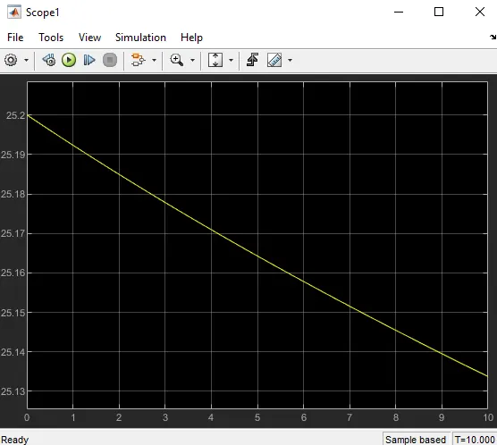
SOC, Current & Voltage graph given below.
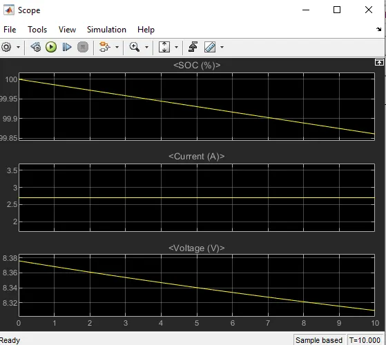
First plot shows SOC of the cell it is dropped from 100% to 99.86 %
Second plot shows Current of the cell it is nearly 2.7A
Third plot shows voltage of the cell it is dropped from 8.37v to 8.31volts
Here we have created model of battery pack configuration(3S2P) with battery block using Matlab/Simulink.