Project 1
1. Design a multi-storey Residential Building located in Bangalore using STAAD Pro Connect Edition. The specification must be as follows:
|
Building floors |
G + 6 + R |
|
Plan dimension |
B = 25m , L = 16m |
|
Storey Height |
h = 3.5m |
|
Soil |
Hard soil |
|
Use |
Residential Purpose |
|
Safe Bearing Capacity |
180 kN/m2 |
|
Maximum slab thickness |
150mm |
Assume suitable sections for structural elements. Follow IS456, IS1893 and IS 875
- Prepare a Design Basis Report for the project
- Create structural model using STAAD Pro Connect Edition
- Prepare DL, LL, WL and EQL load calculations as per IS 875 standards
- Design slab element using MS – Excel
- Design beam and column element using STAAD RCDC. Attach the design calculation report.
- Design Foundations using STAAD Foundation.
- Prepare bar bending schedule for beam and column using STAAD RCDC
- Attach necessary sketches and drawings wherever required.
- All stipulations, assumptions and design parameter must adhere to Indian Standards.
AIM: To design a multi-storey Residential building which is located in Banglore using the STAAD Pro Software.
PROCEDURE:
DBR-Design Basis Report:
- GIVEN DATA:
Building Floors : G+6+R
Plan Dimension : B = 25m,L = 16m.
Story Height : h = 3.5m.
Soil : Hard Soil.
Use : Residential Purpose.
Safe Bearing Capacity : 180 Kn/sq.m.
Maximum Slab thickness : 150 mm.
- Material Specification:
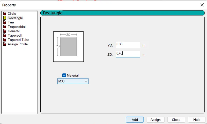
Assume the size of the beams : 0.30 X 0.45 m.
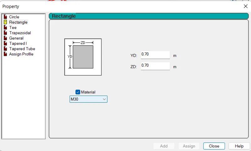
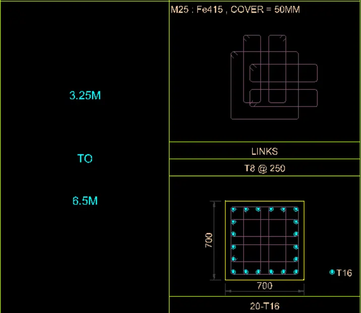
Assume the size of the column : 0.7 X 0.7 m.
- Loads Calculations:
Dead Load(IS 875 Part-l):
Dead Load on Floor:
Dead weight due to slab = 0.15 X 25
=3.75 KN/sq.m
Partitions : 1.5 KN/sq.m
Floor finish : 2.5 KN/sq.m
Miscellaneous : 1 KN/sq.m
Total Floor Load = 8.75 KN/sq.m.
Dead Load on Roof (IS 875 Part-l):
Dead Load on roof slab = 3.75 KN/sq.m.
Insulation and Water proofing = 0.5 KN/sq.m.
MEP Services = 0.5 KN/sq.m.
Miscellaneous = 0.5 KN/sq.m.
Total Roof Load = 5.25 KN/sq.m
- Live Load (IS 875 Part ll):
For Residential Building Live Load = 3 KN/sq.m.
For Roof Lie Load = 1.5 KN/sq.m.
Wind Load Calculation (IS 875 Part-lll):
(l) Design Wind Speed :
We know that:
Vz = Vb X k1 X k2 X k3 X k4,
where:
Vb = Basic Wind Speed (m/sec).
k1 = Risk Co-efficient (IS 875 Part-lll:2015 Table 1).
k2 = Terrain Roughness and height factor.
k3 = Topography factor (IS 875 Part-lll:2015 Clause 6.3.3).
k4 = Importance factor for cyclic region.
So,
Vb = 33 m/s (Bangaluru) IS 875 Part-lll.
k1 = 1.
k2 = 1.15 For height 30m (Category-l).
k3 = 1.
k4 = 1.
Therefore :
Vz = Vb x k1 X k2 X k3 X k4
Vz = 33 X 1 X 1.15 X 1 X 1.
Vz = 37.95 m/s.
(ll) Wind Pressure (Pz):
Pz = 0.6 X Vz ^2.
Pz = 0.6 X (37.95)^2.
Pz = 864.121 N.
Pz = 0.864 KN.
Similarly,we can calculate for the different heights just as calculated below:
| Height (m) | k1 | k2 | k3 | k4 | Vz | Pz | Pz in KN |
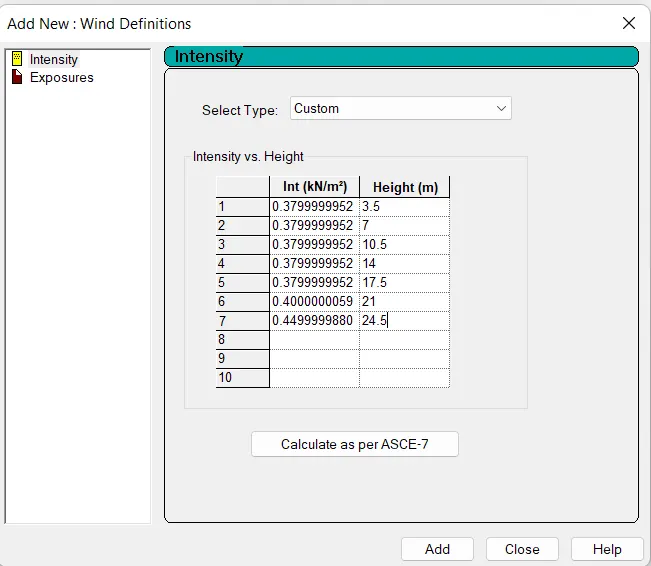
| 3.5 | 1 | 1.05 | 1 | 1 | 34.65 | 720.37 | 0.720 |
| 7 | 1 | 1.05 | 1 | 1 | 34.65 | 720.37 | 0.720 |
| 10.5 | 1 | 1.06 | 1 | 1 | 35.2 | 743.424 | 0.743 |
| 14 | 1 | 1.08 | 1 | 1 | 35.64 | 762.12 | 0.762 |
| 17.5 | 1 | 1.10 | 1 | 1 | 36.3 | 790.61 | 0.790 |
| 21 | 1 | 1.125 | 1 | 1 | 37.13 | 827.18 | 0.827 |
| 24.5 | 1 | 1.13 | 1 | 1 | 37.29 | 834.32 | 0.834 |
| 28 | 1 | 1.15 | 1 | 1 | 37.95 | 864.121 | 0.864 |
Seismic Load:
(i) Design Base Shear:
Vb = Ah X W.
where,
Ah = Horizontal co-efficient of acceleration.
W = Seismic weight.
As we know that the Ah can be calculated by the below given formula:
So, as the iven location is Banglore,therefore:
- Seismic Zone(Z) = Zone ll (0.10)
- Soil Type(Sa) = Hard Soil.
- Importance Factor = 1 For the Residential building.
- Response Reduction Factor = 5 (MRF).
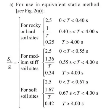
Calculation for Sa/g:
Sa/g = Design Acceleration co-efficient for different soil types.
where, h = Height of the building.
d = Base dimension of the building at the plinth level along the consideration direction of earthquake shaking,in m.
Along X-direction:
Along Z-direction:
Consider the Max. time period = 0.68 secs.
According to the IS code for Hard soil whose T value will be inbetween 0.40 sec to 4.00 sec then the value for Sa/g is 1.47.
Therefore,
R = Reduction Factor.
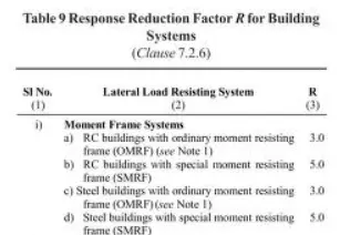
Therefore, R = 5.0
I = Importance Factor.
I = 1
And now out all these values in the Lateral shear formula:=9%">
`Ah= 0.0147.
(b) Seismic weight of building:
(i) Dead and Live Load calculations For all Floors:
Area of each floor = 16 X 25.
= 400 sq.m.
(ll) Typical floor weight due to dead loads,DL = 8.75 Kn/sq.m.
So, total dead load of all floors = 8.75 X 400.
= 3500 KN.
(lll) Due to dead loads,Roof load,RL = 5.25 Kn/sq.m.
So.total dead load of all floors = 5.25 X 400.
= 2100 KN.
(lV) Due to live loads, Floor load,LL =3 KN/sq.m According to IS 875 Part ll.
But according to the IS 1893:2016 if the live load is greater than the 3 KN/sq.m then we have to reduce the Live Load by 50%.
Therefore reduce it by 50%.
Live Load = 1.5 KN/sq.m
Therefore, Total Live Load for all the floors = 1.5 X 400
= 600 KN.
(V) Live load for roofs. According to the IS code 1875:2016 Live load due to the roof is neglected in calculation of the seismic weight.
(Vl) Total Seismic Weight,W=DL+LL+DL of Roof
= (3500+600)X7+2100.
= 30800 KN.
Design Base Shear (Vb) = Ah X W.
where Ah = 0.0147
W = 30800 KN.
Design Base Shear (Vb) = 0.0147 X 30800.
Design Base Shear (Vb) = 452.76 KN
Lateral Force at Different Levels:
Below is the formula to calculate the lateral force at different levels according to the IS code 1893:
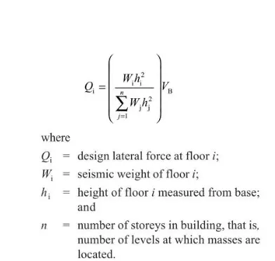
| Storey Level | Wi | hi | Wihi^2 | Ki | Lateral force,Qx | Lateral Force,Qz |
| Roof | 2100 | 28 | 3214400 | 0.31 | 140.035 | 140.035 |
| Sixth Floor | 4100 | 24.5 | 2461025 | 0.24 | 108.66 | 108.66 |
| Fifth Floor | 4100 | 21 | 1808100 | 0.17 | 76.96 | 76.96 |
| Fourth Floor | 4100 | 17.5 | 1255625 | 0.12 | 54.33 | 54.33 |
| Third Floor | 4100 | 14 | 803600 | 0.07 | 31.70 | 31.70 |
| Second Floor | 4100 | 10.5 | 452025 | 0.044 | 19.92 | 19.92 |
| First Floor | 4100 | 7 | 200900 | 0.019 | 8.60 | 8.60 |
| Ground Floor | 4100 | 3.5 | 50225 | 0.005 | 2.26 | 2.26 |
| Total | 102459001 | 442.47 | 442.47 |
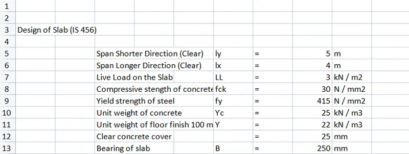
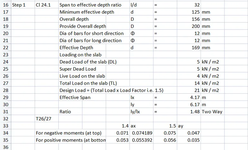
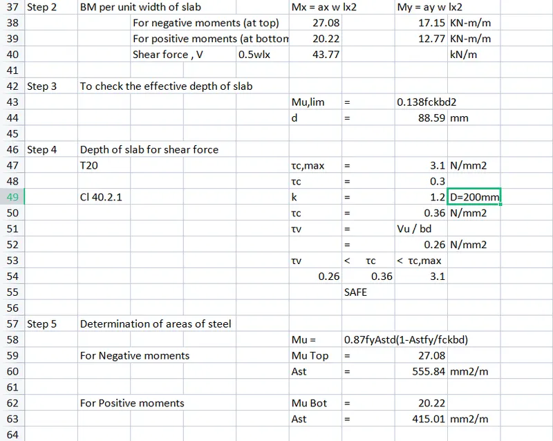
Design slab element using MS – Excel:
Create structural model using STAAD Pro Connect Edition
- First we need to model the building frame according to the Architectural layout and the data given above.
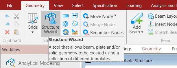
- So in order to model the building frame first we need to open the STAAD Pro software. Create a new file and then open the file after that there will be an option called structure wizard just click on that option in order to create the model frame just as shown in the below given image:
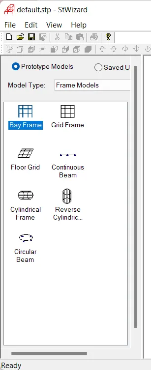
- After clicking on the structure wizard then there will be another dialouge box in that dialouge box there will be another option called default.stp - StWizard in that dialouge box there will be an option called Model type in that select Frame models and in that select the Bay frame option and change the desired units just as shown in the below given image:
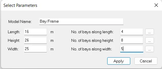
- After that just drag the bay frame int the space and then there will be another dialouge box named as the select parameters in that dialouge box fill out the all necessary data just as shown in the below given image:
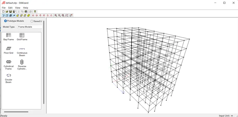
- After that click on the option apply after clicking on the apply option the model frame has been created just as shown in the below given image:
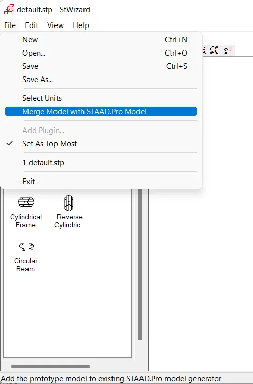
- After this merge this model into the staad pro model just as shown in the below given image:
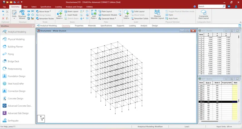
- Frame will be generated automatically after merging the model into the STAAD Pro model just as shown in the below given image:
- After generating the model frame now we will be assigning the material and the section properties which is going to be used in the model.
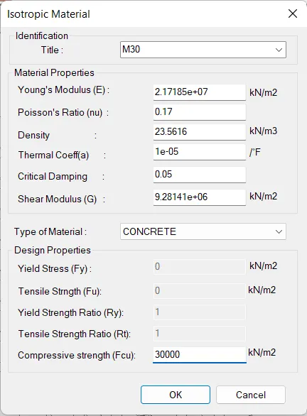
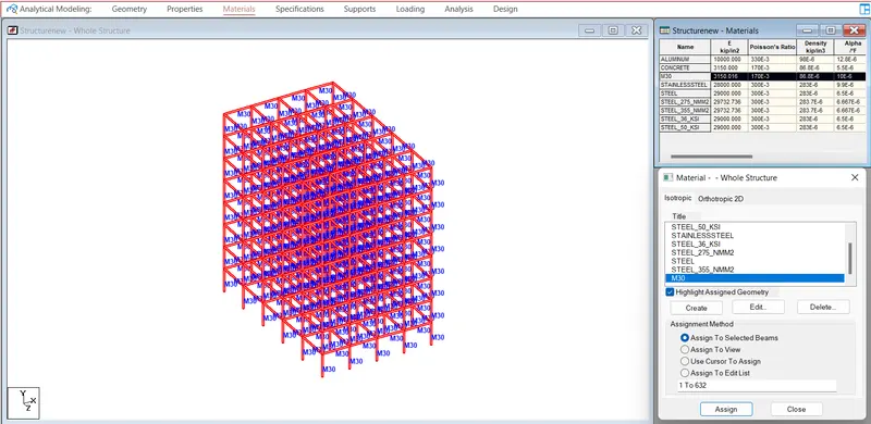
- So on order to create the materials go to the material option add the and then select the material here i am selectiong concrete as the material which is going to be used in the given model.And then specify the compressive strength of the concrete as M30 and the click on the OK option just as shown in the below given image:
- And then assign it to the view just as shown in the below given image:
- Now after that go to the properties option just go to the add define option then there will be another dialouge box named as the property in that dialouge box fill out the necessary option for the beams and click on the add option just as shown in the below given image:
- Now do the same procedure for the columns and fill out the necessary details just as shown in the below given image:
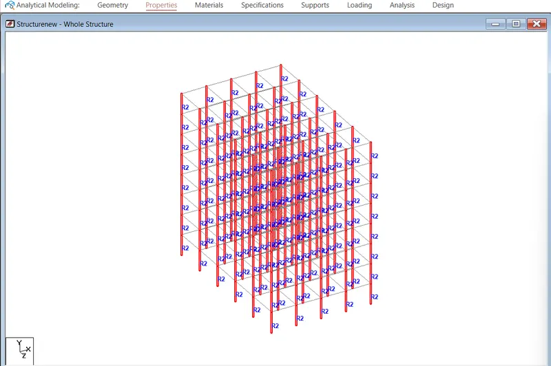
- And then assign it to the columns and the beams. In order to assign it to the column just select the parallel to the Y and then assign it to the column to the selected sections just as shown in the below given image:
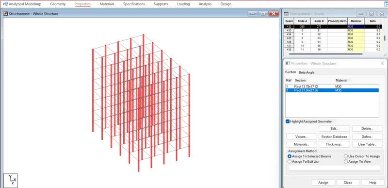
- The columns have been assigned to the selected columns just as shown in the below given image:
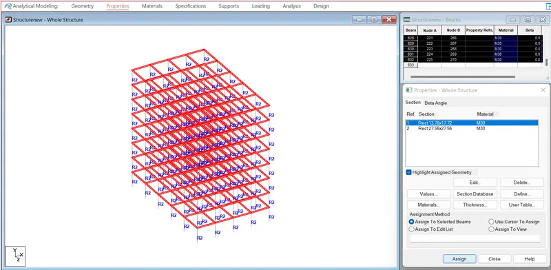
- And now in order to assign the beams select parallel to X and Z and assign it to the beams to the selected sections just as shown in the below given image:
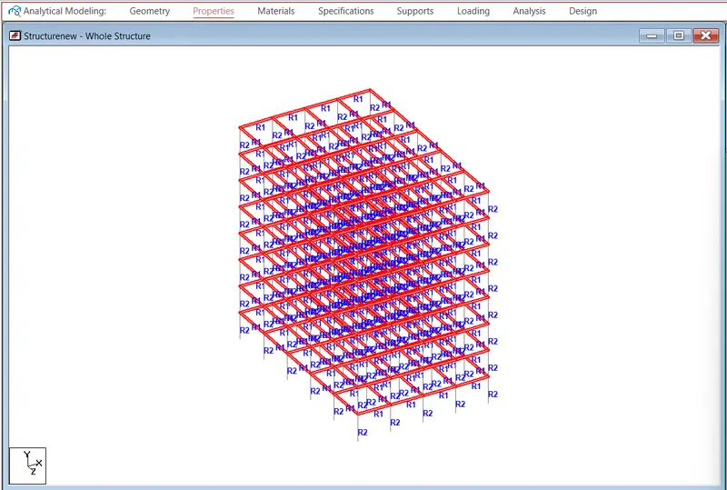
- And now assign it to the selected beams just as shown in the below given image:
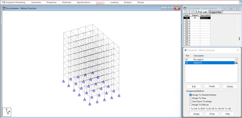
- After this now we will be adding the supports to the model frame so in order to assign the support we need to go to the elevation view select all the nodes of the base level and then assingn the fixed support after adding it to the support pannel.
- Just go to the supports option select the fixed support and then click on the option assign to the selected view just as shown in the below given image:
- And after that check the model in the 3D rendered view in order to check any errors just as shown in the below given image:
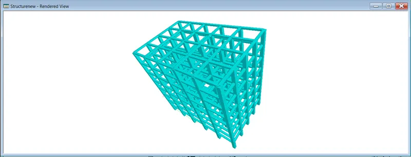
- Now we will be assigning the loads applications.
- Dead Load.
- Live Load.
- Wind Load.
- Seismic Load.
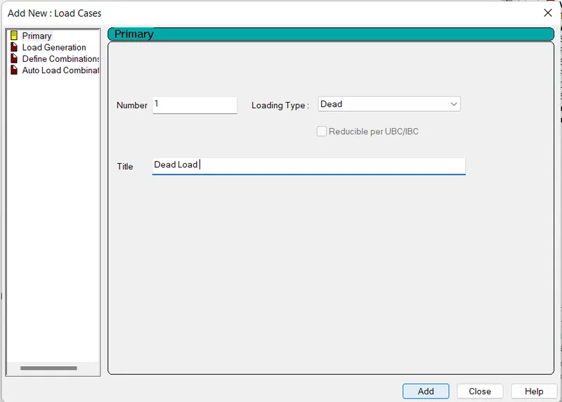
- In order to define and assign the dead load case for self weight,go to the loads tab in that tab there will be an option called Load case details click on that option and thn click on the Add option,after clicking on that option there will be another dialouge box named as the Add New:Load Cases in that dialouge box add the Load case as Dead Load and give the tittle as Dead Load and then click on the option Add and then close just as shown in the below given image:
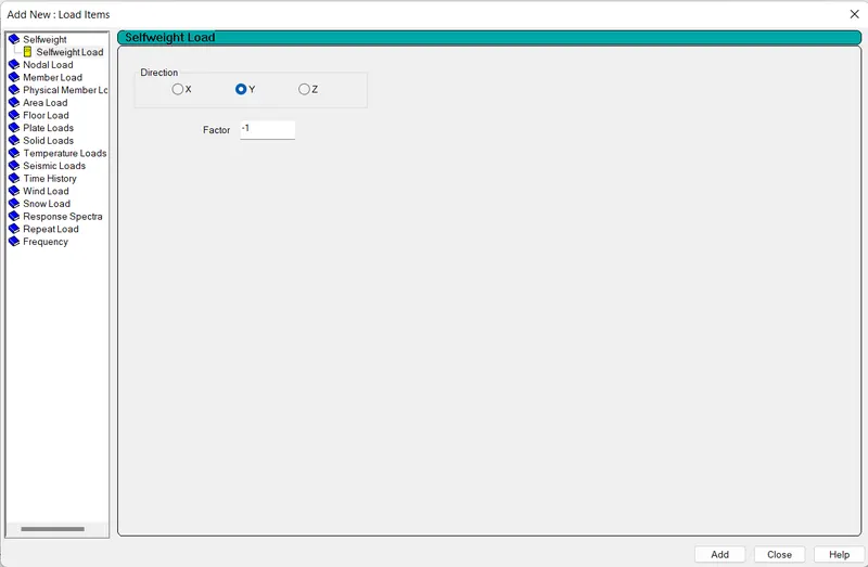
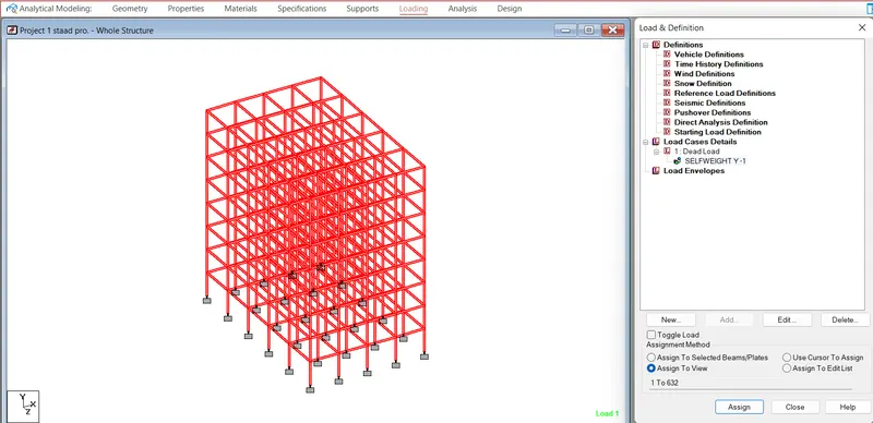
- And after adding the self weight now assigned it to the view just as shown in the below given image:
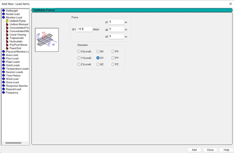
- And now define and assign the superimposed brickwall load for the typical floors,in order to do that first we need to go to the Load case detail here click on the add option then there will be another dialouge box named as the Add Loads:Load Items in that dialouge box go to the option member load and then go to the option Uniform force and put all the necessary details just as shown in the below given image:
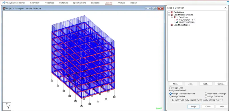
- And then assign the load to the selected beams just as shown in the below given image:
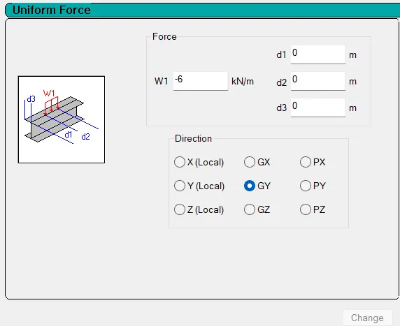
- After this we will be defining and assigning the superimposed roof load in order to add the roof load repeat the same procedure and add the roof load just as shown in the below given image:
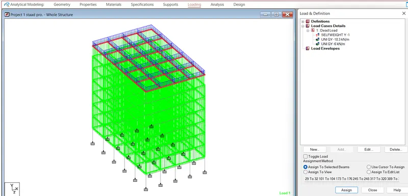
- And then assign it to the selected beams just as shown in the below given image:
- And now we will be adding the floor load in order to do that go to the load case detail and click on the add option and then there will be another dialouge box named as the Add New:Load Items and fill all the necessary details just as shown in the below given image:
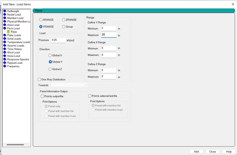
- And then assign it to the given view just as shown in the below given image:
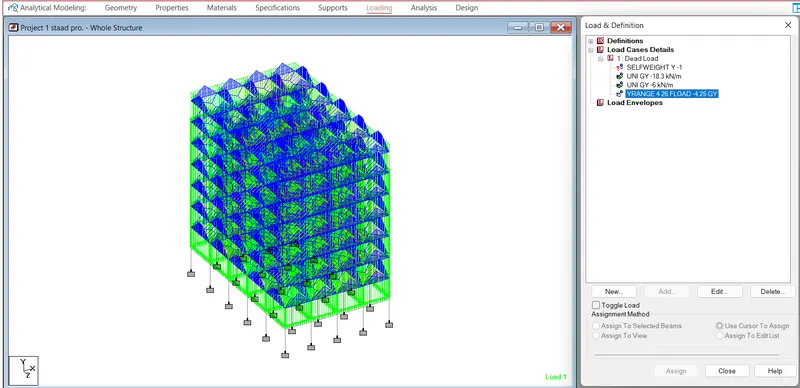
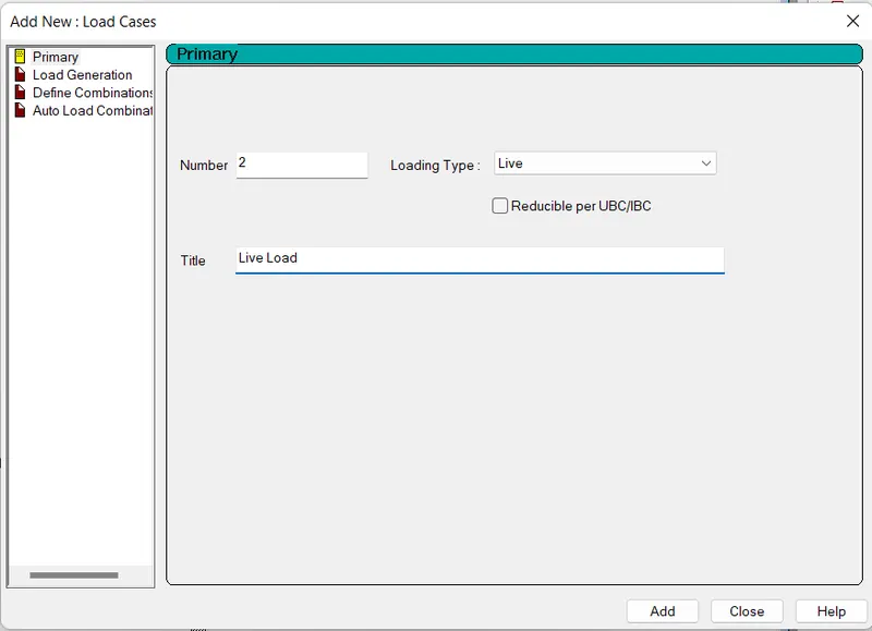
- All the dead loads have been defined and assigned now we have to assign and define the Live Load,so in that case first we need to go to the Load Case detail just click on that option after that click on the option Add and then there will be another dialouge box named as the Add New:Load Cases and give the loading type as Live and tittle as the Live Load and then click on the option add and close just as shown in the below given image:
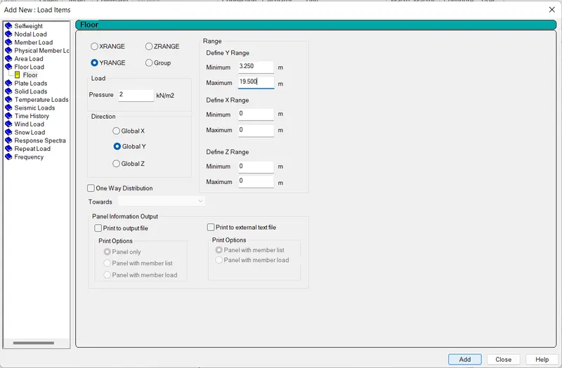
- Now give the live load to the typical floors according to the IS code 875. So in order to do that first go to the option Live Load and then click on the option add and then there will be another dialouge box named as the Add New:Load Items in that there is an option floor load just click on that option and then fill out the necessary information and then click on the add option and then close just as shown in the below given image:
- And then assign it to the selected beams just as shown in the below given image:
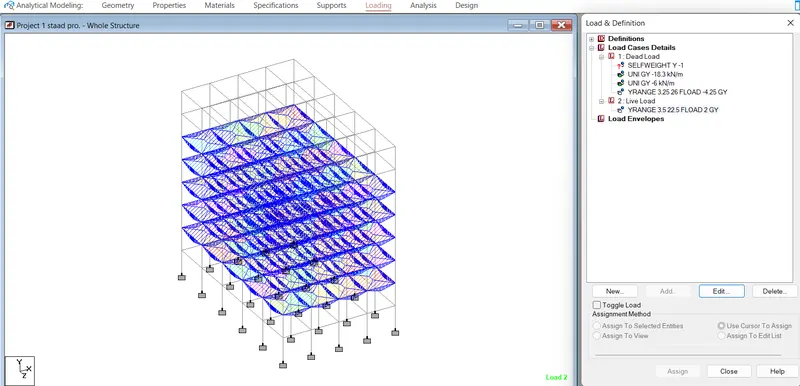
- And now we will be adding the roof load just as shown in the below given image:
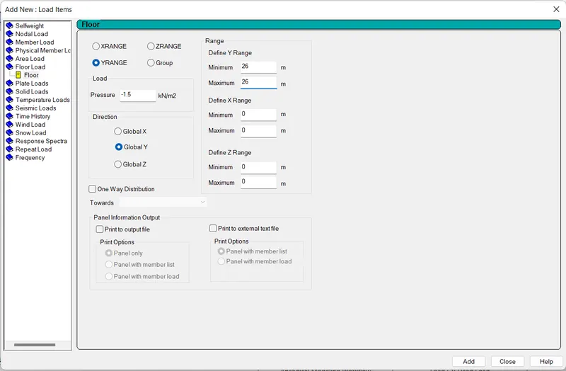
- And now assign it to the view just as shown in the below given image:
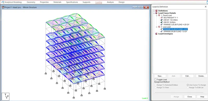
- And now we will be adding the seismic loadings to the frame,in order to do that click on the option load case detail and then click on the add option and add the seismic load just as shown in the below given image:
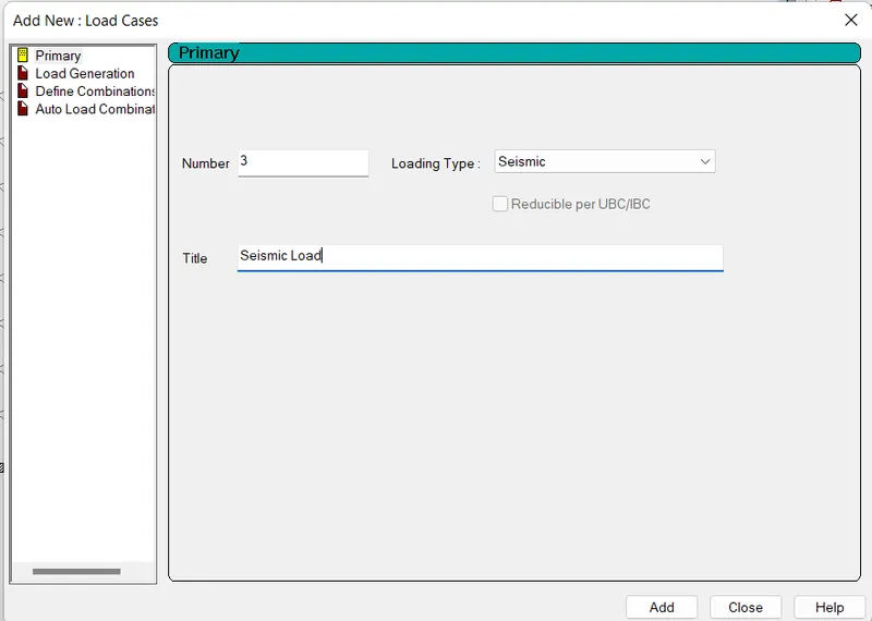
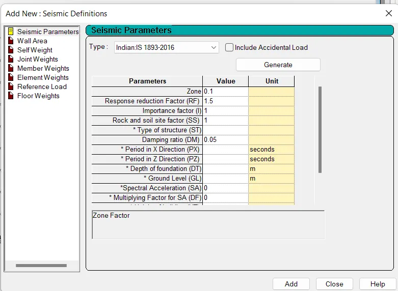
- In order to add the siesmic load first we need to go to the seismic defination option click on that option after that there will be another dialouge box named as the Add New:Seismic Definitions,in that dialouge box there is an option type in that box choose the IS code as IS 1893:2016 and there will be another option called Generate click on that option just as shown in the below given image:
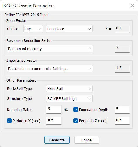
- After clicking on the option Generate there will be another dialouge box named as the IS:1893 Seismic Parameters, in that dialouge box fill out the information just as shown in the below given image:
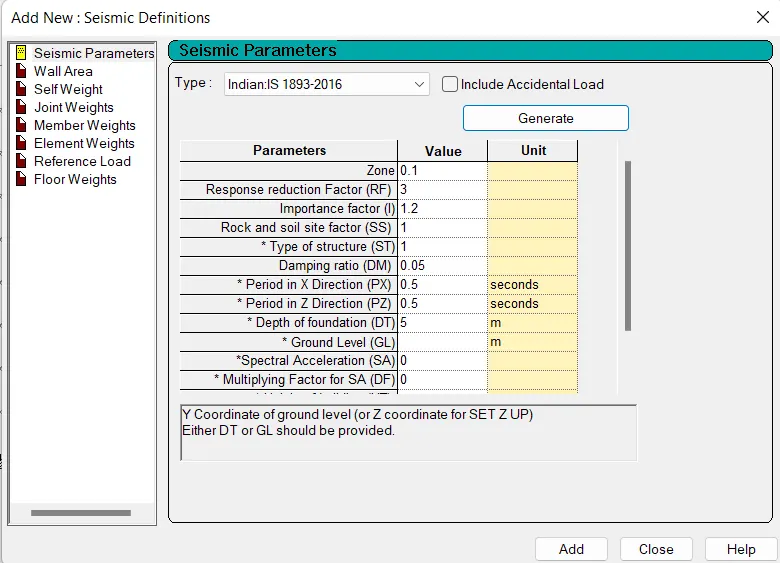
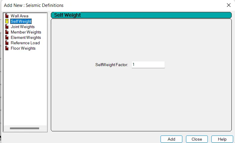
- And now after this we will be adding the seismic self weight of the building just as shown in the below given image:
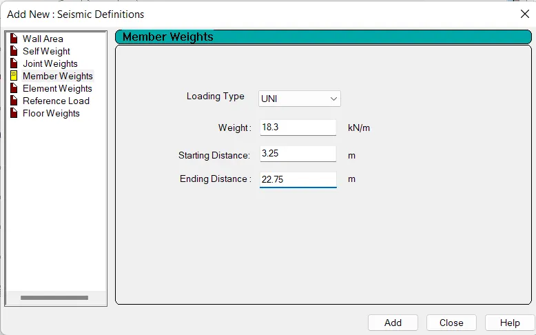
- Now add the member weight for the floors just as shown in the below given image:
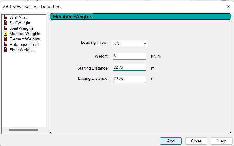
- Now add the member weight for the roof slab just as shown in the below given image:
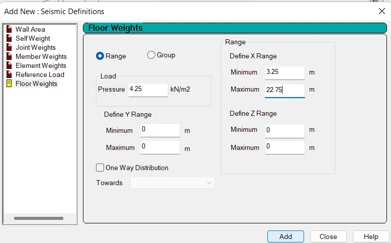
- And after this we will be adding the floor weight just as shown in the below given image:
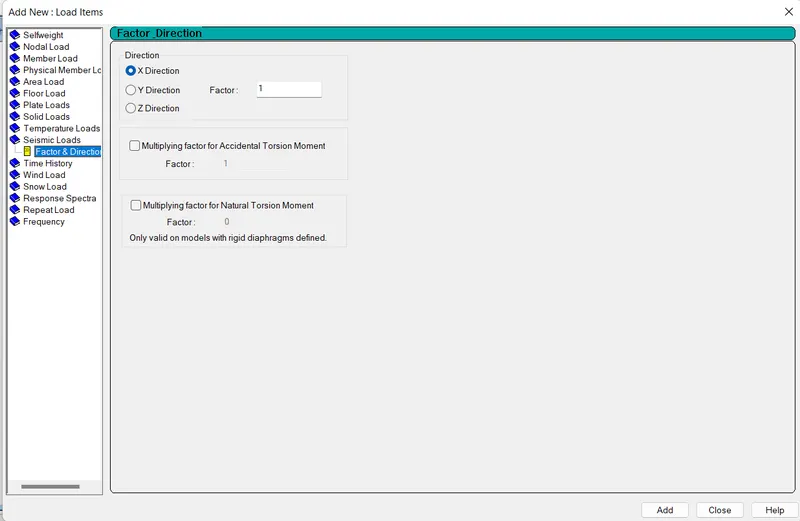
- Now add the earthquake load in the X-direction just as shown in the below given image:
- Now add the earthquake load in the Z-direction just as shown in the below given image:
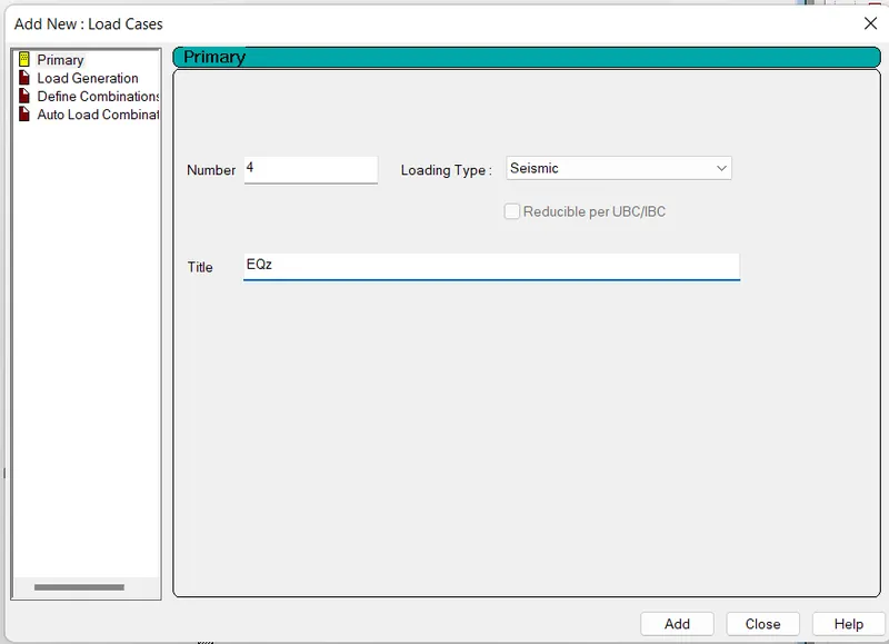
- After that we will be defining he wind load in order to define and assign the wind load go to the load case detail option click on the add option and add a new load named as the Wind Load just as shown in the below given image:
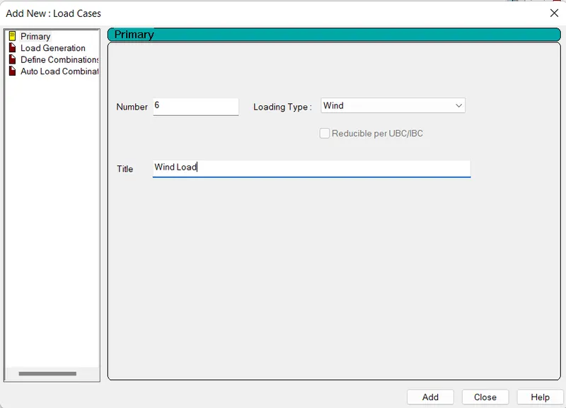
- Now add the wind load according to the Calculation in accordance with the IS 875(Part-III) just as shown in the below given image:
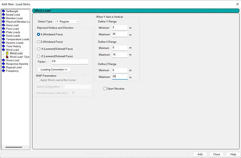
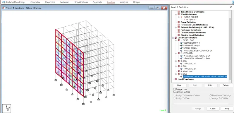
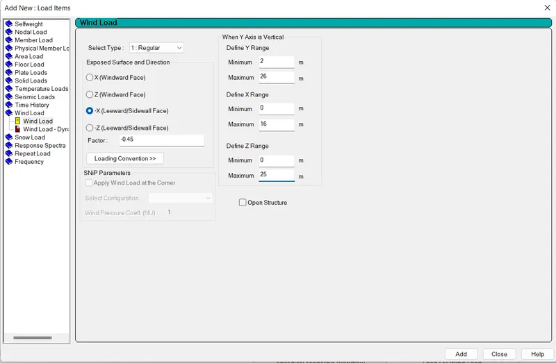
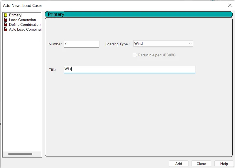
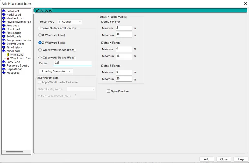
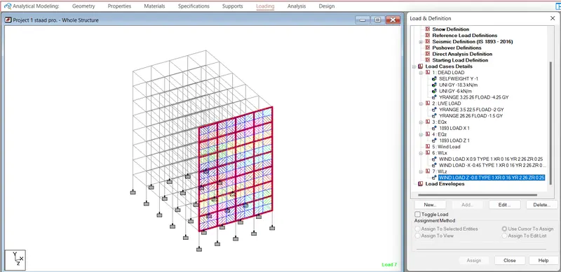
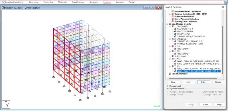
- Now add the wind case in the X-direction,add the wind factor in the both direction i.e,winndward and leeward direction just as shown in the below given image:
X-Windward:
X-Leeward:
Z-Windward:
Z-Leeward:
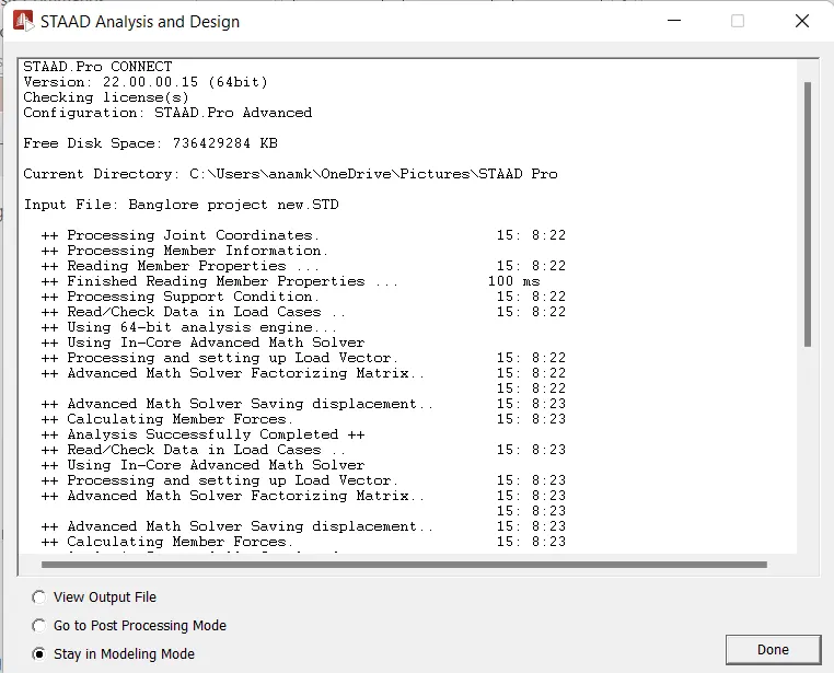
- And now that all the loads have been applied here successfully to the building and now add the analysis command and run the analysis just as shown in the below given image:
Prepare DL, LL, WL and EQL load calculations as per IS 875 standards:
- And now after doing the analysis of the model,we will be designing the Beams first using the Advance Concrete Designer (RCDC).
Design beam and column element using STAAD RCDC. Attach the design calculation report.
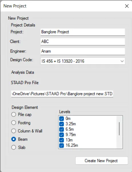
- So in order to design the beams using the RCDC,go to the designing tab there will be an option called RCDC just click on that option and then there will be a new window of RCDC opens in that window fill out the necessary information and click on the Create New Project opion just as shown in the below given image:
- After clicking on the Create New Project it will take some time to analyse all the structural elements after analysing the elements there will be another window of the new project that we just created it shows the beams details just as shown in the below given image:
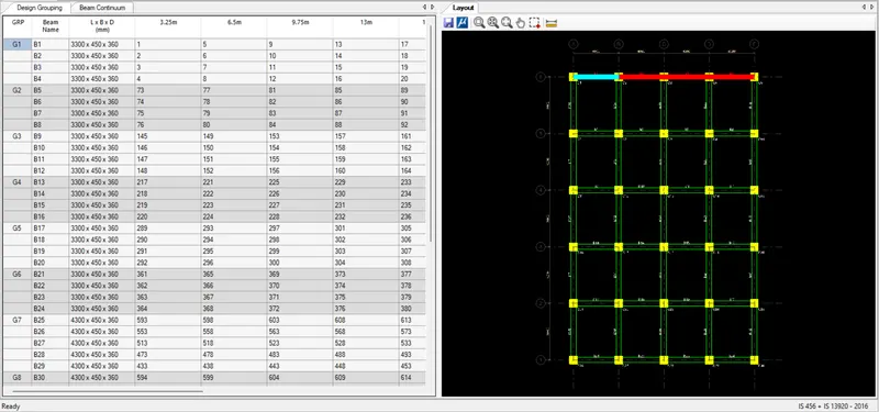
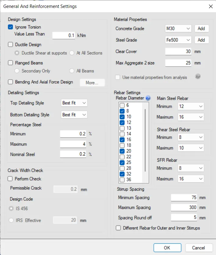
- After this go to the Setting tab then there will be a drop down list in that list there will be an option called General and Reinforcement just click on that option,after clicking that option there will be another dialouge box named as the General and Reinforcement Settings in that dialouge box fill the data just as shown in the below given image:
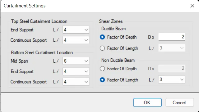
- Now again go to the Setting tab click on that again there will be a drop-down list in that list there will be another option called Rebar Curtailment,after clicking on that option there will be another dialouge box named as the Curtailment settings,in that dialouge box fill out the necessary data and click on the OK option just as shown in the below given image:
- After the curtailment settings now acquire all the loads and the load combinations,just as shown in the below given image:
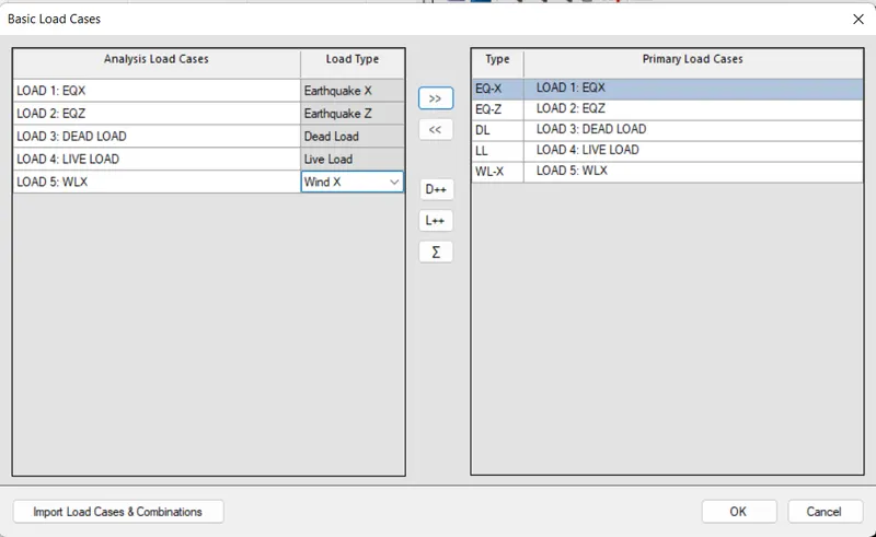
- Now import the load combinations also just as shown in the below given image:
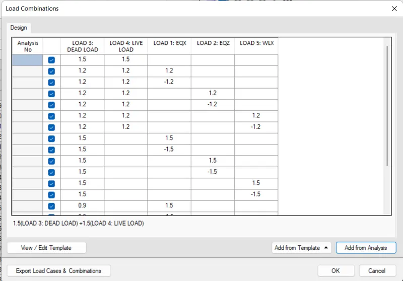
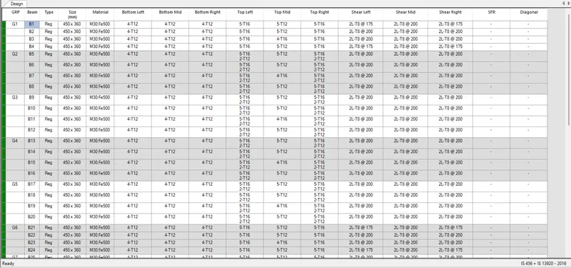
- Now Run the automated design,in order to do that go to the Design option then there will be a drop-down list in that list there will be an option called Auto-design just click on that option and then wait for few minutes the auto generated report is shown below :
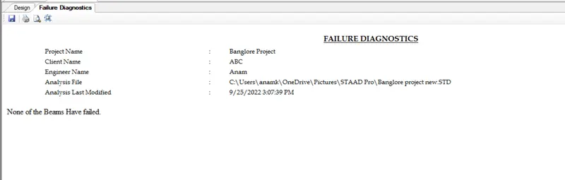
- After this run the failure diagnosis in order to check if all the members have passed or not,so in order to do that go to the option Reports click on that option after that there will be a drop-down list in that list there will be an option called Failure Diagnosis just click on that,it will create the failure diagnosis just as shown in the below given image:
- And now we will be generating the reinforcement detailing of the beam,so in order to do that just go to the report option then there will be a drop-down list in that list there will be an option called Elevation just click on that option after that there will be another dialouge box named as the Select Beam in that dialouge box select the desired beam in which we want to see the reinforcement detailing,select the beam and click on the OK option just as shown in the below given image:
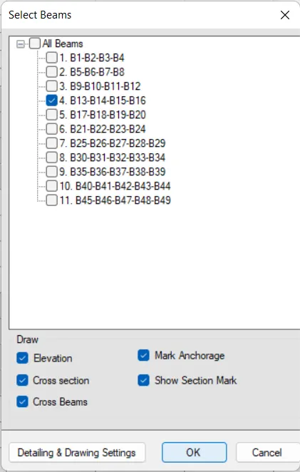
Reinforcement Detail of beam B13,B14,B15 and B16 are given below:
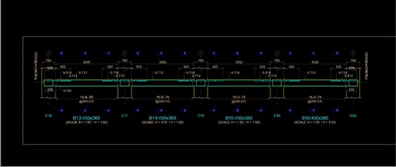
B13:
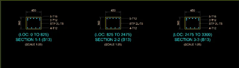
B14:
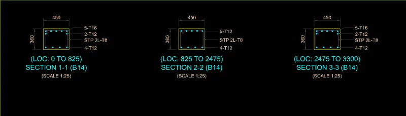
B15:
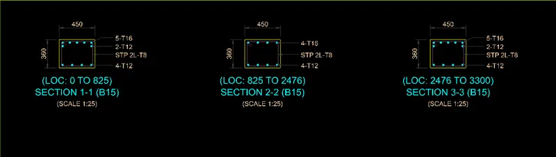
B16:
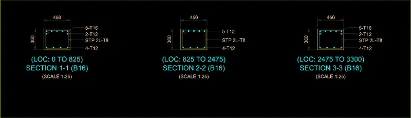
Calculation Sheet:
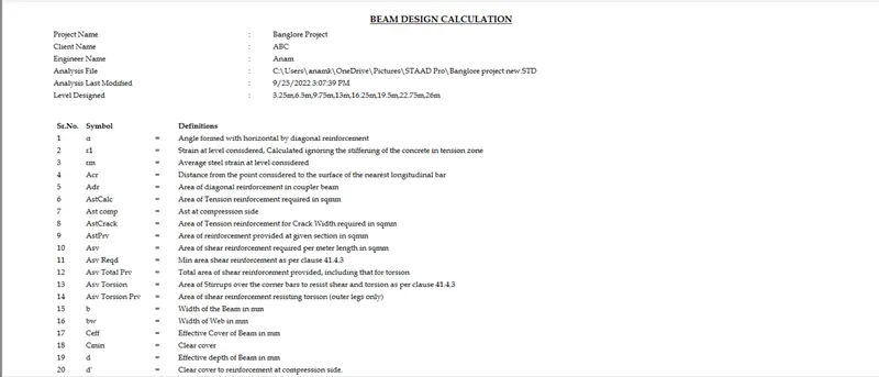
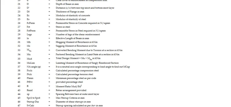
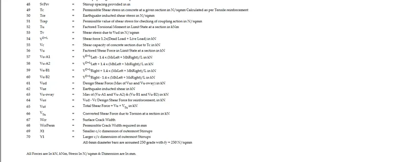
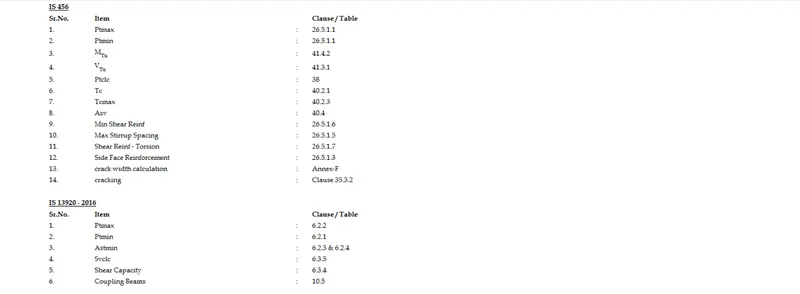
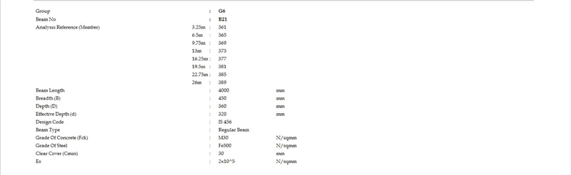
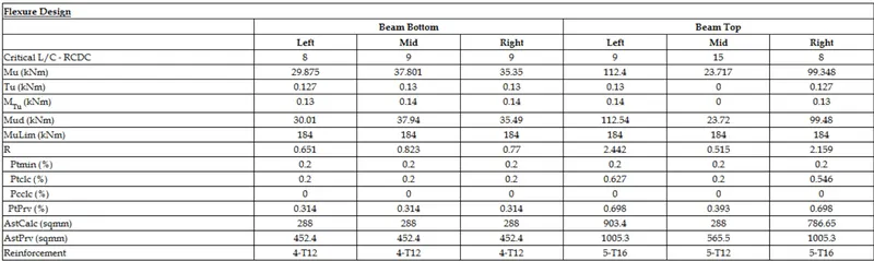
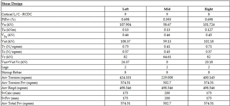
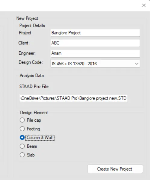
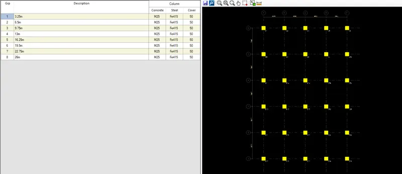
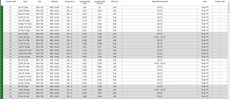
- And now we are going to design the column in the same manner as the beam designing.
- Create the project and wait for few seconds just as shown in the below given image:
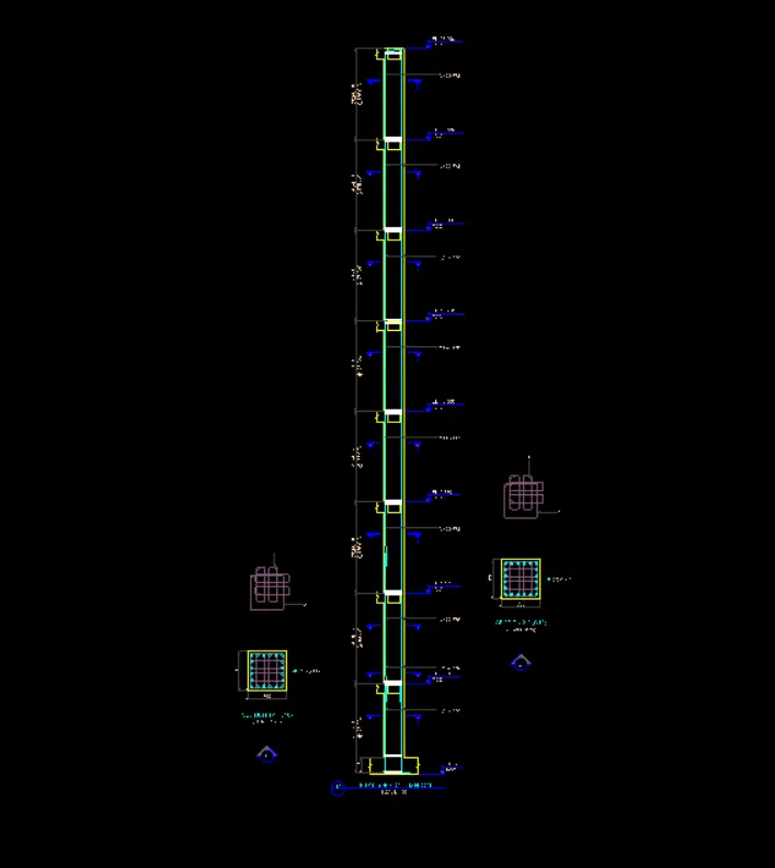
Elevation and section of the column:
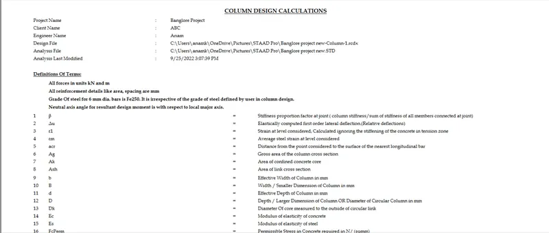
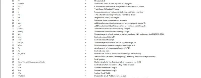
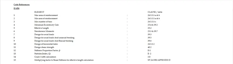
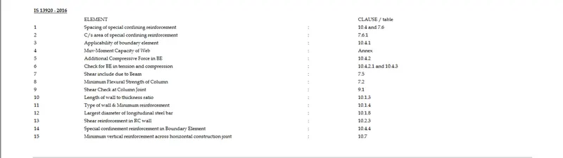
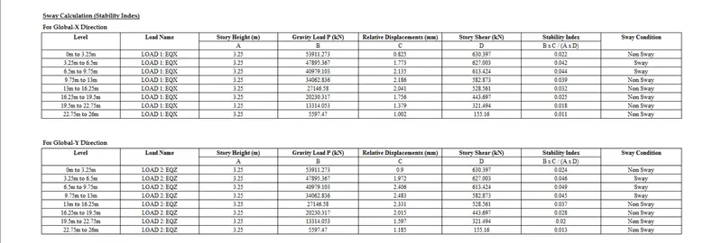
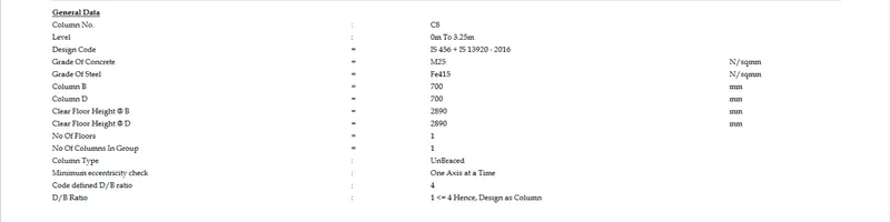
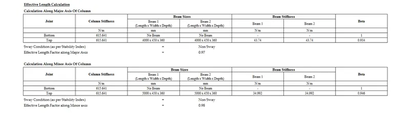
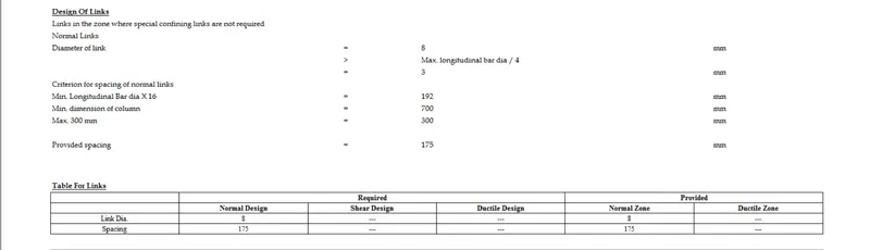
Design Calculation Report:

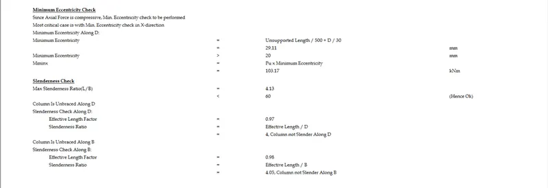
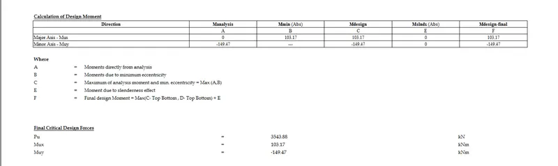

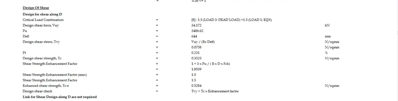
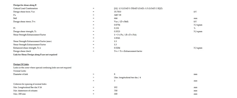
Design Foundations using STAAD Foundation.
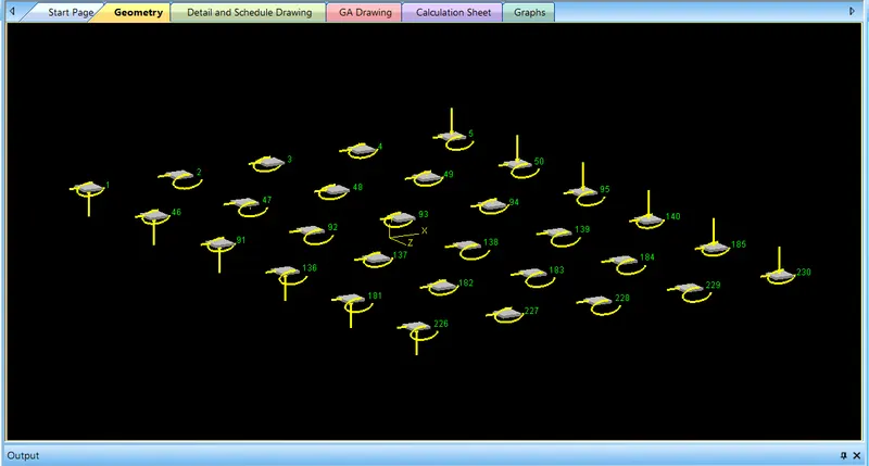
- First of all import the file into the STAAD Pro Foundation and then define the basic information like the general information,scale things etc which is related to the foundation.
-Now after setting the basic information regarding the foundation,now we need to go to the loading and factors options,in that option we will be able to find the basic laodings and the load combinations.
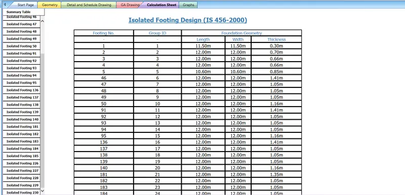
Design Output :
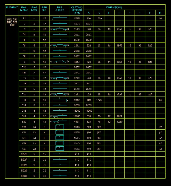
Prepare bar bending schedule for beam and column using STAAD RCDC.
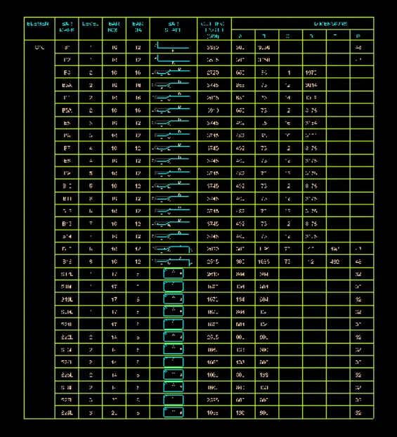
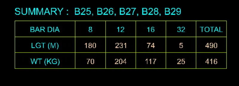
Bar Bending Schedule for Beam:
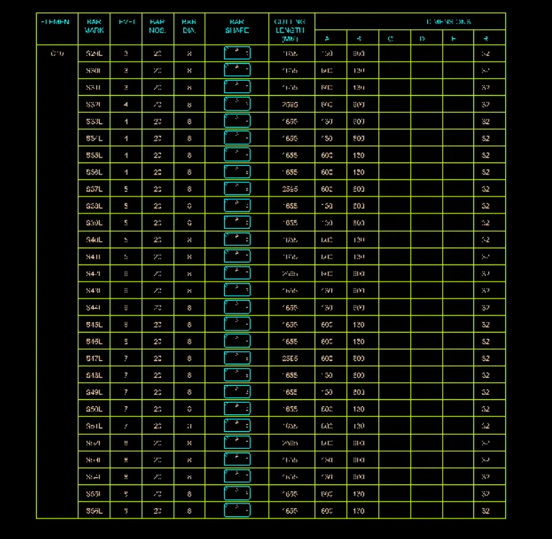
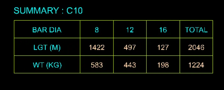
Bar Bending Schedule for Column: