Drafting of various geometries using Chamfer, Fillet tool in AutoCad
Figure 01
- AIM :
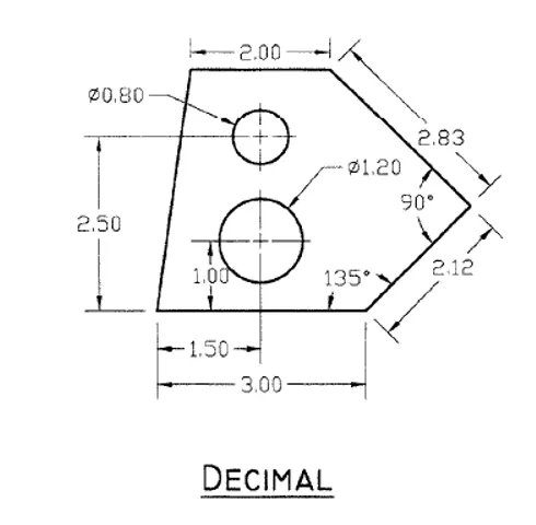
To draw the following figure using in Autocad.
- Introduction:Geometric modeling: concerned with the computer compatible mathematical description of the geometry of an object. The mathematical description allows the image of an object to be displayed and manipulated on a graphics terminal through signals from the CPU of the CAD system. The software that provides geometric modeling capabilities must be designed for efficient use both by computer and the human designer.
- Commands used:
- Line
- circle
- Dimension style
- Procedure:
- New sheet- units- decimal-precision 0.00- meter-ok.
- Limits- 0,0 and 1000,1000.
- zoom-All.
- Select Line tool and draw the lengths starting from base of 3.00 units , now give line command @2.12<45, @2.83<135, @2.00<180, and close.
- Draw the first circle at x=1.50 and y=1.00 of diameter 1.20 units. Similarly, draw another circle at x=1.50 and y=2.50 of diameter 0.80 units.
- Annotate and give dimension to all the line segments and circles.
- Results :
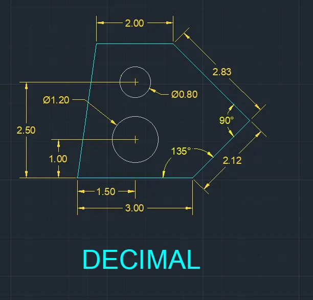
Figure 02
- AIM :
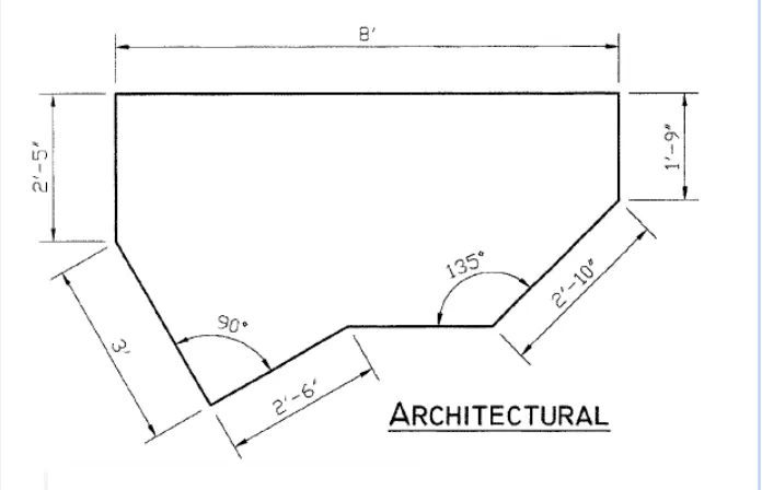
To draw the following figure using in Autocad.
- Introduction:Geometric modeling: concerned with the computer compatible mathematical description of the geometry of an object. The mathematical description allows the image of an object to be displayed and manipulated on a graphics terminal through signals from the CPU of the CAD system. The software that provides geometric modeling capabilities must be designed for efficient use both by computer and the human designer.
- Commands used:
- line
- Dimension style
- Procedure:
- New sheet- units- architectural-precision 0'-0"- feet-ok.
- Limits- 0'-0",0'-0"and 12"-0",9'-0".
- zoom-All.
- Select Line tool and draw the lengths starting from top line segment of 2'-6.5" , now give line command positioning the cursor downwards with ortho ON , 3'-3.0", 5'-0.1",1'-6.0" and close.
- Annotate and give dimension to all the line segments.
- Results :
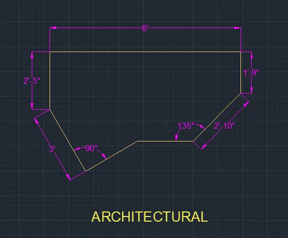
Figure 03
- AIM :
To draw the following figure using in Autocad.
- Introduction:Geometric modeling: concerned with the computer compatible mathematical description of the geometry of an object. The mathematical description allows the image of an object to be displayed and manipulated on a graphics terminal through signals from the CPU of the CAD system. The software that provides geometric modeling capabilities must be designed for efficient use both by computer and the human designer.
- Commands used:
- Line.
- Circle.
- Chamfer
- Dimention style
- trim
- Procedure:
1.New sheet- units- architectural-precision 0'-0"- feet-ok.
2.Limits- 0'-0",0'-0"and 12"-0",9'-0".
3. zoom-All.
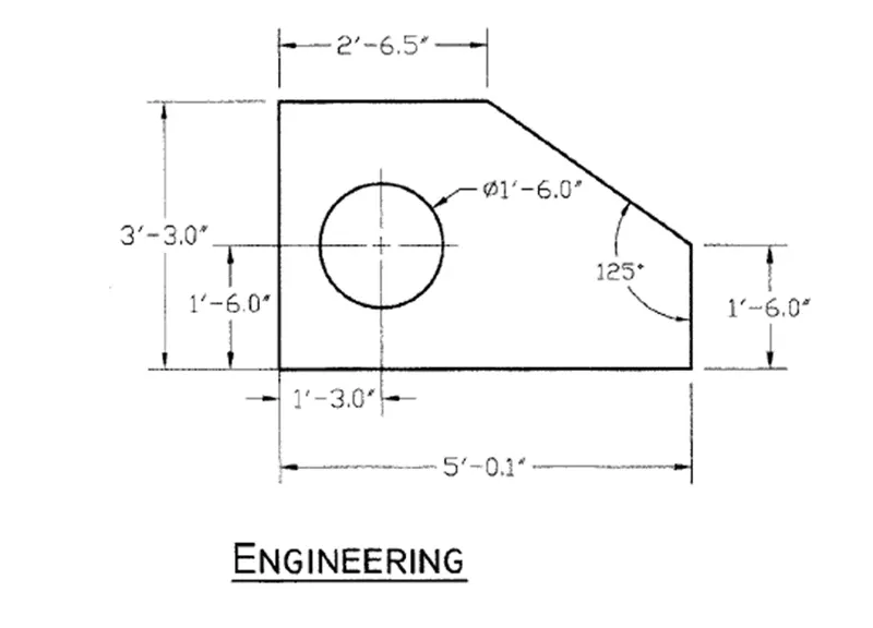
4. Select Line tool and draw the lengths starting from top line segment of 2'-6.5" , now give line command positioning the cursor downwards with ortho ON , 3'-3.0", 5'-0.1",1'-6.0" and close.
5.Annotate and give dimension to all the line segments.
- Results :
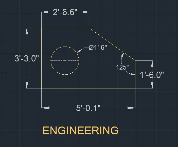
Figure 04
- AIM :
To draw the following figure using in Autocad.
- Introduction:Geometric modeling: concerned with the computer compatible mathematical description of the geometry of an object. The mathematical description allows the image of an object to be displayed and manipulated on a graphics terminal through signals from the CPU of the CAD system. The software that provides geometric modeling capabilities must be designed for efficient use both by computer and the human designer.
- Commands used:
- Circle.
- Chamfer
- Dimention style
- trim
- Procedure:
1.New sheet- units- decimal-precision 0.0000- meter-ok.
2.Limits- 0,0 and 420,210.
3. zoom-All.
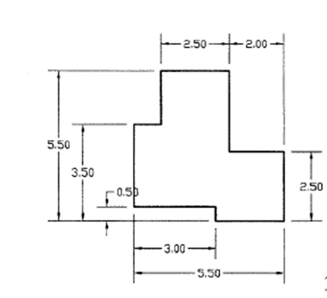
4. Select Line tool and draw the lengths starting from base of 2.5000 units , now give line command @2<270, @0.5<180, @3.00<270, @3<0,@0.5<270, @2.5<0, @2.5<90,@2<180 and close.
5.Annotate and give dimension to all the line segments and circles.
- Results :
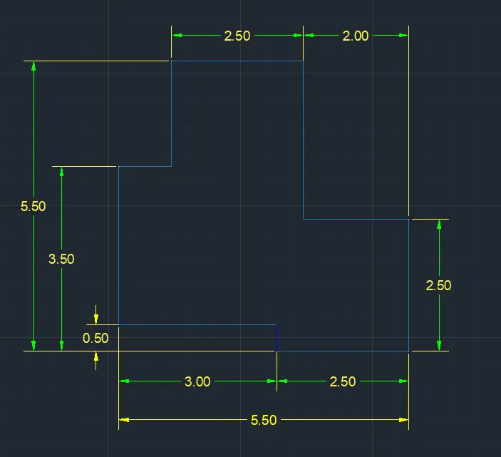
Figure 05
- AIM :
To draw the following figure using in Autocad.
- Introduction:Geometric modeling: concerned with the computer compatible mathematical description of the geometry of an object. The mathematical description allows the image of an object to be displayed and manipulated on a graphics terminal through signals from the CPU of the CAD system. The software that provides geometric modeling capabilities must be designed for efficient use both by computer and the human designer.
- Commands used:
- Line.
- Circle.
- Offset.
- Trim.
- Erase
- Explode.
- Procedure:
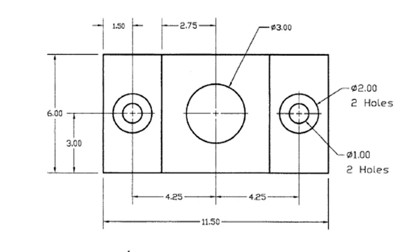
1.New sheet- units- decimal-precision 0.0000- meter-ok.
2.Limits- 0,0 and 420,210.
3. zoom-All.
4. Select Line tool and draw the lengths starting from base of 11.50 units , now give line command @6<90, @11.50<180, and close. Draw the vertical lines at 2.75 from the centre of the rectangle on both sides.
5. Draw concentric circles with centre at x=1.50 and y=3.00 of diameter 1.00 and 2.00 . Copy the circles toward 4.25 right from the of the rectangle.
6. Draw another circle at centre of the rectangle of diameter 3.00.
7.Annotate and give dimension to all the line segments and circles.
- Results :
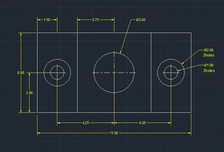
Figure 06
- AIM :
To draw the following figure using in Autocad.
- Introduction:Geometric modeling: concerned with the computer compatible mathematical description of the geometry of an object. The mathematical description allows the image of an object to be displayed and manipulated on a graphics terminal through signals from the CPU of the CAD system. The software that provides geometric modeling capabilities must be designed for efficient use both by computer and the human designer.
- Commands used:
- Line.
- Offset.
- Trim.
- Erase.
- Chamfer.
- Procedure:
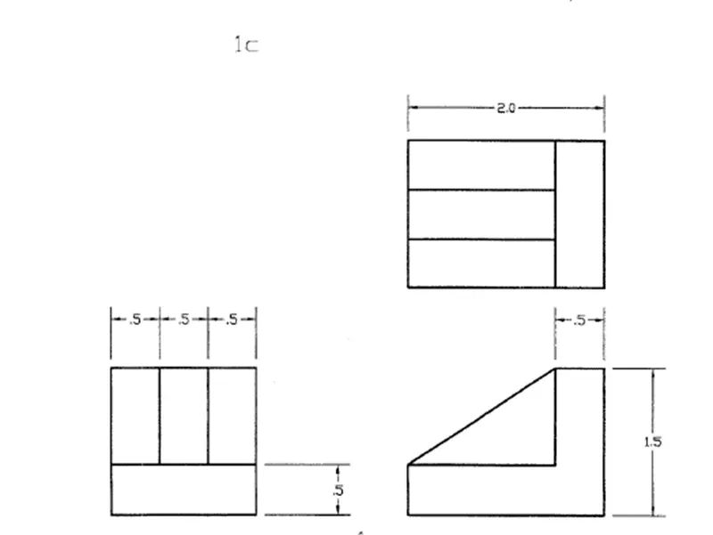
1.New sheet- units- decimal-precision 0.0000- meter-ok.
2.Limits- 0,0 and 420,210.
3. zoom-All.
4. Select Line tool and draw the lengths starting from base of 1.5000 units,Draw offset at 0.5000. Taking the total length 1.5000 doraw an outer boundary and take offset of 0.5000 for the vertical segments. Follow the steps to draw 2.0000 ht geometry anf rotate towards left. Using Line command draw the L shape geomtrey and connect to make the triagular portion.
5.Annotate and give dimension to all the line segments and circles.
- Results :
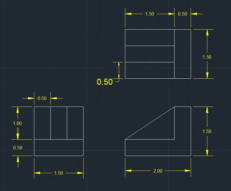
Figure 07
- AIM :
To draw the following figure using in Autocad.
- Introduction:Geometric modeling: concerned with the computer compatible mathematical description of the geometry of an object. The mathematical description allows the image of an object to be displayed and manipulated on a graphics terminal through signals from the CPU of the CAD system. The software that provides geometric modeling capabilities must be designed for efficient use both by computer and the human designer.
- Commands used:
- Line.
- Offset.
- Trim.
- Erase.
- Chamfer.
- Procedure:
1.New sheet- units- decimal-precision 0.0000- meter-ok.
2.Limits- 0,0 and 420,210.
3. zoom-All.
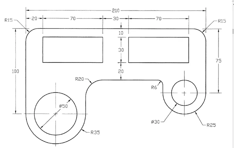
4. Select Line tool and draw the lengths starting from base of 210 units , now give line command @100<270. Draw @75<270. Draw the rectangles 70,30 and copy at distance 30.
5. Draw circles with centre at y=100 and y=75. Draw parallel lines from both the circle and using fillet tool give radius of 35, 20, 6 and 15 .
6.Annotate and give dimension to all the line segments and circles.
- Results :
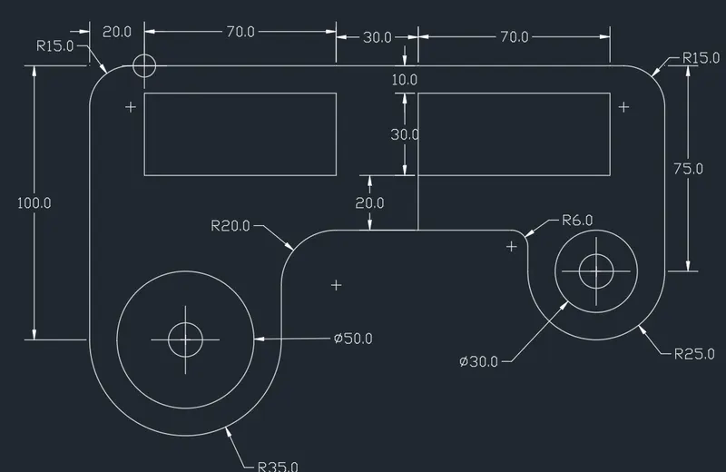
Figure 08
- AIM :
To draw the following figure using in Autocad.
- Introduction:Geometric modeling: concerned with the computer compatible mathematical description of the geometry of an object. The mathematical description allows the image of an object to be displayed and manipulated on a graphics terminal through signals from the CPU of the CAD system. The software that provides geometric modeling capabilities must be designed for efficient use both by computer and the human designer.
- Commands used:
- Line.
- Offset.
- Trim.
- Erase.
- Chamfer.
- Procedure:
1.New sheet- units- decimal-precision 0.0000- meter-ok.
2.Limits- 0,0 and 420,210.
3. zoom-All.
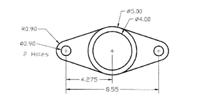
4. Draw concentric circles with diameter 4 and 5 units. Draw one rircle at 4.275 distance from the centre. Draw parallel line and draw a fillet of radius 0.9 and extend the lines todraw the tangent of bigger circle. Mirror the same towards right and trim the extras in geometry.
5.Annotate and give dimension to all the line segments and circles.
- Results :
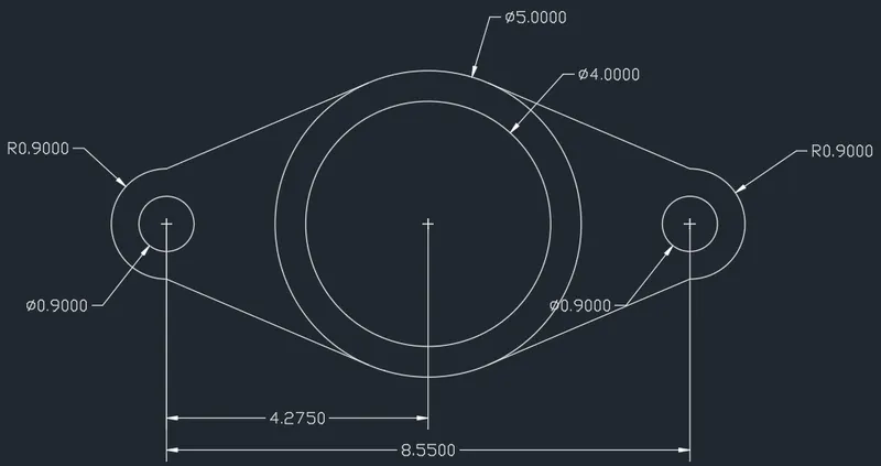
Figure 09
- AIM :
To draw the following figure using in Autocad.
- Introduction:Geometric modeling: concerned with the computer compatible mathematical description of the geometry of an object. The mathematical description allows the image of an object to be displayed and manipulated on a graphics terminal through signals from the CPU of the CAD system. The software that provides geometric modeling capabilities must be designed for efficient use both by computer and the human designer.
- Commands used:
- Line.
- Offset.
- Trim.
- Erase.
- Chamfer.
- Procedure:
1.New sheet- units- architectural-precision 0'-0"- feet-ok.
2.Limits- 0'-0",0'-0"and 12"-0",9'-0".
3. zoom-All.
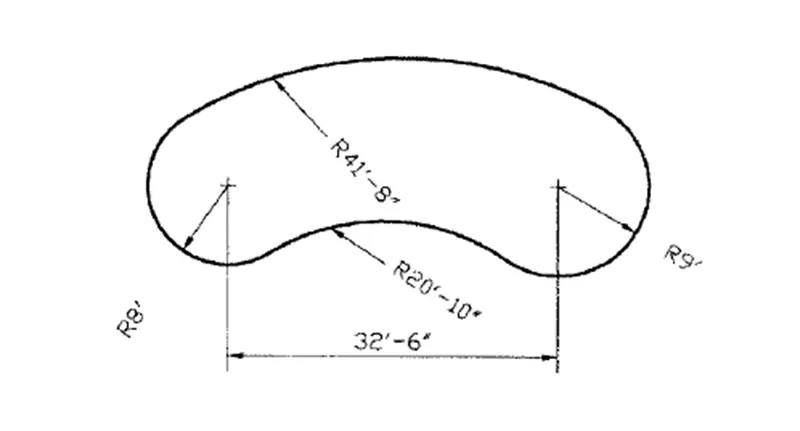
4. Select circle tool and draw the circles of radius 8' and 9' at a centre to centre distance of 32'-6". Using fillet connect the circles with radius 41'-8" and 20'-10".
5.Annotate and give dimension to all the line segments.
- Result :
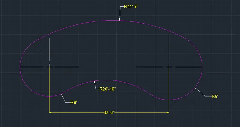
Figure 10
- AIM :
To draw the following figure using in Autocad.
- Introduction:Geometric modeling: concerned with the computer compatible mathematical description of the geometry of an object. The mathematical description allows the image of an object to be displayed and manipulated on a graphics terminal through signals from the CPU of the CAD system. The software that provides geometric modeling capabilities must be designed for efficient use both by computer and the human designer.
- Commands used:
- Line.
- Offset.
- Trim.
- Erase.
- Chamfer.
- Procedure:
-
1.New sheet- units- decimal-precision 0.0000- meter-ok.
2.Limits- 0,0 and 420,210.
3. zoom-All.
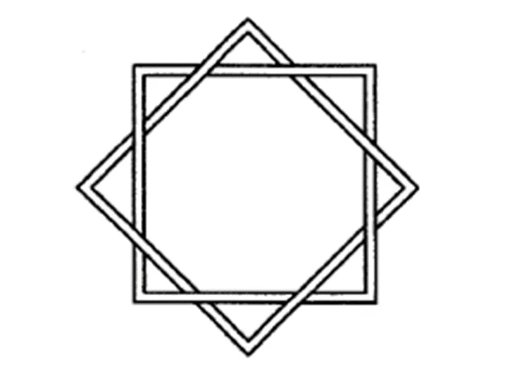
4. Draw square usinf rectangle tool with width 0.2 of equal sides. Copy and rotate at 45 degrees.
5. Move the rotated rhombus over the square and trim the unwanted lines.
- Results :
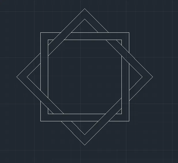
Figure 11
- AIM :
To draw the following figure using in Autocad.
- Introduction:Geometric modeling: concerned with the computer compatible mathematical description of the geometry of an object. The mathematical description allows the image of an object to be displayed and manipulated on a graphics terminal through signals from the CPU of the CAD system. The software that provides geometric modeling capabilities must be designed for efficient use both by computer and the human designer.
- Commands used:
- Line.
- Offset.
- Trim.
- Erase.
- Chamfer.
- Procedure:
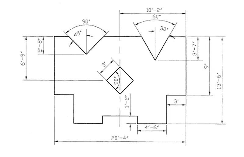
1.New sheet- units- architectural-precision 0'-0"- feet-ok.
2.Limits- 0'-0",0'-0"and 12"-0",9'-0".
3. zoom-All.
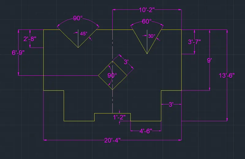
4. Select Line tool and draw the lengths starting from top line segment of 9'-0", changing the position of cursor in direction of the line with ortho On draw 3'-0", 4'-6",4'-6",1'-2". Now. take copy and mirror the left to right and join to close. Draw a square of side 3'-0" and rotate to 45 degrees and position it using move tool. Using ling line tool draw vertical lines of 2'-8" and 3'-7" and make 30 degrees line on each side with respect to reference vertical line and 60 degrees on the othe end.
5.Annotate and give dimension to all the line segments.
- Results :