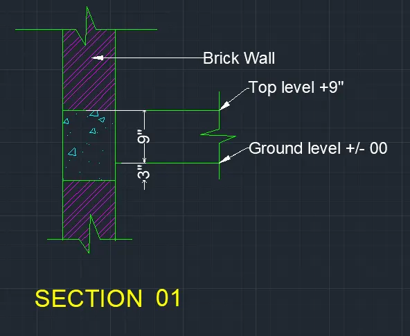
Creation of Column Schedule and Drawing Template using AutoCad
Figure : 01
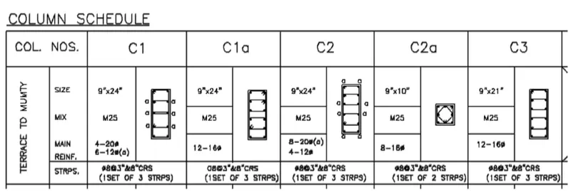
AIM: To Create a column schedule as shown in the figure:
Introduction :
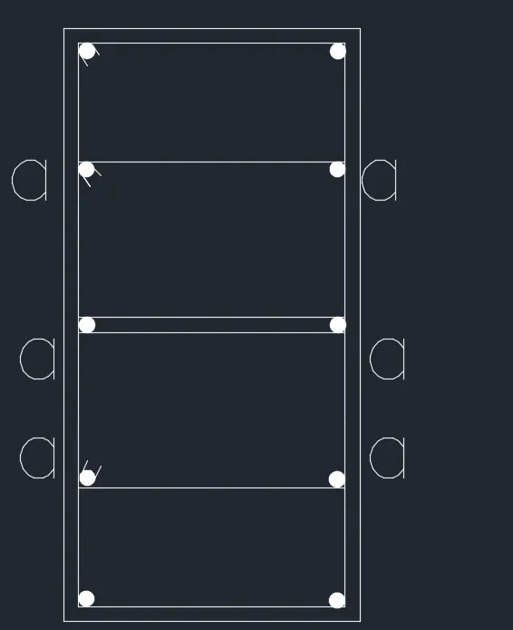
- Column C1 is provided with 4 bars of 20 mm dia. and 6 bars of 12 mm dia. The 12 mm dia bars are marked with 'a'.
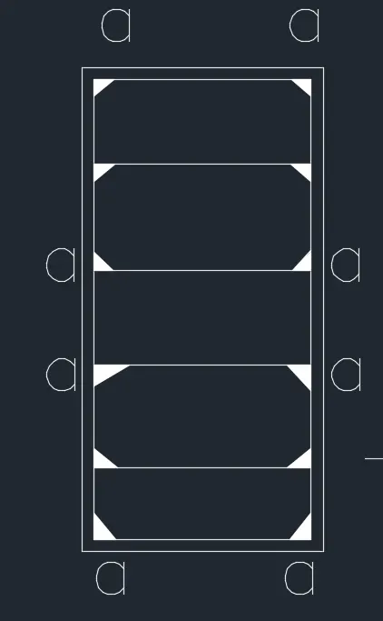
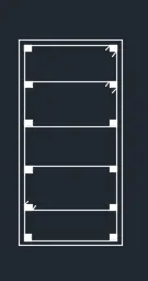
- Column C1a and Column C3 are provided with 12 bars of 16 mm dia bars.
- Column C2 is provided with 8 bars of 20 mm dia and 4 bars of 12 mm dia. The 20 mm dia bars are marked with 'a'.
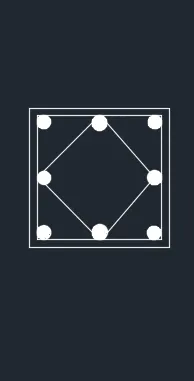
- Column C2a is provided with 8 bars of 16 mm dia.
- All columns are provided with 8 mm dia stirrups with 3" spacing c\c near the ends and 8" c\c in mid-length.
- The clear cover for all the columns is assumed to be 1.5" (approx 40 mm). As per IS 256, the minimum cover to the column should not be less than 40 mm
Commands used:
- Limits command
- Single Text command
- Line command
- Dimlinear command
- Trim command
- Mtext command
- Circle command
- object snap command
- DONUT command
- Divide command
- Offset command
- Units command
- Dimstyle command
- Extend command
- Mirror command
Procedure :
-
STEP:-1
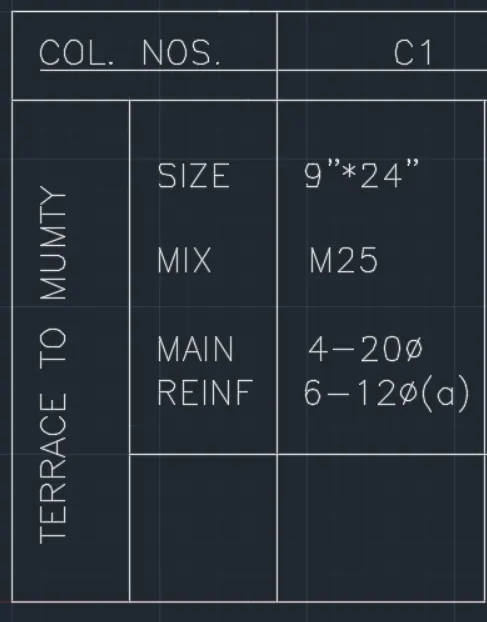
- Next we need to enter the details of columns with Single text and Mtext command.
- Then again we draw the column with given details as shown in below figure.
- First we draw the line with the length of 9" horizontally. • Next we draw the 24" line vertically, then again draw the line with the length of 9".
- Finally we join the first line and last line.
- Then after we do offset of 0.6", and do the offset to inside of rectangle we drawn previously.
- Next draw a circle beside of the previous figure, we take the circle diameter as 20mm And take another circle as diameter 12mm.
- Now use the divide command and give the 4 segments inside the rectangle.
- Now place the circle in the every segment.
- After putting the circles on one side, we use the mirror command.
- Mirror the one side fixed circles to other side. And put the 3 stirrups in the column where they are required to put in certain position.
- And Bend the corner of stirrups to the 45 degrees.
- And we denote the 12mm bars as "a", as shown in below figure.
- Here we need to enter the details of columns with Single text and Mtext command. Then again we draw the column with given details as shown in below figure.
- First we draw the line with the length of 9" horizontally.
- Next we draw the 24" line vertically, then again draw the line with the length of 9".
- Finally we join the first line and last line. • Then after we do offset of 0.6", and do the offset to inside of rectangle we drawn previously
- Next draw a circle beside of the previous figure, we take the circle diameter as 16mm
- Now use the divide command and give the 5 segments inside the rectangle.
- Now place the circle in the every segment. • After putting the circles on one side, we use the mirror command.
- Mirror the one side fixed circles to other side.
- And put the 3 stirrups in the column where they are required to put in certain position. And Bend the corner of stirrups to the 45 degrees, as shown in below figure
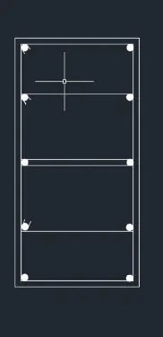
Step:-3
Column-2
- Here we need to enter the details of columns with Single text and Mtext command. . Then again we draw the column with given details as shown in below figure.
- First we draw the line with the length of 9" horizontally.
- Next we draw the 24" line vertically, then again draw the line with the length of 9". Finally we join the first line and last line.
- Then after we do offset of 0.6", and do the offset to inside of rectangle we drawn previously.
- Next draw a circle beside of the previous figure, we take the circle diameter as 20mm for 8 bars.
- And take another circle as diameter 12mm for 4 bars. Now use the divide command and give the 5 segments inside the rectangle. Now place the circle in the every segment.
- After putting the circles on one side, we use the mirror command.
- Mirror the one side fixed circles to other side.
- And put the 3 stirrups in the column where they are required to put in certain position.
- And Bend the corner of stirrups to the 45 degrees, as shown in below figure.
- And we denote the 20mm bars as "a", as shown in below figure.
Step:4
Column-2a
- Here we need to enter the details of columns with Single text and Mtext command.
- Then again we draw the column with given details as shown in below figure.
- First we draw the line with the length of 9" horizontally.
- Next we draw the 10" line vertically, then again draw the line with the length of 9".
- Finally we join the first line and last line.
- Then after we do offset of 0.6", and do the offset to inside of rectangle we drawn previously.
- Next draw a circle beside of the previous figure, we take the circle diameter as 16mm
- Now use the divide command and give the 2 segments inside the rectangle.
- Now place the circle in the every segment.
- After putting the circles on one side, we use the mirror command.
- Mirror the one side fixed circles to other side.
- And we have to put the 16mm bars in middle also.
- And Bend the corner of stirrups to the 45 degrees, as shown in below figure.
Step: 5
Column-3
- Now we need to enter the details of columns with Single text and Mtext command.
- Then again we draw the column with given details as shown in below figure.
- First we draw the line with the length of 9" horizontally.
- Next we draw the 24" line vertically, then again draw the line with the length of 9". . Finally we join the first line and last line.
- Then after we do offset of 0.6", and do the offset to inside of rectangle we drawn previously.
- Next draw a circle beside of the previous figure, we take the circle diameter as 16mm
- Now use the divide command and give the 5 segments inside the rectangle.
- Now place the circle in the every segment.
- After putting the circles on one side, we use the mirror command.
- Mirror the one side fixed circles to other side.
- And put the 3 stirrups in the column where they are required to put in certain position.
- And Bend the corner of stirrups to the 45 degrees, as shown in below figure.
Result :
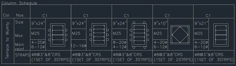
Figure : 02
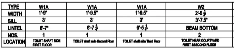
AIM: To Create a window schedule as shown in the figure:
Introduction :
The table contains the width, sill and lintel height, their numbers and respective location for different types of beams.
COMMANDS USED:
- Limits command
- Single Text command
- Line command
- Dimlinear command
- Trim command
- Object snap command
- Offset command
- Units command
- Dimstyle command
- Extend command
PROCEDURE:
STEP 1:
- In the command prompt type line to create tables
- In the command prompt type ST (text style ) > romans.shx (font name ) > 8" (height ) > center(justify )
- In the command prompt type text to text the given text in the drawing
RESULT:
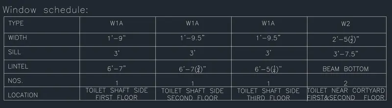
Figure : 03
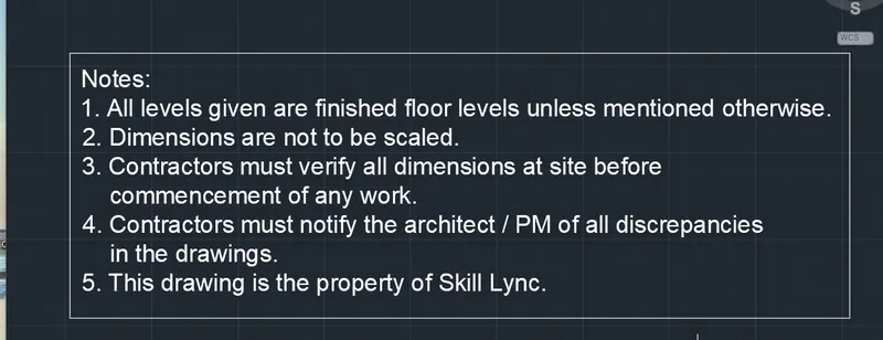
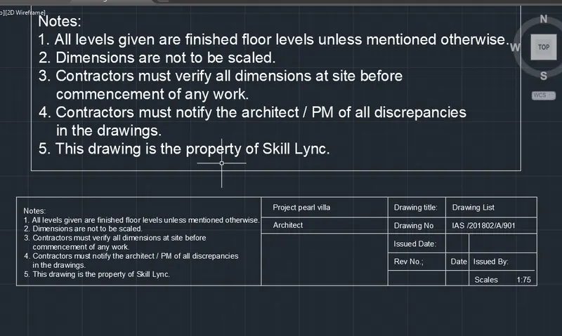
Create the drawing template as shown in the figure:< Use the Notes as in the figure>
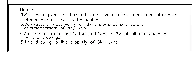

AIM: To create the drawing template for entering the details of the project.
INTRODUCTION:
Drawing template files are drawings that store styles, settings, layers, and layouts in a drawing including title blocks . When you create a new drawing based on a drawing template, the new drawing gets a copy of the styles in the template, but it is a one time copy.
COMMANDS USED:
- Limits command
- Single Text command
- Line command
- Dimlinear command
- Trim command
- Object snap command
- Offset command
- Units command
- Dimstyle command
- Extend command
PROCEDURE:
PROCEDURE:
Step 1:
- First off all we have to open the autocad and set the limits and units.
- Next we have to draw the table using the line command as shown in below table.
- We draw this table for the entering the details of the entire project before submitting to the client . After entering the details of the we submit the drawings to the client.
Step:2
- After drawing the table we have to select the Mtecxt command to enter the notes and project details. . And the text height will be kept to 8", and it is the standard text height for entering the details of the project in the table.
RESULT:
- The Drawing template was created successfully in the autocad in detail. And we drawn the drawing template and written their details in the tablular form as shown in figure.
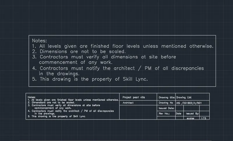
Figure : 04
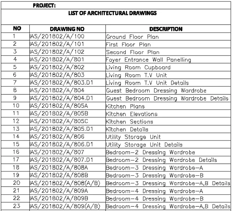
AIM: To Create the list of drawing schedule as shown in the figure:
INTRODUCTION:
- A schedule of drawings is an itemised list of drawings required for a building project.
- It can be included as part of an invitation to tender, or may be prepared as part of a design management plan. A schedule of drawings may include all the drawings required for a project, or on larger, more complex projects, it may be specifically prepared for a certain discipline, specialist or for a particular aspect of the works
Commands used:
- Limits command
- Table command
- Single text command
- Extend command
- Dimlinear command
PROCEDURE:
- In the command prompt type line to create tables .
- In the command prompt type ST (text style) > romans.shx (font name) > 8" (height) > left(justify) .
- In the command prompt type text to text the given text in the drawing .
RESULT:
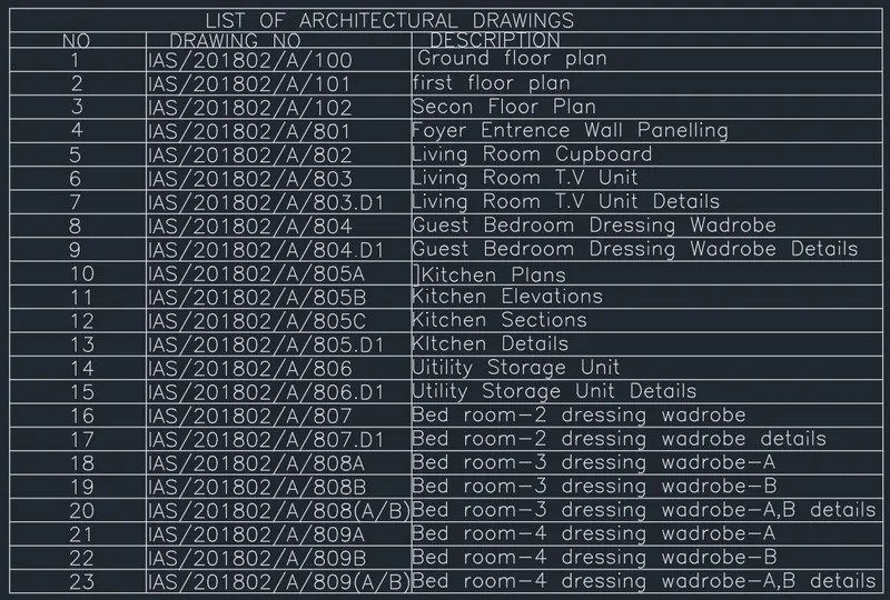
Figure : 05
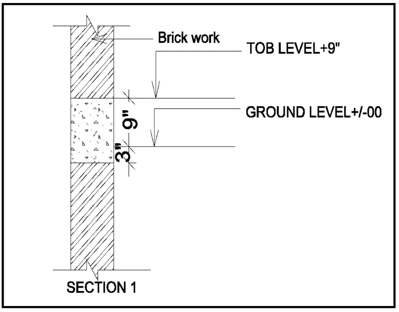
AIM: To Create the beam detail as shown in the figure:
COMMANDS USED:
- Limits command
- Single Text command
- Line command
- Dimlinear command
- Trim command
- Object snap command
- Offset command
- Units command
- Dimstyle command
- Extend command
- Hatch command
- Break command
PROCEDURE:
STEP 1:
- In the command prompt type UNITS > Engineering> Inches .
STEP 2:
- In the command prompt type Line (to create the column) .
- In the command prompt type Text to text the given drawings .
- In the command prompt type HATCH to hatch the given drawings .
RESULT: