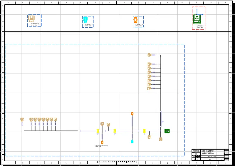
Project 1
AIM
Route the Wiring harness on Given Engine and Prepare flatten view drawing in CATIA V5. Application of all Packaging rules, Industry best practices studied in this course shall be demonstrated in design. Apply Protection coverings as required.
Theory :
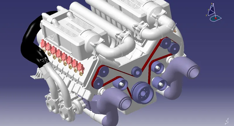
The given V-16 engine consist of following electrical components to which harness routing is required.
- 8+8 fuel injectors on the engine cylinders for both sides of the engine block (16 injectors), which are connected by a 4 pole connector with the wiring harness.
- 2 camshaft sensors on each engine block (4 camshaft sensors), which are connected by a 4 pole connector with the wiring harness.
- Engine coolant sensor at the centre of the engine between the two blocks, which is connected by a 2 pole connector, with the wiring harness.
- Engine oil temperature and pressure sensor fitted at the oil sump of the engine on both engine cylinder blocks, which are connected by a 2 pole connector with the wiring harness.
- 1 sensor to measure vehicle speed, which is connected by a 2 pole connector, with the wiring harness.
- 1 sensor to sense neutral positon of the transmission assembly, which is connected by a 2 pole connector, with the wiring harness.
- An interconnection connector to connect engine harness system to vehicle harness system.
Other equipments required to complete the wiring harness routing
- Guiding channels to protect the harness routing from high heat zones of the engine wherever necessary.
- P-clamps to provide positive clamping and ensure clearance management for the routing wherever necessary.
- Sheetmetal brackets such as L-clips to mount the interconnection connector.
- Mounting clips to mount the connectors whenever required.
- Corrugated protection tubes to protect the wiring harness.
Assumpions and packing rules :
- Wiring harness routing shall provide ease in manufacturing, accessibility, easy removal and easy maintenance of attached equipments and routing harness.
- Wiring harness should be routed in such a way that it is easy to assemble on a vehicle.
- Wiring harness should be kept away from sharp environments like sheet metal brackets, panel edges, corners etc.
- Avoid harness routing and clipping in blind zone of operator during harness during installation.
- Ensure that routing meets the clearance requirements with the different surrounding parts.
- Routing shall provide enough slack for each branch to avoid additional stress on wire and terminal crimping joints but ensure that extra slack does not cause wiring harness foul with surrounding parts and impact desired clearance requirements.
- Enough clamps should be provided to ensure the positive clearance with surrounding and safety of wiring harness.
- Use of plastic guided channels are recommended to meet the clearances in critical areas if it is difficult to achieve by use of clamps.
- Branch length should be minimum 50mm.
- Minimum distance between clip and nearest branching point should be 25mm.
- Minimum distance between two breakouts should be 50mm.
- Limit the no. of branches from single branch point to 4.
- Ensure that harness protection is provided according to surrounding temperature, manufacturabilty and expected reliability.
- The min. bend radius is to be 1.4.
- Consider min 5% slack in the wiring harness if needed.
ENGINE WIRING HARNESS ROUTING
Procedure :
Step 1. Create context assembly product file
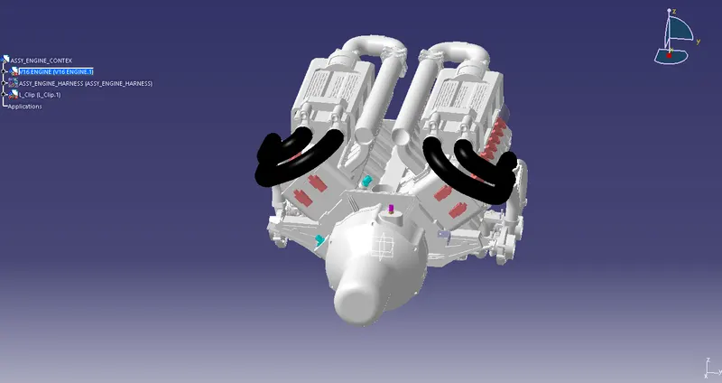
Create context assembly as shown in the image above. The context assembly will contain 3D CAD data for the engine and engine harness geometrical bundle assembly. Any sheet metal component such as L-clip required will be added into the context assembly.
Step 2. Define the connectors electrically
Before adding connectors into the geometrical bundle define all the required connectors electrically.
To define any connector electrically,
a. Create required geometrical parameters like bundle connection point, connector connection axis and cavity connection axis (if required) to the connector in the part design workbench as shown in the image below.
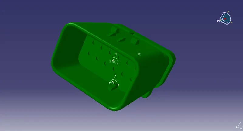
b. Now define connector with electrical properties such as connector connection point, bundle connection point and cavity connection point.
c.Go to electrical part design workbench and select connector command and input the no. of terminals as per the available connector.
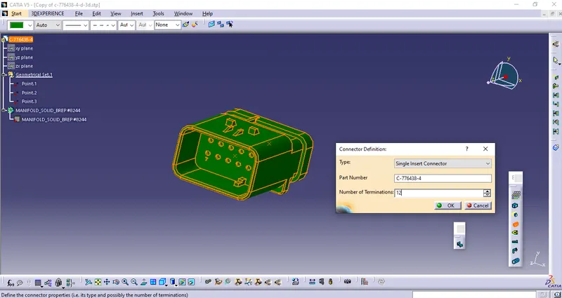
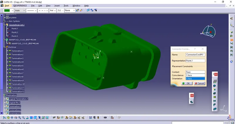
d. Defining connector connection point using connector connection point command and define the parameters as shown in the image below.
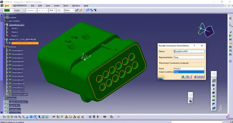
e. Define bundle connection point using bundle connection point command and define the parameters as below.
f. Define cavity connection point using cavity connection point command and defining the parameters as shown below.
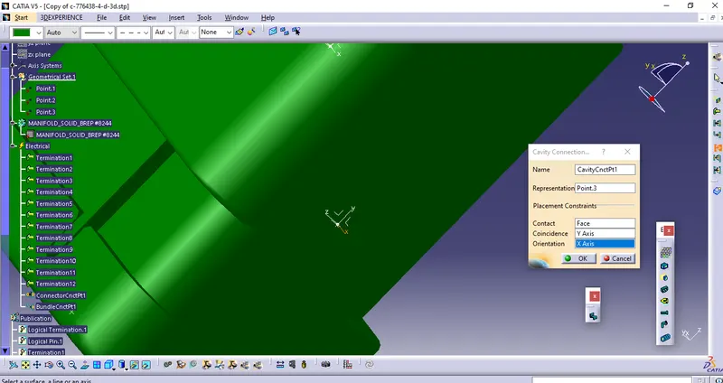
Hence the connector is defined electrically.
Use the same procedure to define all the connectors
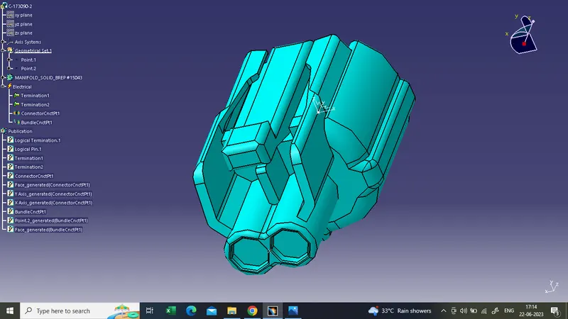
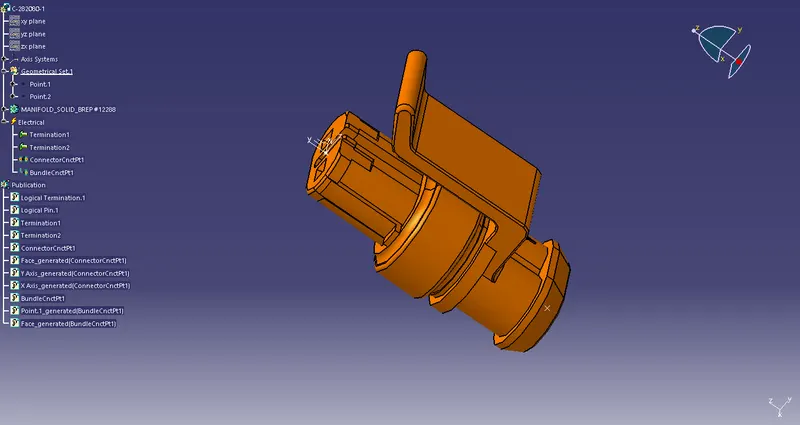
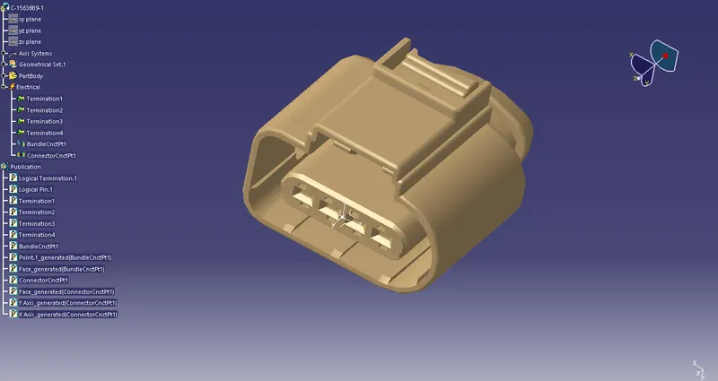
Create a catalouge using the Electrical part family and add the connetors
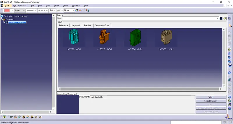
Step 3. Inserting connectors into geometrical bundle and positioning them.
a. The connectors are inserted into the geometrical bundle and positioned onto the fuel injectors, camshaft sensors, vehicle speed sensor, neutral position sensor and engine coolant sensor as shown in the images below.
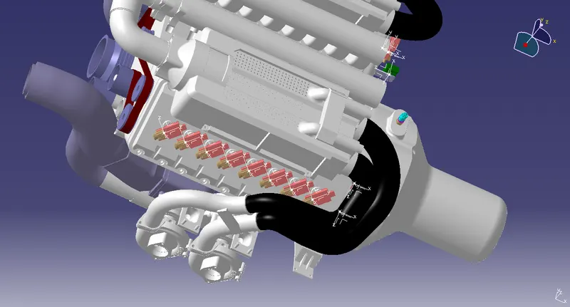
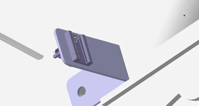
A sheet metal bracket (L-clip) is added inside the context assembly to mount the interconnection connector. The L-clip is added inside the context assembly and not into the geometrical bundle since it will not be bought along with the wiring harness. Existing bolt on the engine is used to mount the sheet metal bracket. The bracket should be provided with a suitable locking feature in clockwise direction. The ribs on the current engine design can be taken into advantage for the locking purpose so that it cant rotate freely. The design idea should be discussed with engine design team while using the existing bolts and screws so that there wont be any disturbance for the normal functioning of the engine as well.
To mount the interconnection connector onto the sheet metal bracket, first the mounting clip is mounted on the sheet metal bracket as shown below.
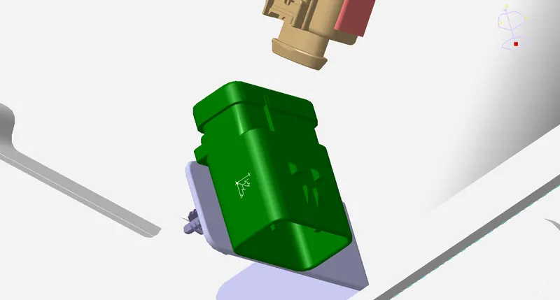
Then the interconnection connector is electrically connected with the mounting clip by using connect electrical devices command in the electrical assembly design workbench.
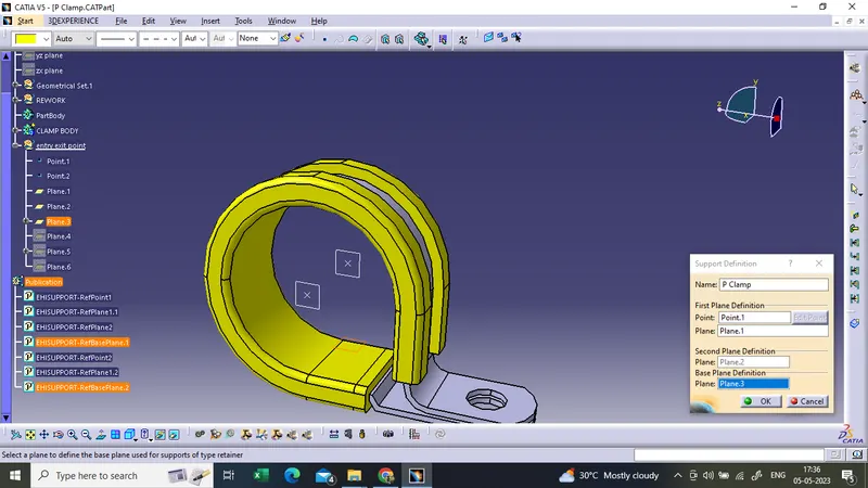
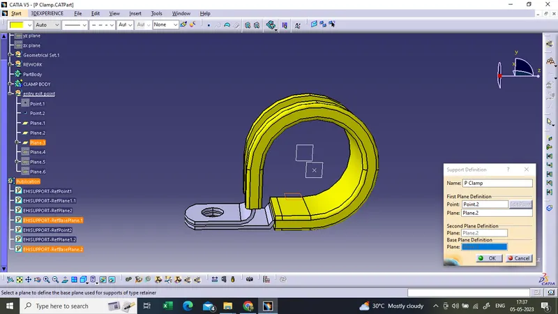
Adding P-clamps to provide positive clamping for the wiring harness.
P-clamps should be defined with electrical properties before inserting into the geometrical bundle assembly.
First define geometrical parameters such as entry point, entry plane, exit point, exit plane and base plane
process:
- Create two points one as entry and another as exit point.
- create planes at two points and another at base.
- Switch to Electric part desgn
- Click on support defination - select part - select entry point - select entry plane, exit and base plane.
- Again Click on support defination - select part - select exit point - select exit plane and base plane as secondary plane is automatically taken.

Adding plastic guiding channels
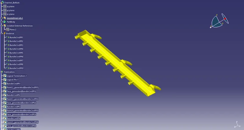
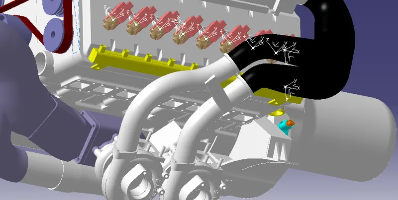
The given V-16 engine has 8 injectors both on the left and right side of the engine which are close to one another, hence using plastic guiding channels is the best option for easy and proper routing of the wiring harness and maintain clearance requirement of the wires from the high temperature parts of the engines.
Before adding guiding channels into the geometrical bundle assembly it is necessary to define electrical properties to it, which is done by following steps.
First create geometrical parameters such as bundle entry points, and external reference line in the part design workbench to route the wiring harness into the guiding channel
Go to electrical part design and define the part as equipment using equipment command and define bundle connection points using bundle connection point command towards the entry points of the guiding channel
Now insert the guiding channel into the geometrical bundle and position it accordingly as required, both on the left and right side of the engine
Routing the wiring harness to the connectors
Go to electrical harness assembly workbench and select geometrical bundle command and select the geometrical bundle in the model tree. Then select the multibranchable command to start the bundle routing and go to route definition.
i) The bundle routing starts from interconnection connector and then to the P-clamps and to the guiding channels.
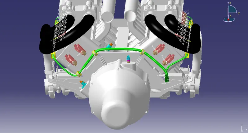
Adding branches wherever necessary to connect the various connectors to the main branch
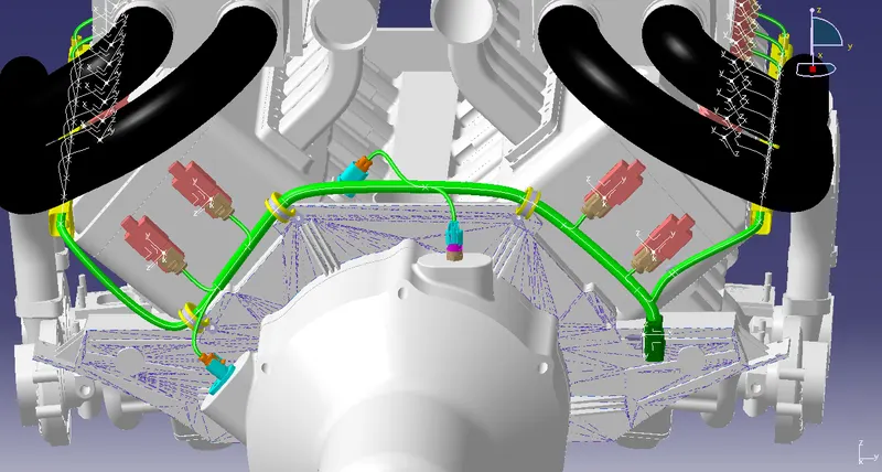
To route the wiring harness through the guiding channels select external curve and click on the line in the guiding channel.
Use branch defenetion to create branch in the guiding channel with some slack and the connect it with the connector
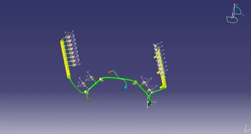
Check For bundel continuity
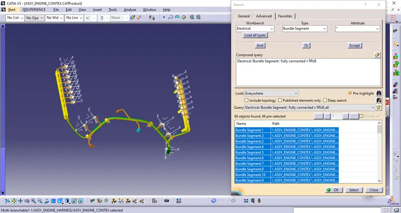
The Bundel is fully connected
Add protective covering such as Cot Tuebes which already added in the cataloge
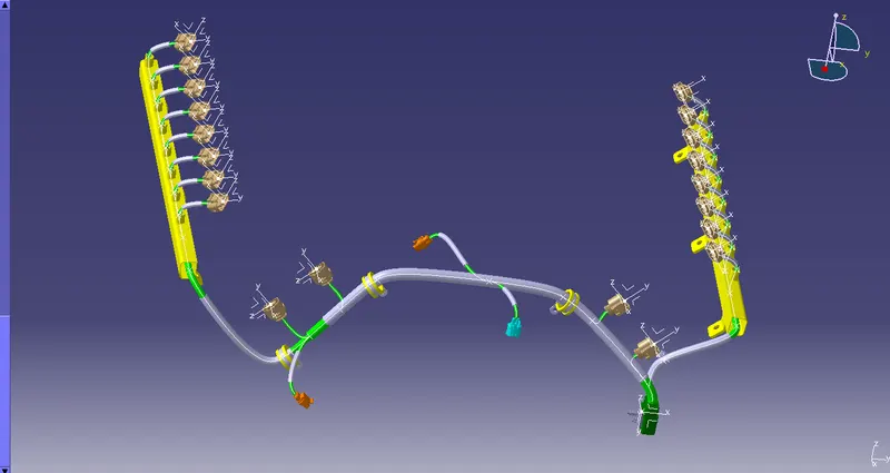
TO FLATTEN THE WIRING HARNESS AND DRAFT THE WIRING HARNESS ASSEMBLY.
HARNESS FLATTENING:
- WE GO TO THE HARNESS FLATTENING WORKBENCH AND DEFINE THE FLATTENING PARAMETERS.
- WE USE THE EXTRACT COMMAND TO BRING THE HARNESS ASSEMBLY TO THE FLATTENING WORKBENCH HERE.
- CHOOSING A SUITABLE PLANE WE FLATTEN THE HARNESS ASSEMBLY.
- BUNDLE SEGMENTS ARE ROTATED AT THE REQUIRED ANGLES. THE HARNESS ASSEMBLY IS THEN DRAFTED.
- FLATTENING PARAMETERS ARE DEFINED IN ORDER TO MAKE THE BUNDLE AND THE CORRUGATED TUBES VISIBLE IN THE 3D DRAWINGS.
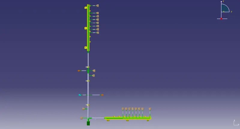
DRAFTING REPRESENTATION: