Project 1
AIM :
To Model & Design a Proposed Coil Centre, Chennai using STAAD. Pro for following input from Client.
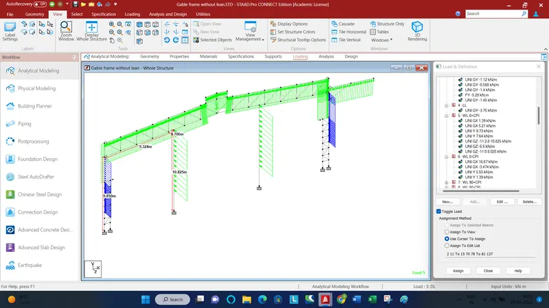
Design only a Main Frame with Lean (Grid 2) & Gable Frame without Lean (Grid 15)
Assume purlin load as 8.77 kg/m
Assume Gantry girder wt. = 158.24 kg/m
Assume Rail weight = 53 kg/m
PROCEDURE :
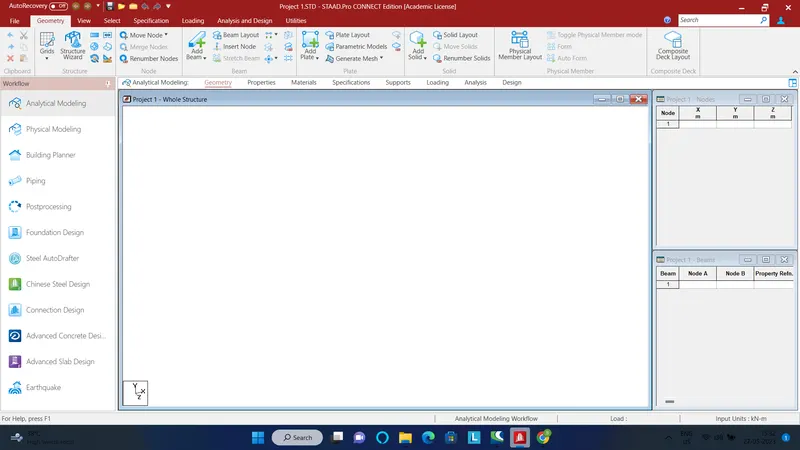
- Open a new project
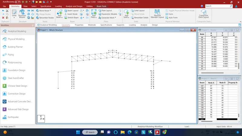
- Start creating nodes to form the main frame
- Add beams to connect the nodes
- Now add and assign properties to the members
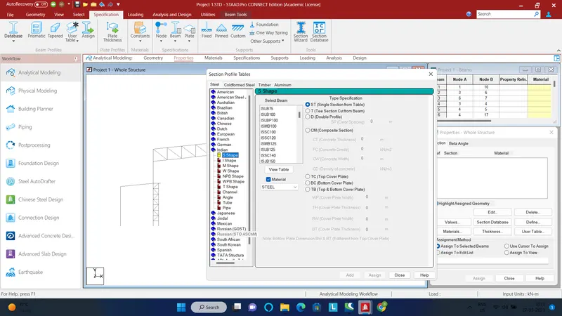
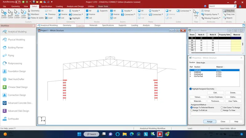
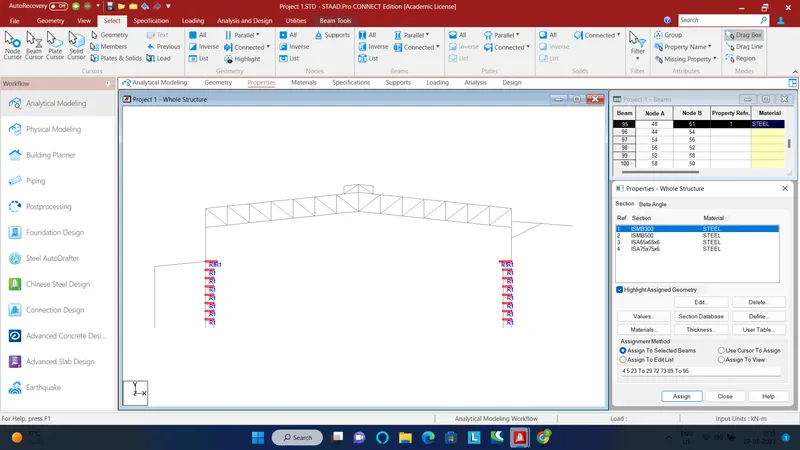
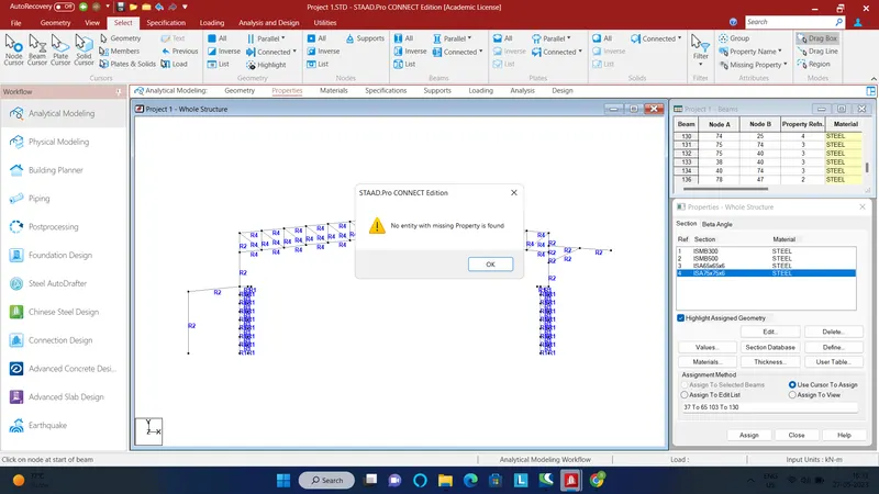
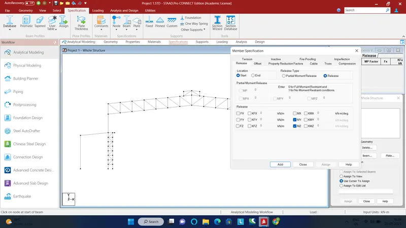
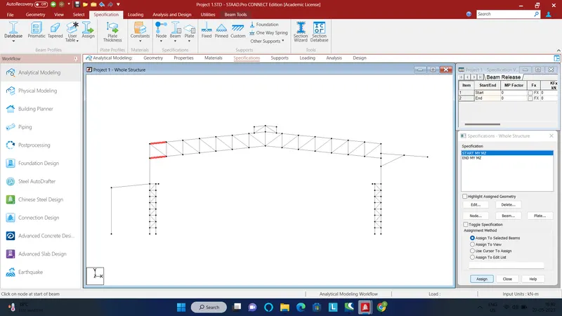
- Add appropriate specifications
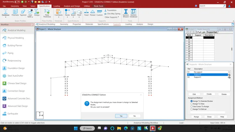
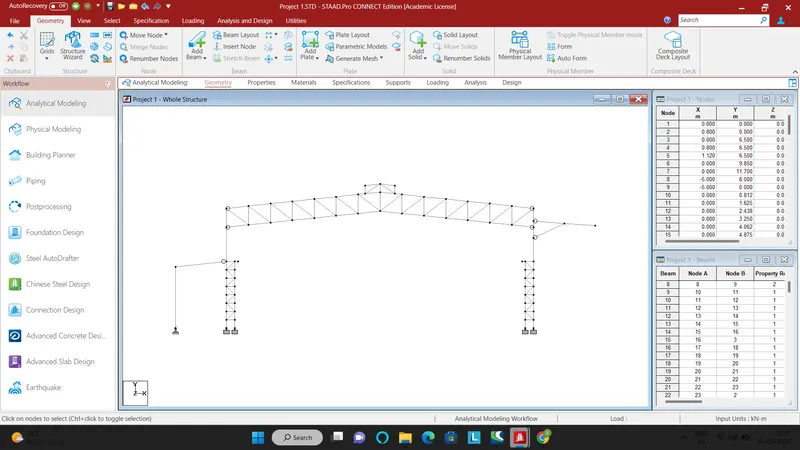
- Now add pinned and fixed supports and assign
Dead loads :
1) Sheet load
Dead load on truss = 0.14 kN/m2 x Bay spacing = 0.14 * 10 = 1.4 kN/m
DL + Collateral load on cantilever portion = (0.15 + 0.14) * Bay spacing = 0.29 * 10 = 2.9 kN/m
2) Purlin load
Purlin weight = 8.77 kg/m
Purlin load on truss = 8.77 * Bay spacing = 8.77 * 10 = 87.7 kg = 0.877 kN
Assume spacing of girts / purlins = 1.5m
Wall height = 5.2 m
Total no of purlins in Near Side Wall = (5.2 / 1.5 ) + 1 = 5 (on Wall)
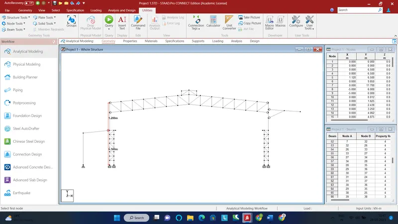
Wall height on crane supported column = 6.5 -2.8 (brick wall height) = 3.7m
Total no of purlins in Near Side Wall = (3.7 / 1.5 )+1 = 4 (on Wall- crane supported column)
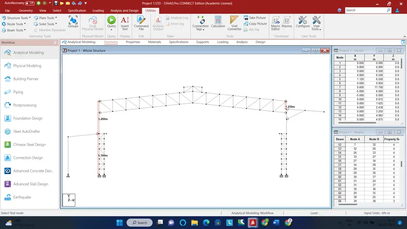
Wall height above cantilever = 1.25m
No of girts = (1.25/1.5)+1 = 2
Purlins/girts load on NSW = 5 * (8.77/5.20) = 8.43 kg/m2 = 0.084 kN/m2
Purlins/girts load on NSW(wall-crane supported) = 4 * (8.77/3.7) = 9.48 kg/m2 = 0.095 kN/m2
Purlins/girts load on FSW(wall - above cantilever) = 2 * (8.77/1.25) = 14.032 kg/m2 = 0.14 kN/m2
Total DL on NSW = [0.14 (Self weight ) + 0.084 (Purlins/girts load)] * Bay spacing = 0.224 * 10 = 2.24 kN/m
Total DL on NSW(wall-crane supported) = [0.14 (Self weight ) + 0.095 (Purlins/girts load)] * Bay spacing= 0.235 * 5 = 1.175 kN/m
Total DL on FSW(wall-above cantilever) = [0.14 (Self weight ) + 0.14 (Purlins/girts load)] * Bay spacing= 0.28 * 10 = 2.8 kN/m
3) Gantry load:
Assume Gantry girder wt. = 158.24 kg/m
Assume Rail weight = 53 kg/m
The Frame is spaced at 10 m bay spacing whereas the Gantry girder is spanning 5 m
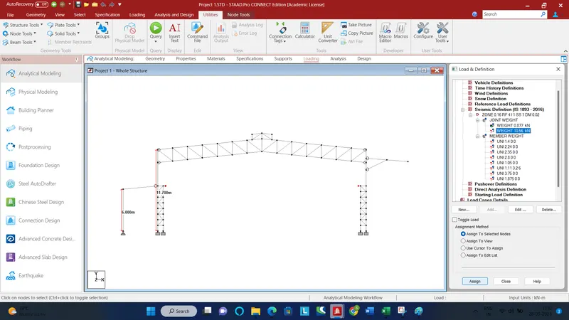
Weight on Bracket = 211.24 * 5 =1056.2 kg = 10.56 kN
4) Loads on Lean:
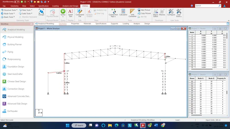
No of purlins on roof of lean = (5.025/1.5) + 1 = 4
Purlin load on lean = 4 * (8.77/5.025) = 6.98 kg/m2 = 0.07 kN/m2
DL on lean = [0.14 (Self weight ) + 0.07 (Purlins/girts load)] * Column spacing = 0.21 * 5 = 1.05 kN/m
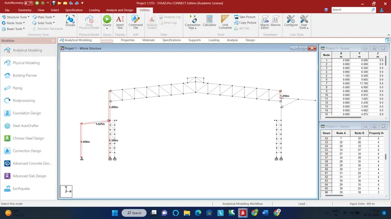
Height of the wall(above brick wall)= 6 - 2.8 = 3.2 m
No of girts = (3.2 / 1.5) + 1 = 3
DL of girts = 3 * (8.77 / 3.2) = 8.22 kg/m2= 0.082 kN/m2
DL on wall of lean= [0.14 (Self weight ) + 0.082 (Purlins/girts load)] * Column spacing = 0.222 * 5 = 1.11 kN/m
Live loads:
Live load on truss = 0.75 kN/m2
LL = 0.75 * 10(Bay spacing) = 7.5 kN/m
LL on lean = 0.75 * 5(Column spacing) = 3.75 kN/m
Wind loads:
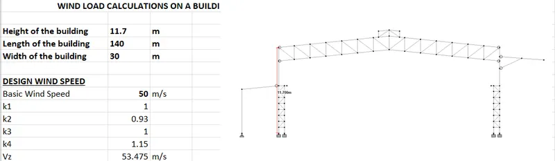
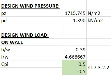


On roofs:
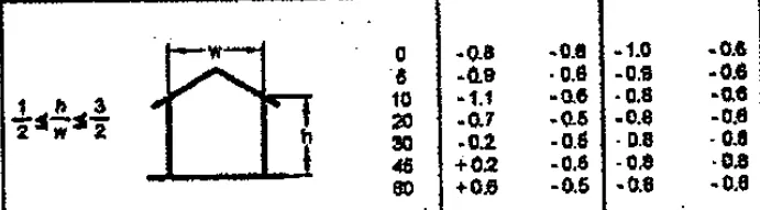
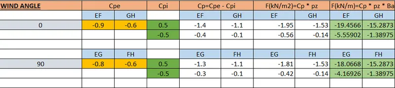
Seismic Load:
Zone factor = 0.16 (Since structure is in Zone 3)
Response reduction = 4
Importance factor = 1
Soil type = Hard
Crane Load:
Crane capacity = 30 MT
Crane capacity including hoist = 35 MT
Vertical impact = 25%
Load = 1.25 (300 + 350/2) = 593.75 kN
Lateral impact = 20%
Load = 0.2 * (350/2) = 35 kN
Load application:
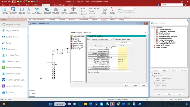
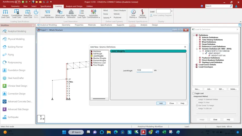
Similarly add DL member weights
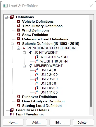
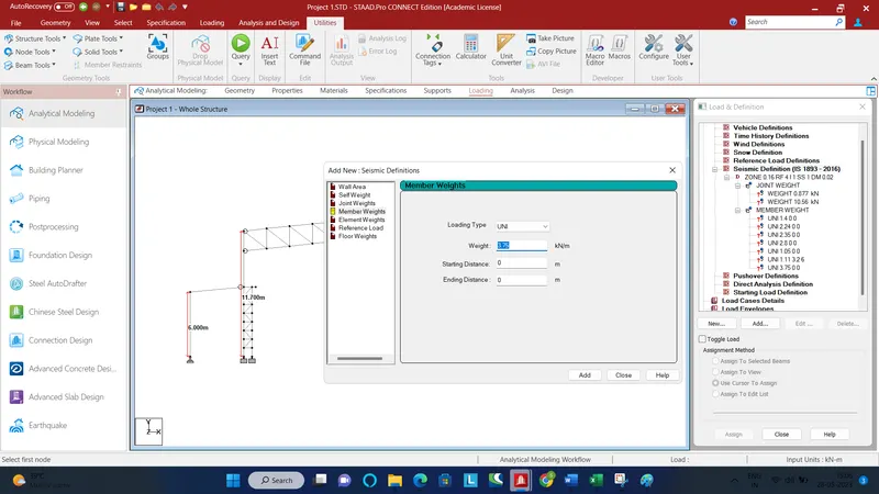
Add half of the live load in Sesimic definition member weights
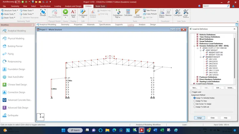
Joint weight on truss from purlins
Joint weight on brackets
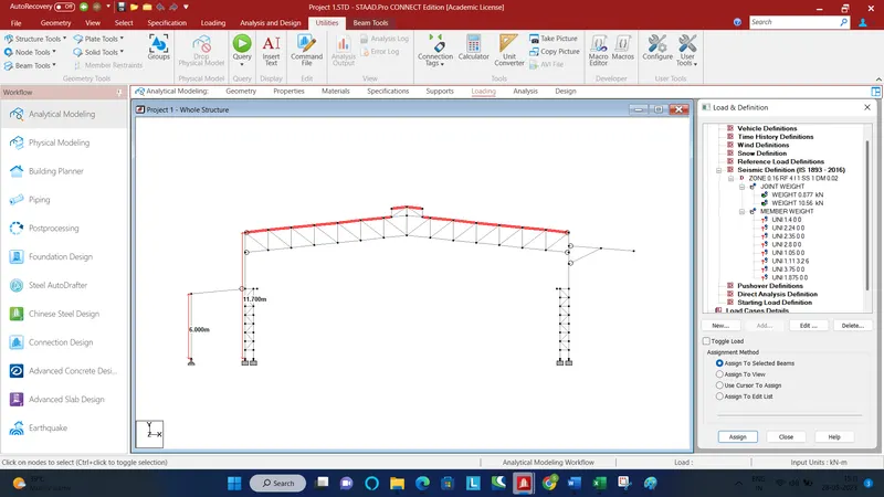
Member weight on truss due to sheeting
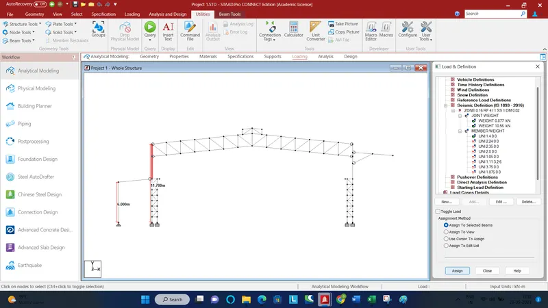
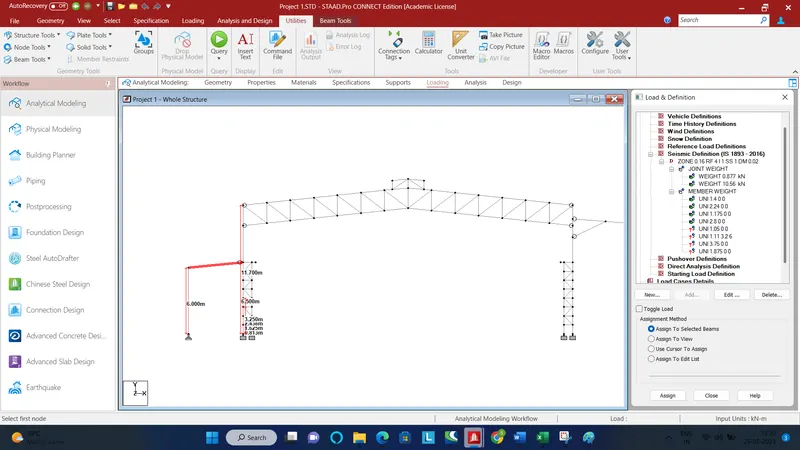
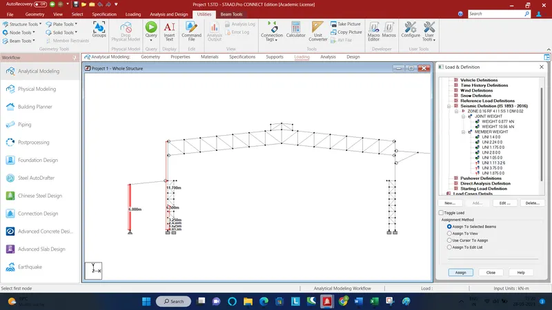
Member weight on columns
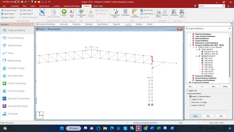
Member weight on lean
LL on truss
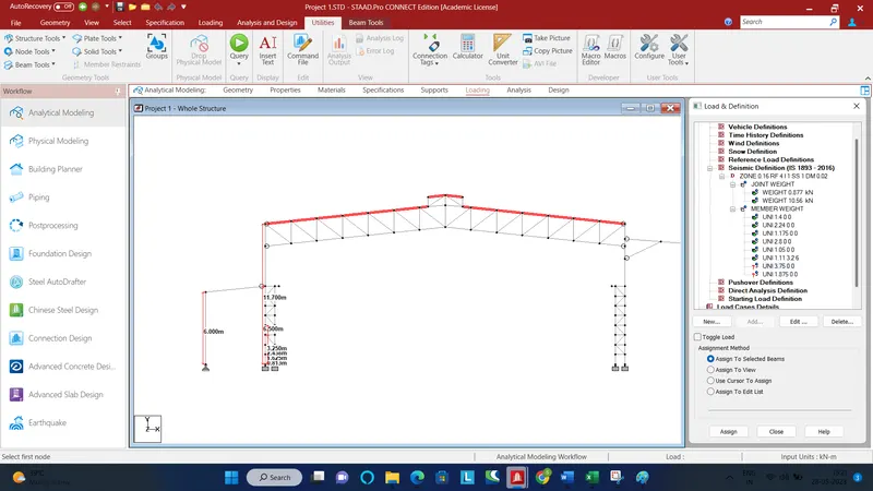
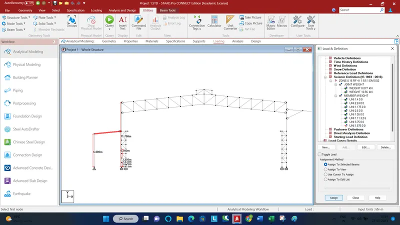
Now add the EQ load cases in X and -X directions under load case details
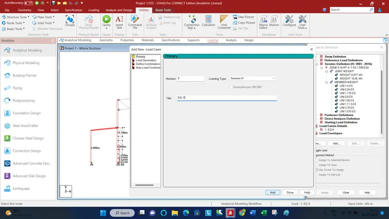
Now add DL cases
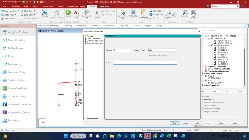
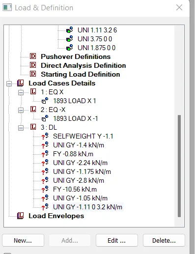
Add other DLs
Now add live loads
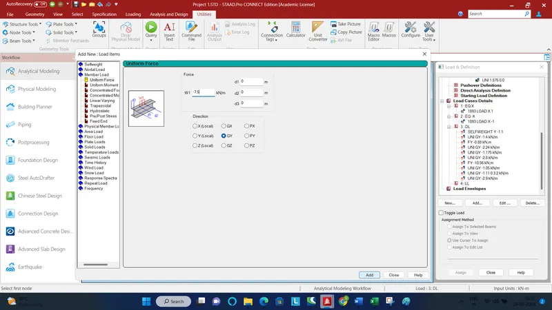
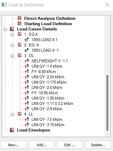
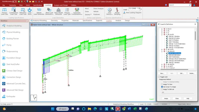
Add wind loads
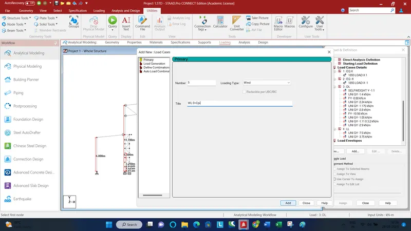
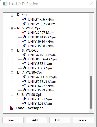
Crane load
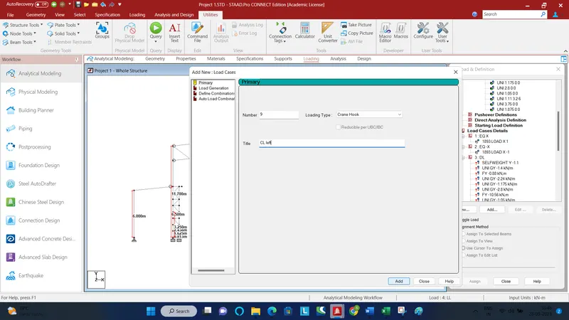
Add nodal load against Fx and Fy. Fx lateral impact load and Fy vertical impact load
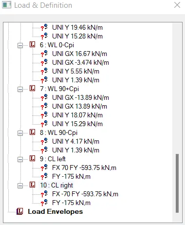
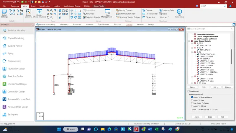
Now start applying the load on the relevant members
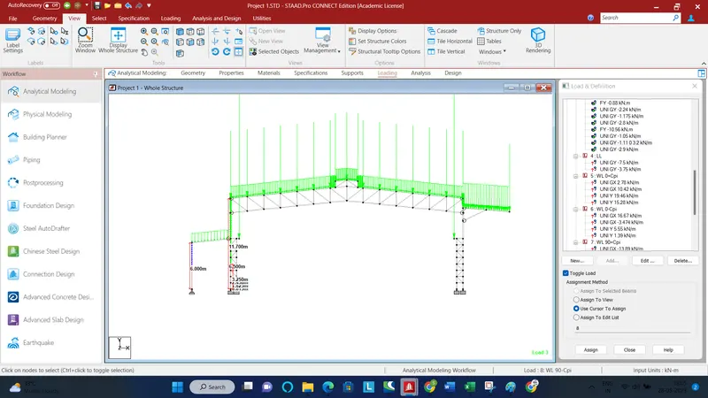
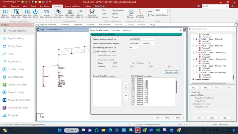
Now create automatic load combinations
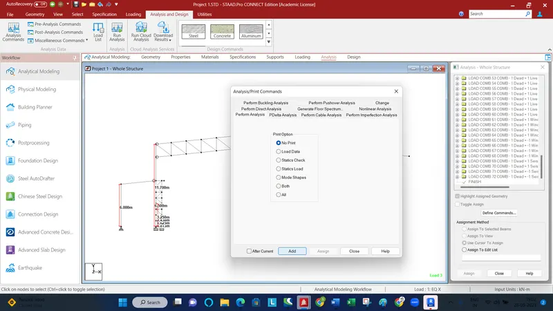
Analysis and Design
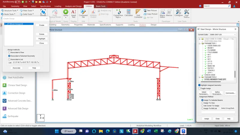
Assign parameters for design
GABLE FRAME WITHOUT LEAN
Save the above file as gable frame
Add the wind columns
The gable frames carry only half the loads as the main frame. So divide all the loads by 2.
First modify the seismic definitions
In the load cases add EQ +/- Z also
For the wind load add loads for C side also. Add half the load to the end post.