Project 1
REPORT :
AIM :
To Route the wiring harness on the given engine and prepare flatten view drawing in the catia V5,Application of all packaging rules.
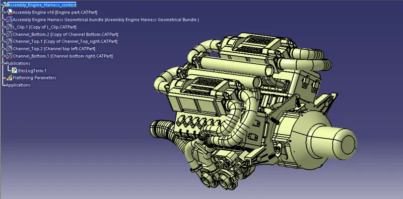
This is the Engine block that the wiring harness should be routed by considering the design considerations.
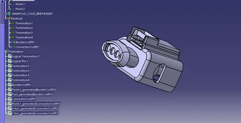
This is the C-1563689 connector that should be defined electrically,it has four terminals ,This connector acts has the nozzle to the engine there are total of 16 nozzles to the engine 8 on each side.
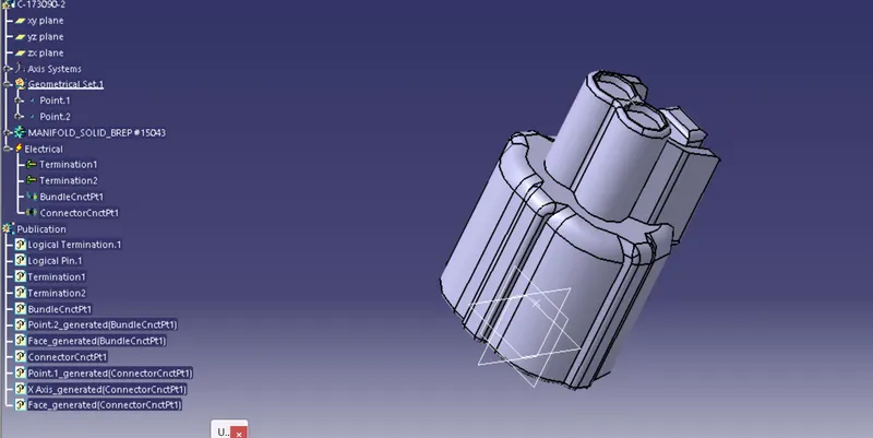
This is the C-173090 connector that should be defined electrically,it has 2 terminals in which it is used has the temperature sensor to detect the temperature.
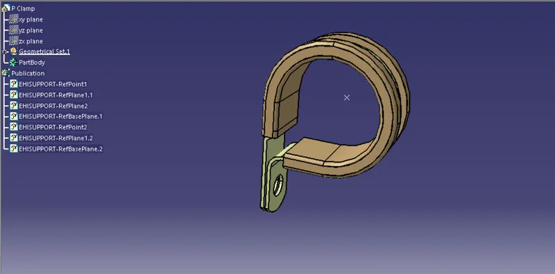
This is the P clamp that should be used defined has support and the support planes has be be defined
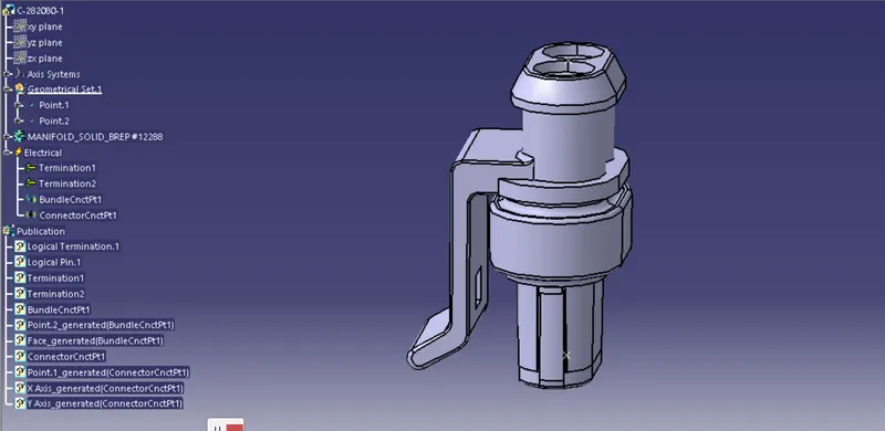
This is the C- 282080 connector that should be defined electrically,it has 2 terminals in which it is used has cam sensing
Step 1 :
In this step define all the connectors electrically including all the 2 and 4 terminals individually,Now take a new product file and name it has assembly engine harness context and add the engine block file has assembly engine v16.
Step 2:
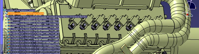
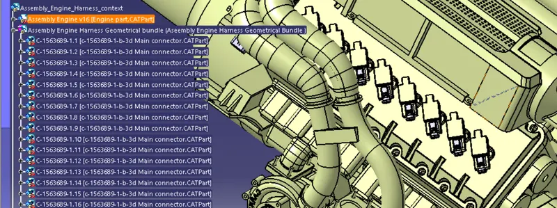
In this step add the new file has assembly engine harness geometric bundle,Now under the assembly engine harness geometric bundle add the first connector has C-1563689 has copy and past it 16 times till all the nozzles of the engine is connected with connector bu using the command snap fit in the assembly design workbench and insert the respective temperature sensor connector and the cam sensing connector.
Step 3:
In this step decide the wiring harness path in such a way the harness should be simple,enough slag should be provided,No flouling with other components and no extra wire length should be provided if extra wire length is provided then the wire haules with the components downwards and effects the service of the wires. by considering all the above conditions the wiring harness design should be made.
Step 4 :
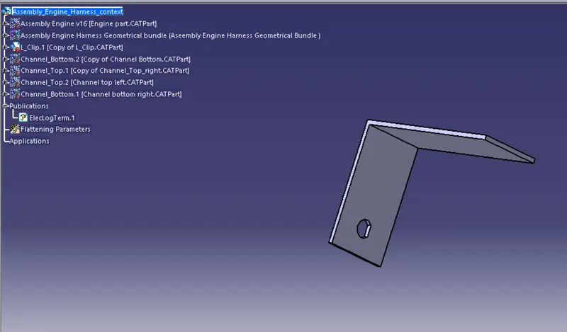
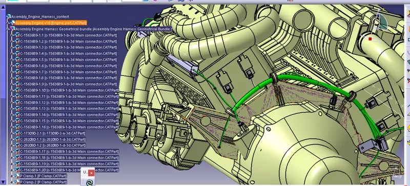
Now insert the L clamp,P clamp and the furr tree clips where ever necessary has shown in the figure below
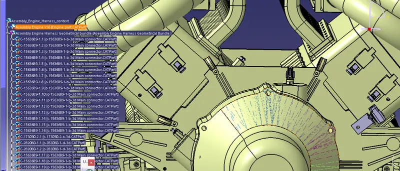
Step 5 :
Now activate the geometric bundle in the wiring harness design and route the respective p clamp and the L clamp and the furr tree clips by giving the necessary input of the bend radius,slag and the diameter of the bundle
Step 6 :
In this stage Now insert the channel bottom at one side of the nozzle ensure that it fits perfectly in the given area in the same way now take the individual part of the channel bottom in the seperate part file and convert the channel bottom by using the symmetry option so that this channel bottom fits on the other side of the nozzles.
Step 7 :
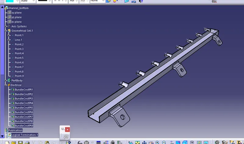
Now define the channel bottom has the mounting equipment and define the bundle connectings points at all the open portions. for both the channel bottoms.
Step 8 :
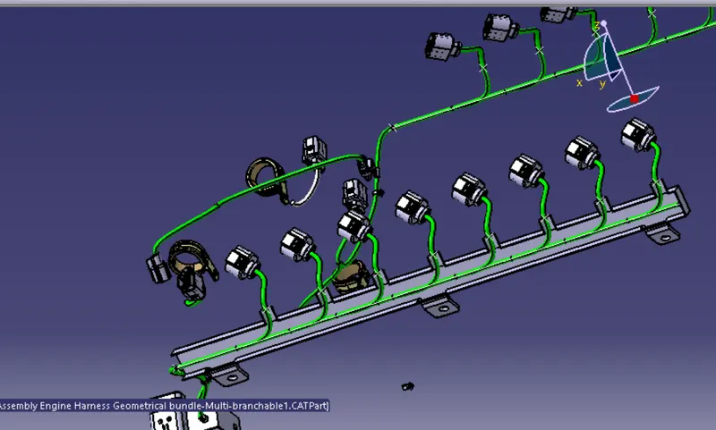
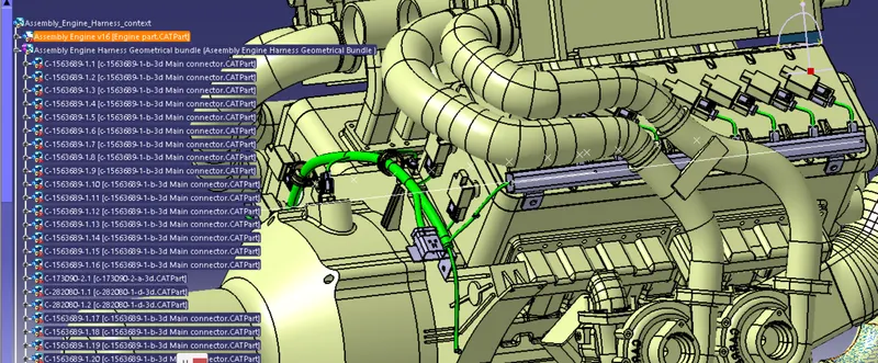
In the channel bottow draw a line for routing the harness at the centre of the channel,By defining the bundle segment has external curve route inside the channel,After then connect the channel and bundle connections points has given in the below figure.
Step 9:
Connect the connector and the bundle connection points on both the sides and close the channel bottom with the channel top on both the sides.
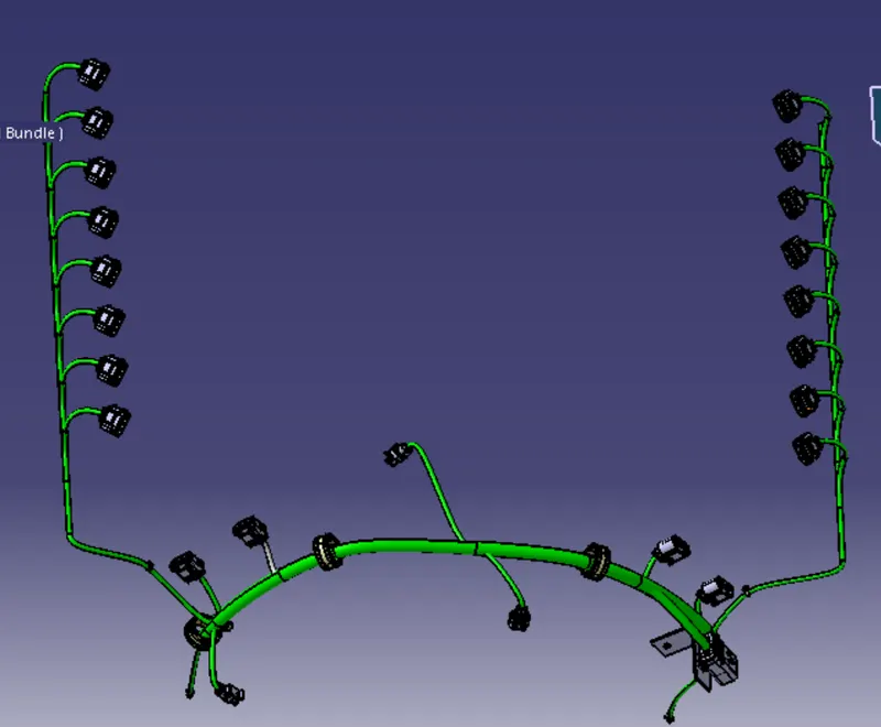
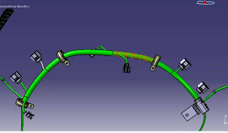
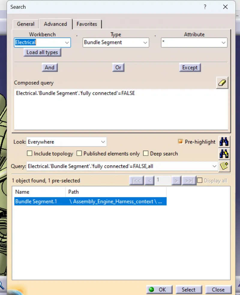
The temperature connectors and the cam connectors are connected at the respective places by taking add branch point near to the connectors,finally do a test in the edit section < search <advanced and give the necessary inputs and select has flase the output is displayed.
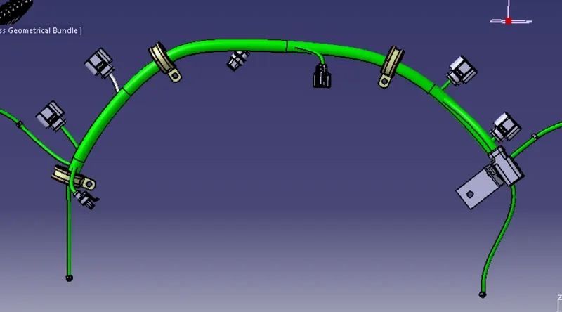
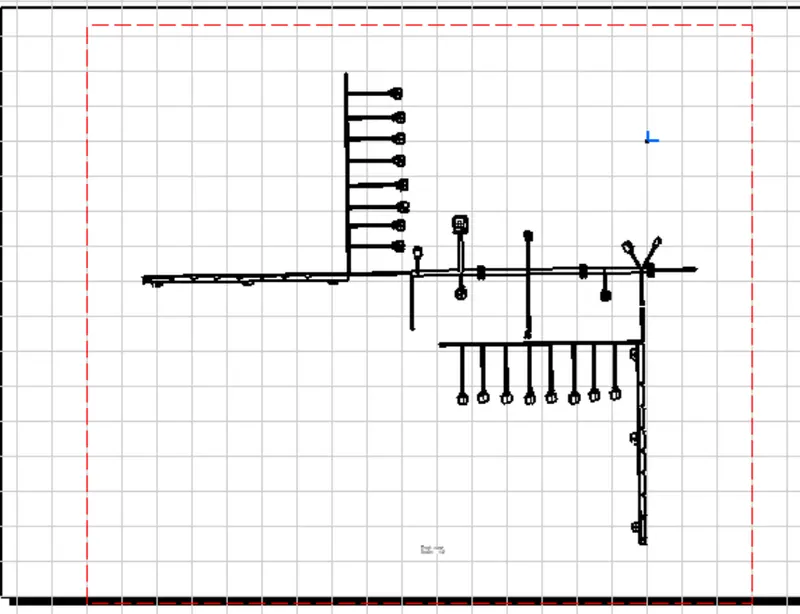
Flatten the wiring harness geometrical bundle and create a drawing and also convert the drawing into pdf
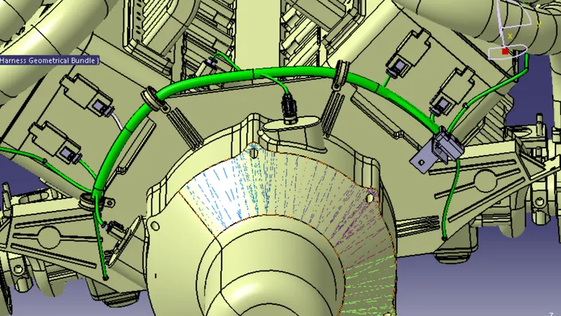
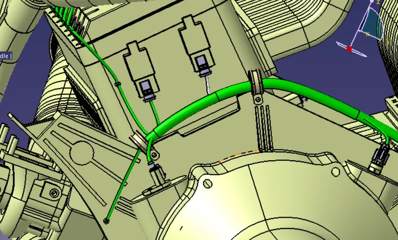
The Final Aseembly of the Engine harness v16
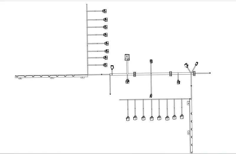
CONCLUSION :
Therefore all the given conditions are satisfied has per the given guide lines and flattening of the geometrical bundle harness is also done