Project 1
ANS:-
AIM:-To analyse and Design a steel Building to 10T CRANE as per IS standard code in TEKLA structural Designer and to design a structure according to the attachments provided.
PROCEDURE:-
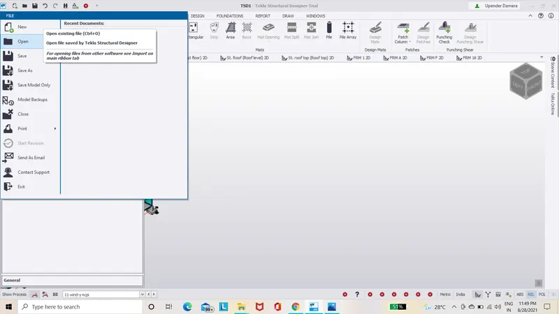
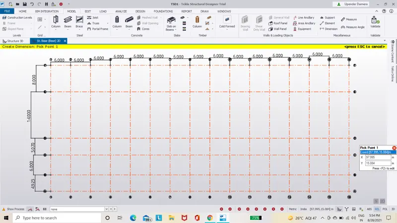
- First we have to open the TEKLA software and open new file and draw the grid lines using the grid lines option.
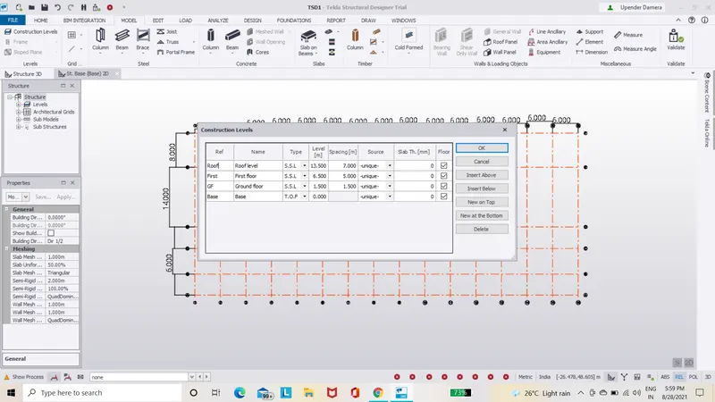
- Next define the different levels such as Base level,Ground level,First floor,Roof level and Roof top level appropriately according to the plan.
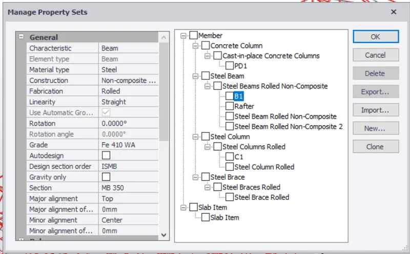
- Next we have to select manage property sets and adding members like concrete clolumn,steel column and steel bems.
- Adding the elements with appropriate properties.
- Placing the concrete column from base level to groud level.
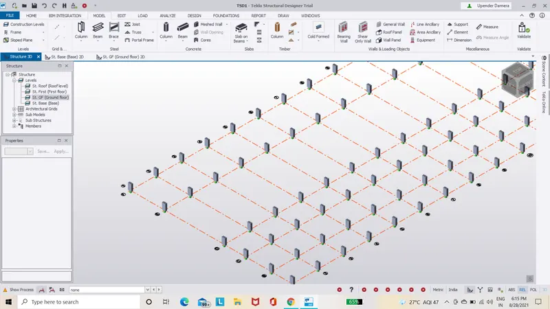
- Next we have place the steel column from ground to first floor level as shown below.
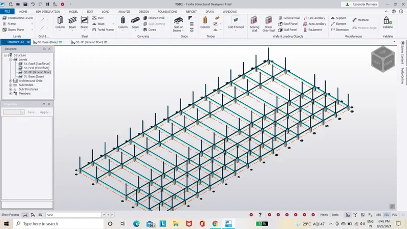
- Placing the primary steel beam on ground and first floor.
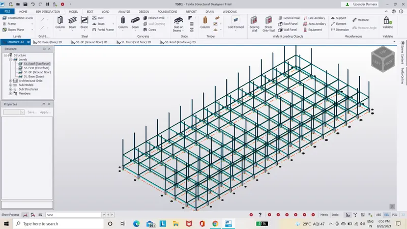
- Next we have to add the crane at the first floor as shown below.
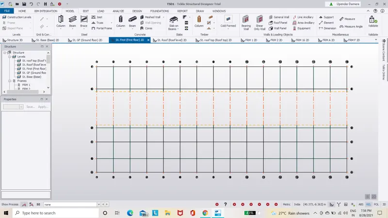
- Next we have to make the crane beam as cantilever on fixity end 2.
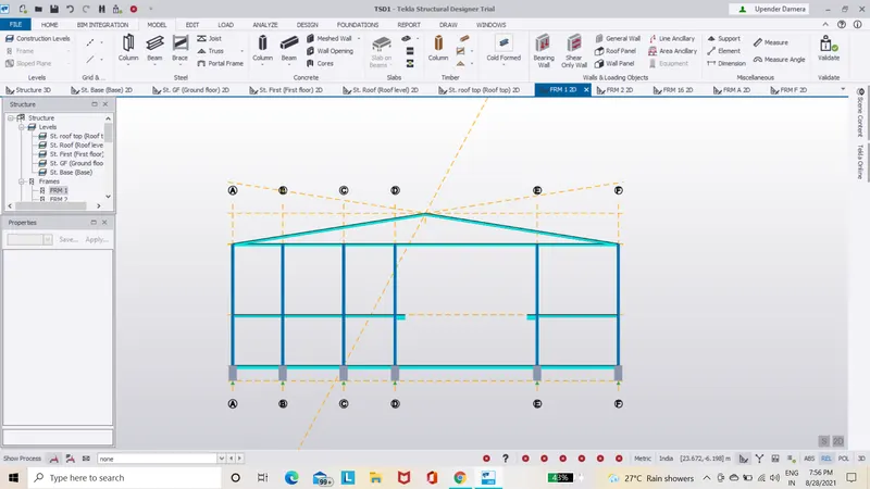
- Next define the rafter beams and assigning it to the top floor and setting the rafter beams to be fully fixed at both ends.
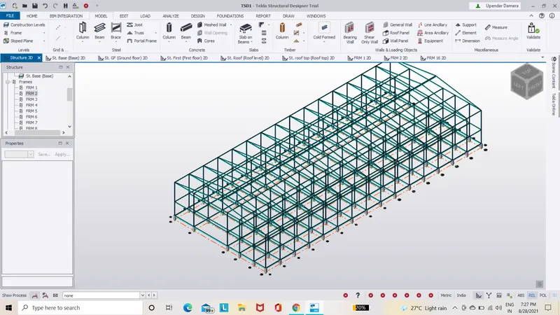
- Next we have to crate different frames by using the frame option in the ribbon as shown below.
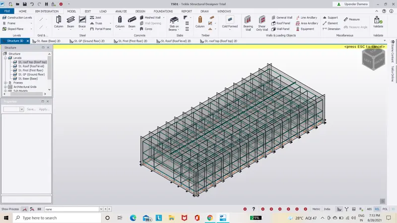
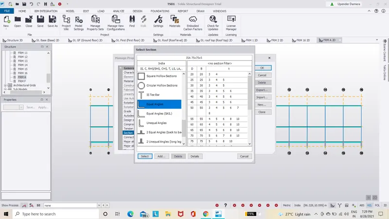
- Then we have to define the bracing using manage properties set and assigning it to the appropriate locations selecting ISA equal angles for the bracing.
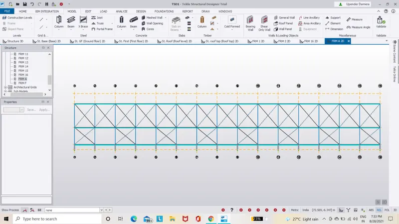
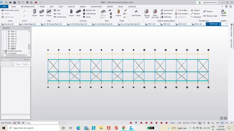
- Next we have to assign the roof panel to the roofs by using the roof panel option and assign it to the roof topin model command.
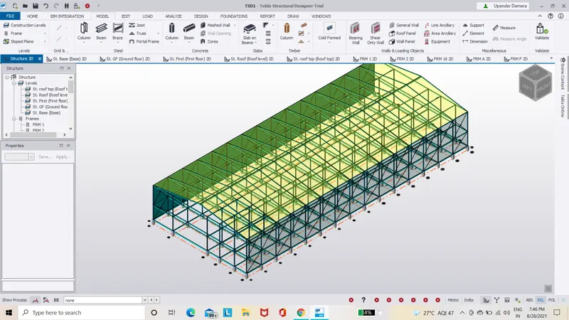
- Also we have to assign the wall panels to the frames Frame1,Frame16,Frame A and Frame D.as shown below.
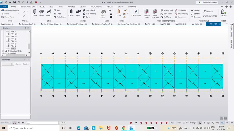
- Next we have to define the slab propertis as slab on beams and making the thickness as 200mm and using M30 concrete and giving it two way slab rotation angle as 90 degree and assigning the same to the ground floor and first floor.
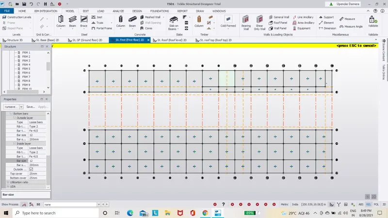
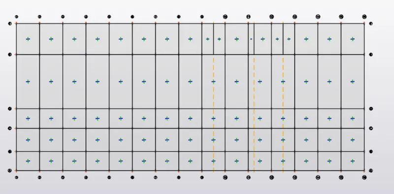
- Next we have to calculate the loads same as shown below.
LOAD CALCULATIONS:-
- Dead load of 1.2KN/m2.
- Finishes =50mm x 24 KN/m3=1.2kn/m2.
- Brickwall load=0.15 x 20 x 5=15 kn/m( Ground floor tp first floor).
- Brickwall load=.15 x 20.7 = 21kn/m2( first floor to roof floor).
- Brickwall load=0.15 x 20 x 4.8 =14.4 Kn/m2( Roof to top floor).
- Roof load =1.5kn/m.
- Ceiling load=0.3kn/m.
- Next we have define the following load cases.
- Also define the load combinations as shown below.
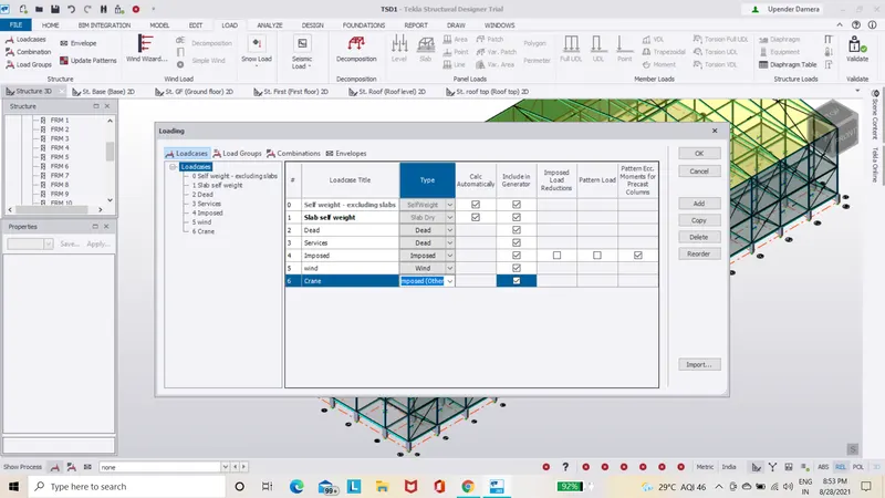
- Next we have to apply the Dead load to tthe all floor levael as shown below.
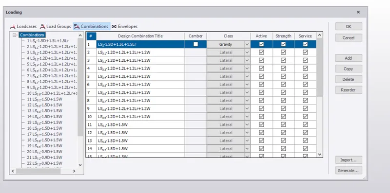
- Go to loads select the load as dead load and selecting the area load and entering the value of 1.2kn/m applying the load rom ground floor to the roof floor slabs.
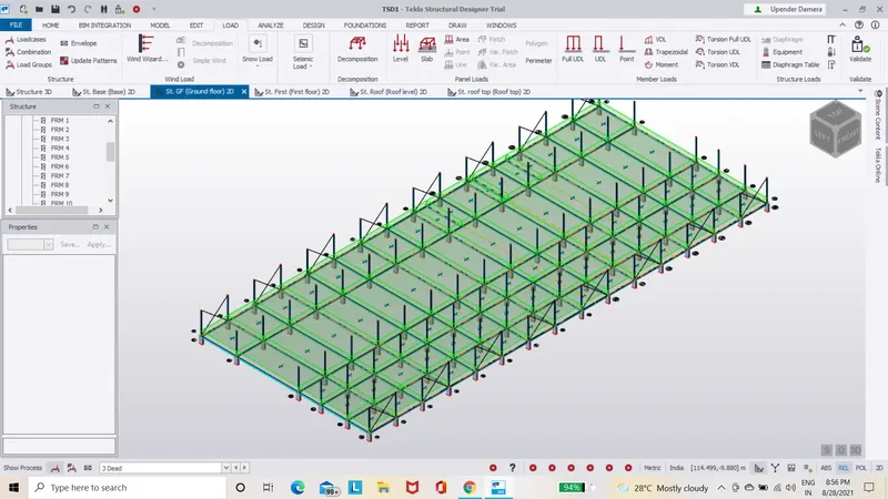
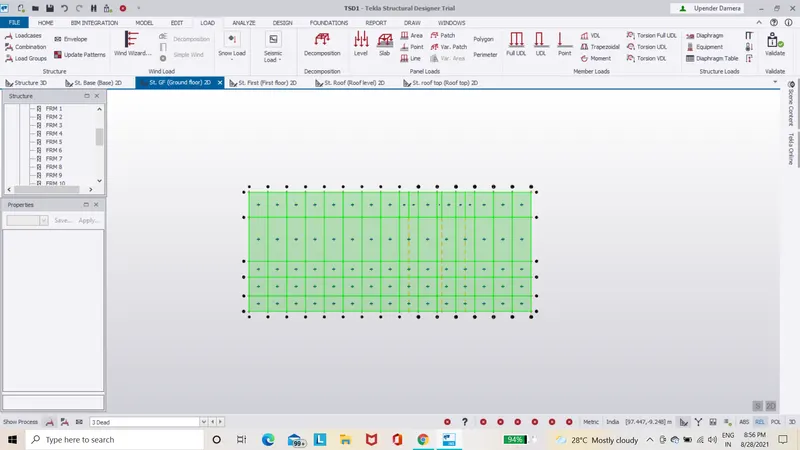
- Next we have to apply the brickwall loads as shown below.
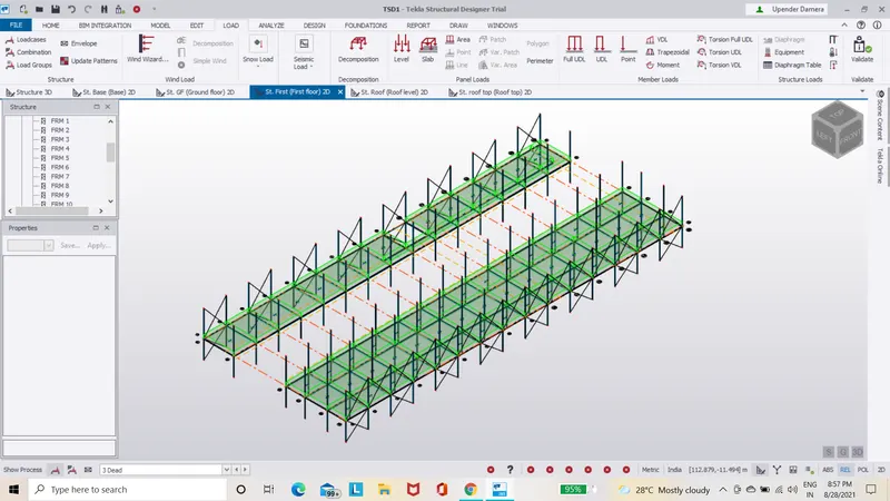
- Selecting the load as brickwall load and apply the brickwall load of 15 kn/m to the Ground floor to first floor.
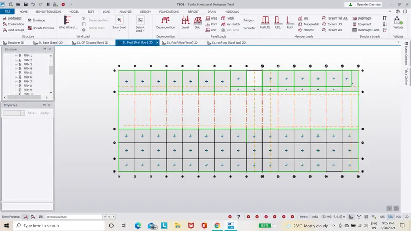
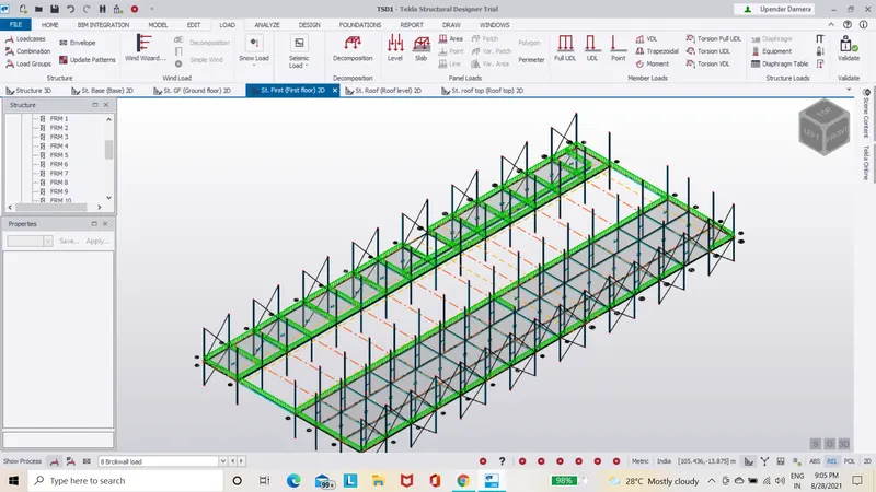
- Next we have apply the brickwall load of 21kn/m2 to the first to roof floor as shown below.
- Next apply brickwall load of 14.1kn/m2 to the roof to top top roof level as shown below.
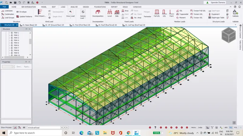
- Next we have apply the live to the all floor levels as shown below.
- As per IS 875 live loads are
- Staircase=5KN/m2.
- Workshop=5kn/m2.
- office=3kn/m2.
- storeroom=5kn/m2.
- Toilet =2kn/m2.
- Apply above live loads to the all floor levels as shown below.
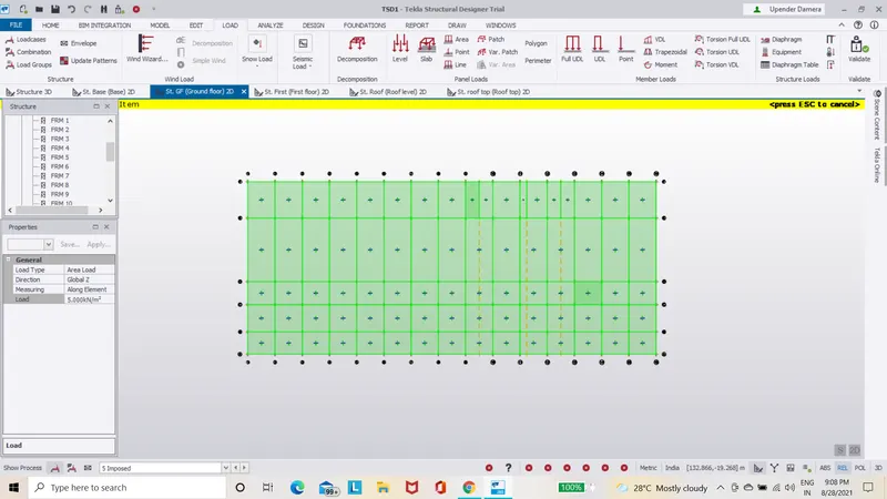
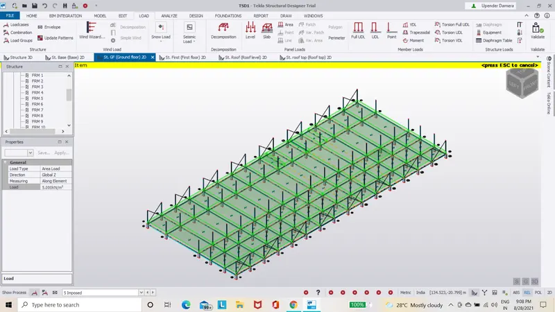
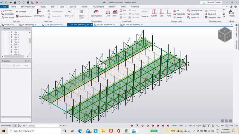
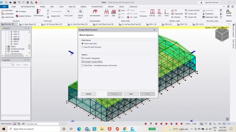
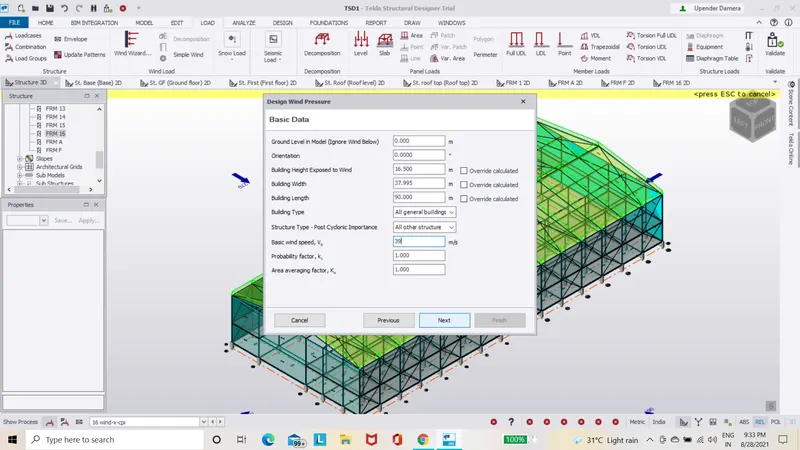
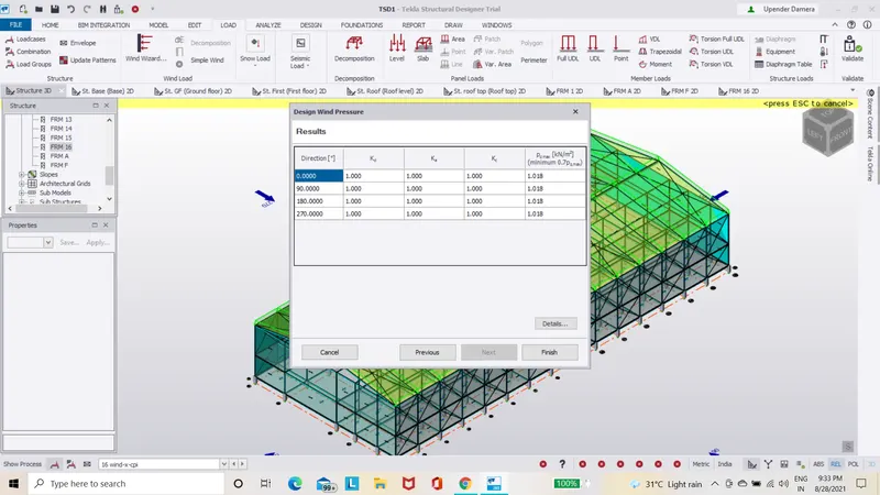
- Next we have to apply wind loads to the wall panels and roof panels by selecting the different frames.
Wind load calculations:-
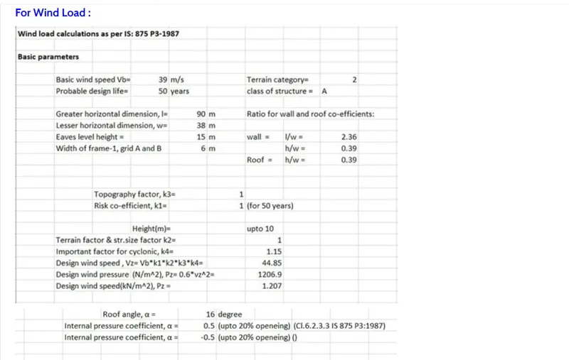
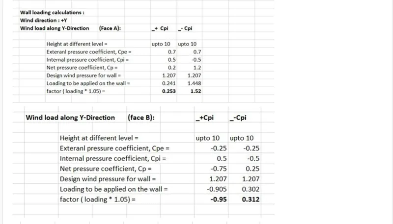
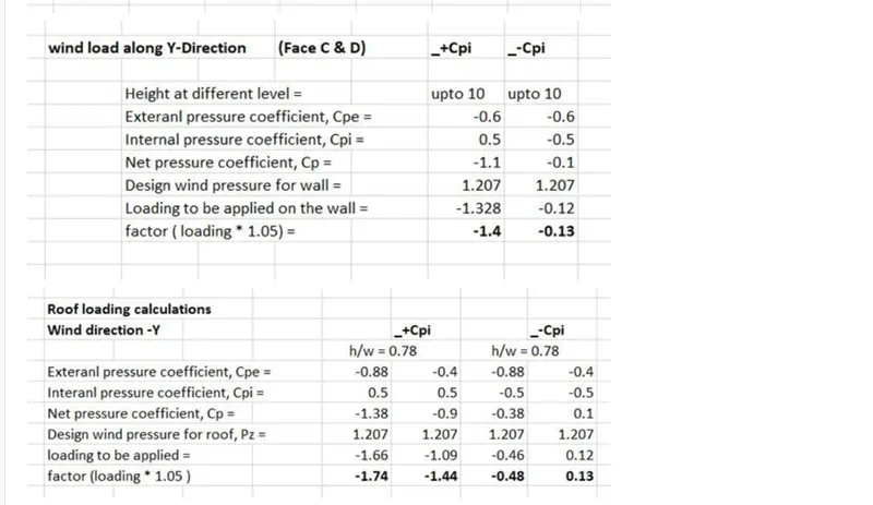
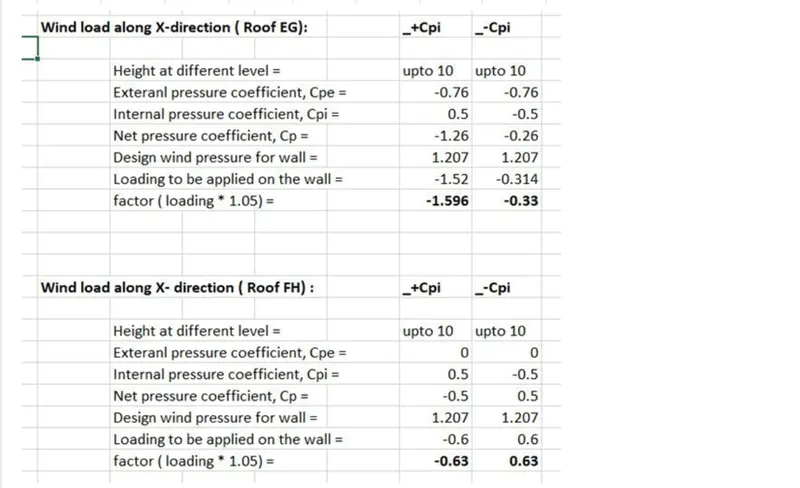
The manual wind loads are calculate in the excel sheet as shown below.
- Next we have define the load cases as shown below.
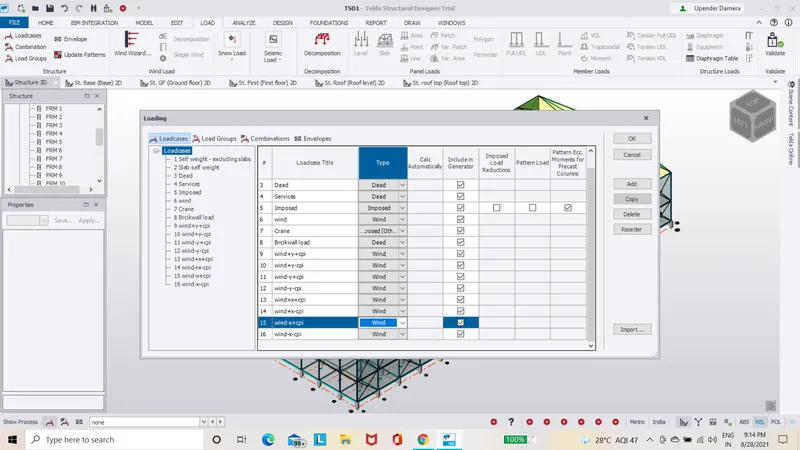
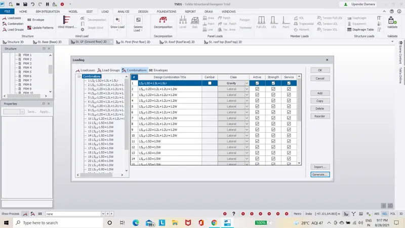
- Next we have to select the different frames and apply the different wind loads to the walls and roofs of the building in different directions as shown below.
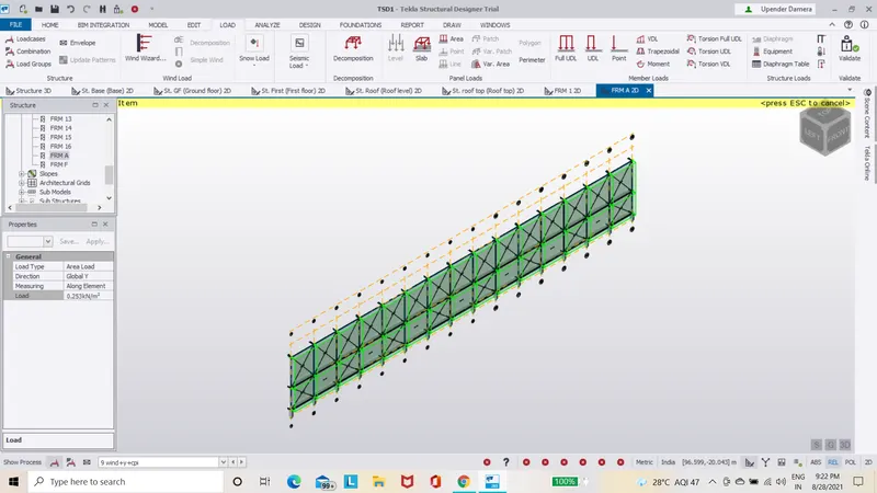
- Selecting the respective frame and applying the respective wind load to the wall panels.
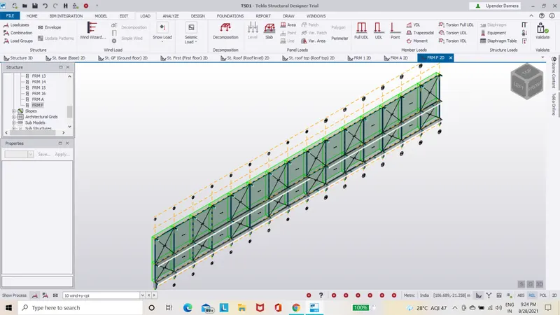
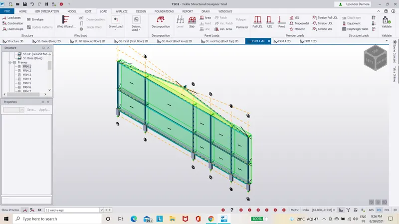
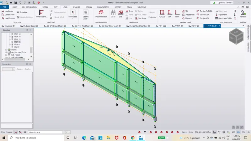
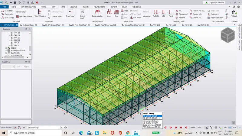
- Next we have to select the validate option and check for errors and if any errors are showed and select the error and resolve the error.

- Now we should perform analysis for the structure,now select settings option from tool bar and check tolerance ,iterations,modifications factors should be 1.
- Now select the 1st order linear option from analysis then one box appears then select load cases and load combinations required for the structure and then click on ok.

- NOw check the analysis result in project status window for any errors.
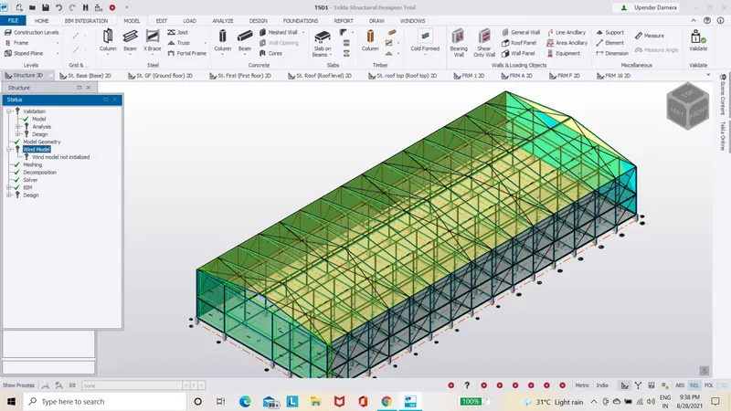
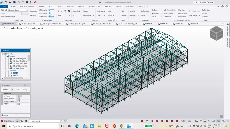
- Now we can see deflection,shear force,torsion options select them individualy and see the results of the structure.
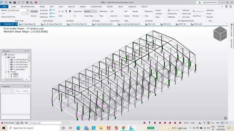
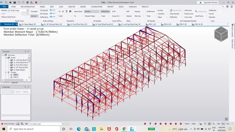
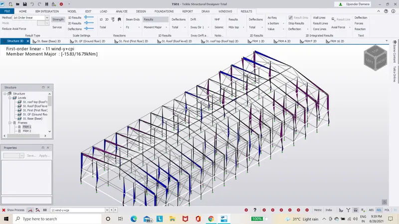
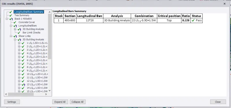
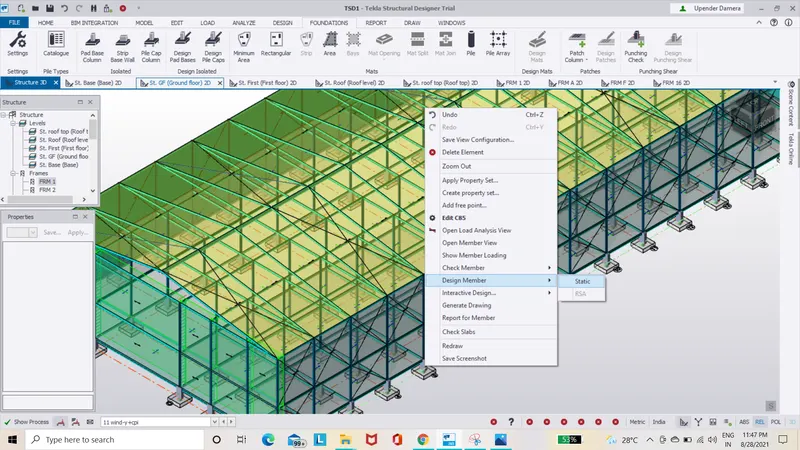
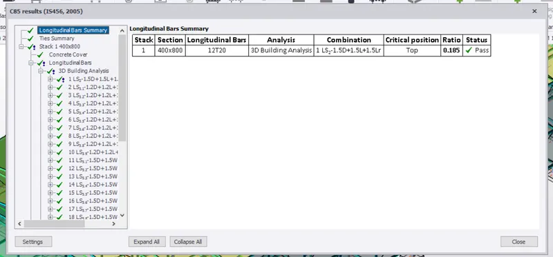
- Then we can check whether every member satisfies load combinations or not.
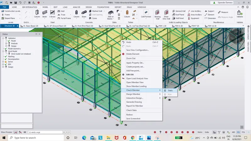
- Check for any errors in load combinations for each member and rectify the errors.
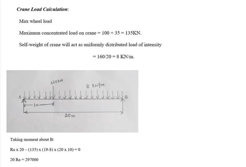
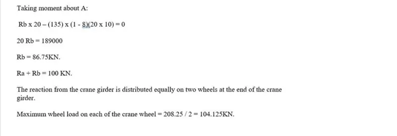
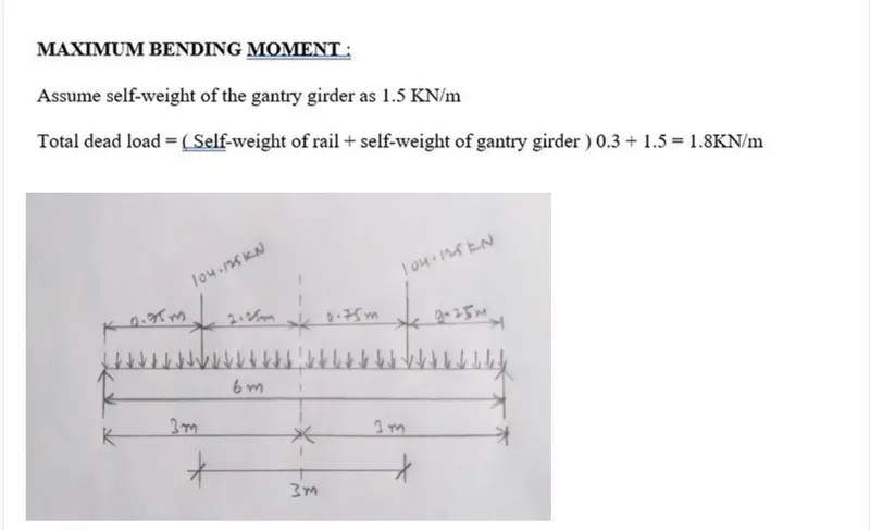
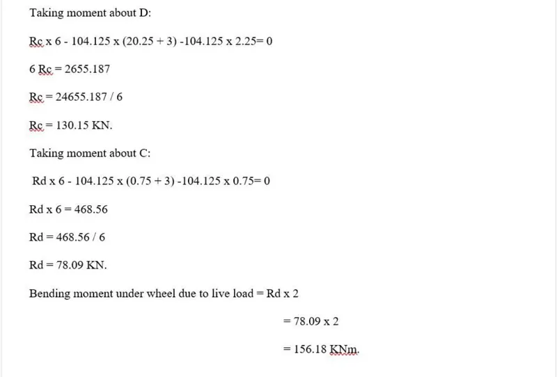
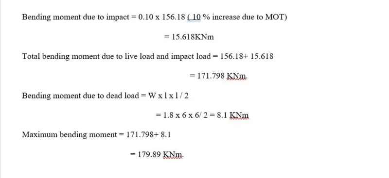
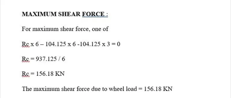
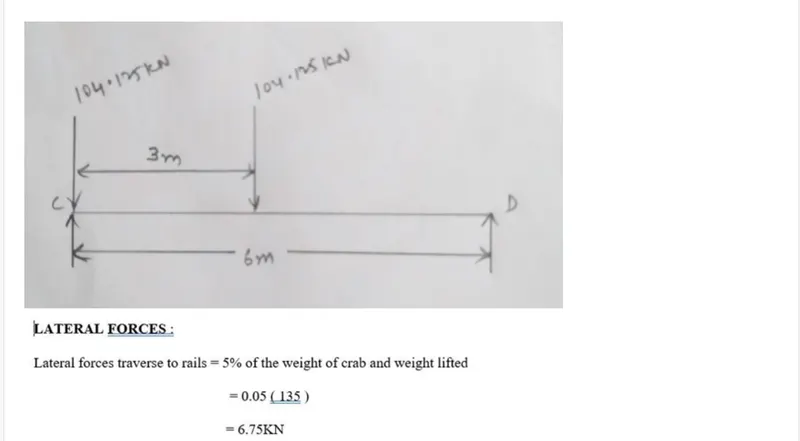
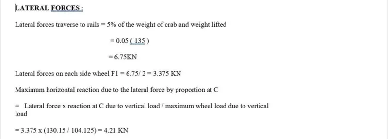
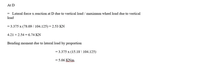
CRANE LOAD CALCULATIONS:-
- Next we have create foundation for columns then now go and select the foundation tool to model foundation for the structure.
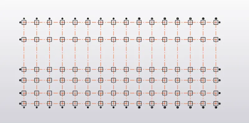
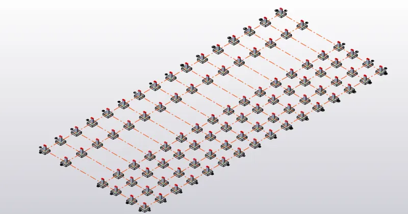
- Now apply same properties for all the foundations using reference node.
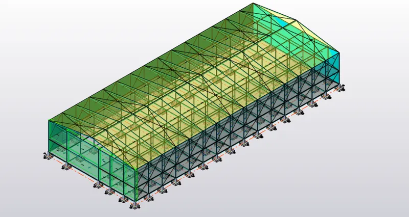
- The final design of the steel structure building with foundation as shown below.
RESULT:-
Therefore by using above procedure analysis and design of a steel Building with 10T CRANE as per IS standard code and to design a structure according to the attachments provided done successfully.